
Draft CD 15
Draft CD 15
Revision as of 17:35, 5 October 2020 by James Klassen (talk | contribs) (Created page with "{| class="wikitable" | style="color: black; background-color: orange; width: 100%;text-align:center" | colspan="2" | <big>'''''Notice to Reader'''''</big> |- | style="color:...")
| Notice to Reader | |
| Images used in a Construction Detail are representative and not intended in their representation of an assembly to be prescriptive. Nor are they necessarily drawn to scale. Rather, they are provided to visually convey the Standards, Guiding Principles and Recommendations of the RoofStar Guarantee Standards for a Waterproofing or Water-shedding System. Actual design with respect to dimensions, the selection of materials and their application remains the responsibility of the Design Authority. The full text of applicable RoofStar Guarantee Standards may be read by using the blue hyperlinks | |
ASM Details
- Click below for a printable version of this page (N/A)

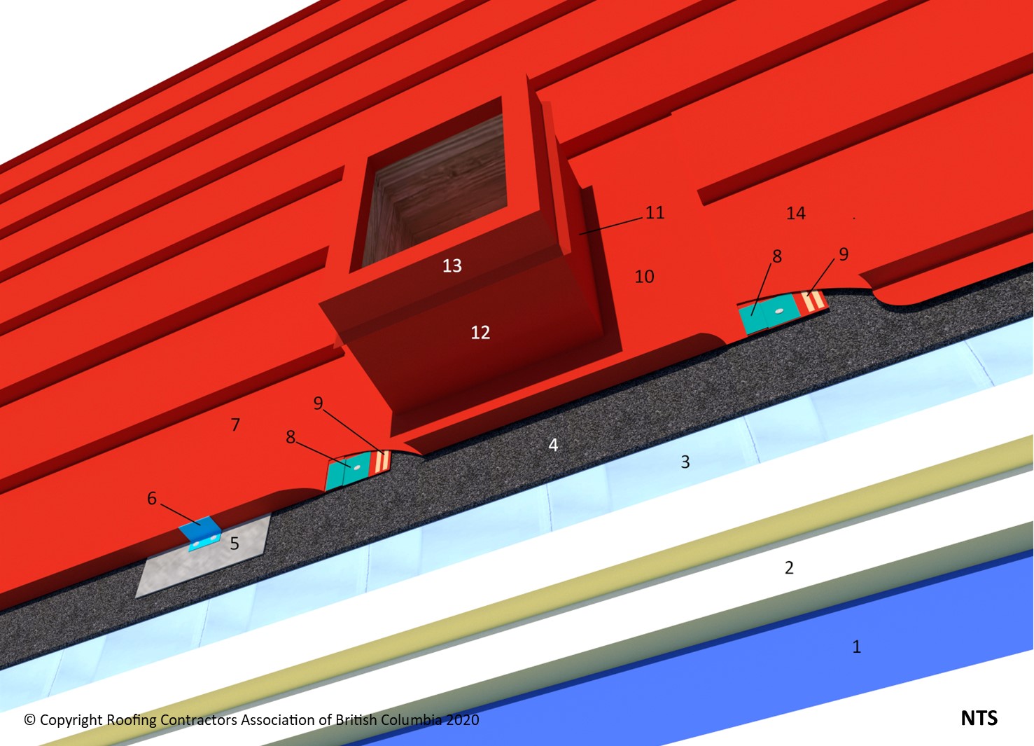
1 WORK INCLUDED
- (1) Underlayment
- The type of underlay required is determined by roof slope.
- (2) Insulation
- Offset and stagger layers 300 mm (12").
- (3) Separation layer
- Vapour-permeable layer over insulation, required on all insulated Architectural Sheet Metal Roof Systems. The material must be located between the insulation and metal panels (see 8.1.2 Design).
- (4) Ventilation layer
- Recommended over asphaltic underlays and / or as required in this Standard (see 8.1.2 Design).
- (5) Bearing plate
- Only thermally non-conductive clips or bars passing through the insulation assembly, or mechanically fastened bearing plates, may be used to secure and support insulation panels, or provide support for panel clips.
- (6) Architectural metal panel clip
- (7) Architectural metal roof panel (lower)
- Lower, installed prior to the pipe flashing, cut hole large enough to allow for movement. Extend 400 mm (16") upslope beyond the pipe.
- (8) Spaced Cleat
- Cleats, set in accepted caulking, spaced 50 mm (2") and fastened with compatible non-corrosive flat head screws.
- (9) Sealant
- (10) Split panel
- (11) Backpan Flashing
- Required for curbs up to 900 mm (36") wide.
- (12) Metal Curb Flashing
- (13) Metal Counter Flashing
- (14) Architectural metal roof panel (upper)
- Installed after penetration flashing. Cut hole for pipe penetration and turn lower panel end under to hook onto cleat.
2 RELATED WORK BY OTHERS
- (A) Acceptable deck
NOTE: Refer to RoofStar Guarantee Standards for additional requirements.
RoofStar Guarantee Standards for Architectural Sheet Metal (ASM) Systems