
Template:Part 10 (Waterproofing Roofs - Single-ply)
Template:Part 10 (Waterproofing Roofs - Single-ply)
1 General
1.1 Definitions
Refer to the Glossary for further definitions of key terms used in this Manual.
- Low door or Low window
- means a rough opening situated lower than a standard door or standard window but no less than 100 mm (4") above the drainage plane.
- Standard door or Standard window
- means a rough opening located at least 200 mm (8”) above the drainage plane.
- Tall parapet
- means a parapet taller than 600 mm (24”).
1.2 Design
1.2.1 RoofStar 15-Year Guarantee
- Refer to 1.3.1 RoofStar 15-Year Guarantee for general requirements, to qualify the project for a RoofStar 15-year Guarantee.
1.2.2 All Projects
- The Design Authority is responsible to specify the connections between the waterproofing or water-shedding system and walls or other building components, particularly where the continuity of air, vapour and water-resistive layers is critical or required by Code. Refer to Part 6 AIR and VAPOUR CONTROLS.
- Mechanical fasteners used to secure a metal flashing or wall finish must be installed at least 89 mm (3 ½”) above the finished waterproofing system.
- Where the roof field adjoins a wall or parapet, the vertical surface must be waterproofed by either of the following options:
- Turn the field membrane up the vertical surface.
- Flash the vertical surface with membrane flashing (see 10.3.2 Membranes).
Regardless of the method, membranes must be carried up a vertical surface at least 200 mm (8”) above the finished waterproofing system. Parapets less than 200 mm (8") in height, low door or low window applications (see Article 10.3.1.8, Low Door and Window Openings) are exempt from this standard. - All membranes installed on parapets, over a low roof edge or on walls must
- be fully adhered to the substrate.
- wrap onto the outside face of the parapet or roof edge and extend downward to overlap any cold joint by at least 50 mm (2”).
- correctly lap any wall membranes or finishes by at least
- 75 mm (3”) when installed underneath wall materials.
- 50 mm (2”) when installed over wall materials.
- Field membranes, or membrane flashing, must extend up a vertical surface at least 200 mm (8”) above the finished waterproofing system, to permit a proper watertight seal. Low parapets, Low door or low window applications (see Article 10.3.1.2.7, Door and Window Openings) are exempt from this standard.
- Membrane and membrane flashing that terminates on a vertical surface must be secured to the substrate by the Contractor, and exposed edges must be protected from water intrusion, physical damage and ultraviolet light exposure. Specify membrane securement and protection using one of the following options, ranked according to the maintenance they require (low to high):
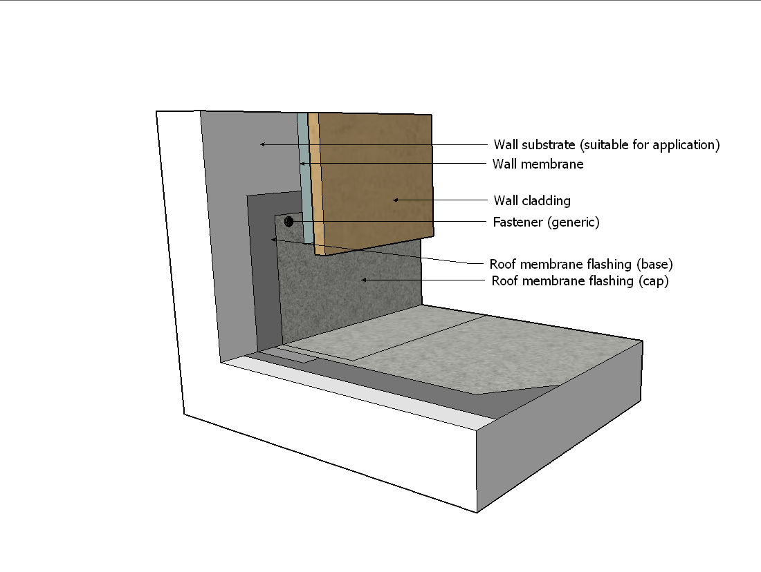
- Adhere the roof membrane to the wall surface, and
- protect the exposed membrane edge with overlapping adhered or self-adhered wall membranes and exterior sheathing (Figure 10.3.1a).
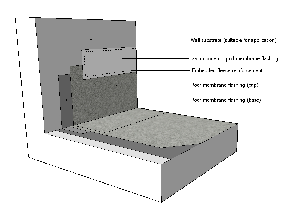
- cover the exposed membrane edge with a secondary, fleece-reinforced 2-component liquid membrane flashing (see 10.3.2.4 Liquid Membrane Flashing for application requirements) (Figure 10.3.1b).
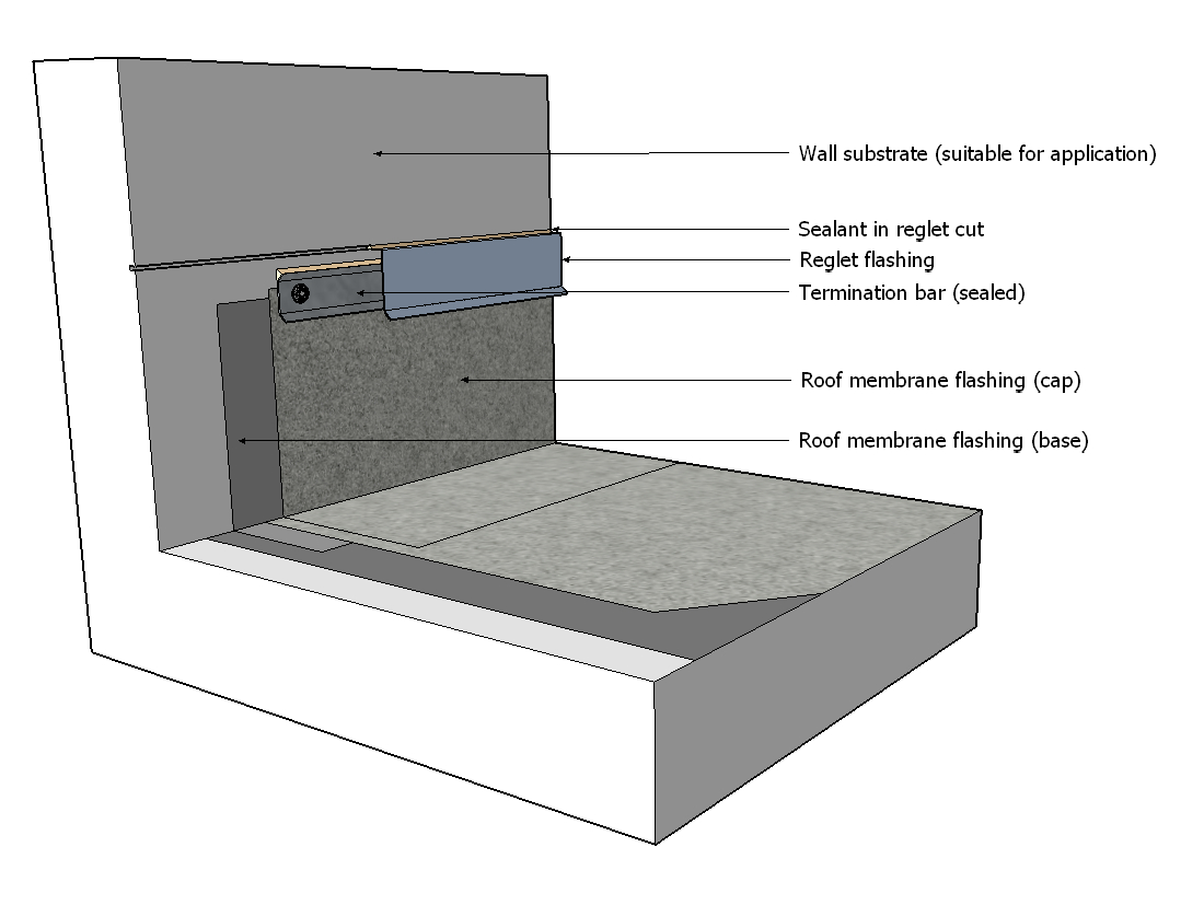
- Mechanically secure the membrane to the wall with a termination bar; caulk the upper edge of the termination bar and cover the bar with a cut reglet flashing sealed inside the reglet cut with an acceptable sealant (see 13.2.4 Sealants) (Figure 10.3.1c).
- Secure the membrane with a surface-mounted reglet flashing:
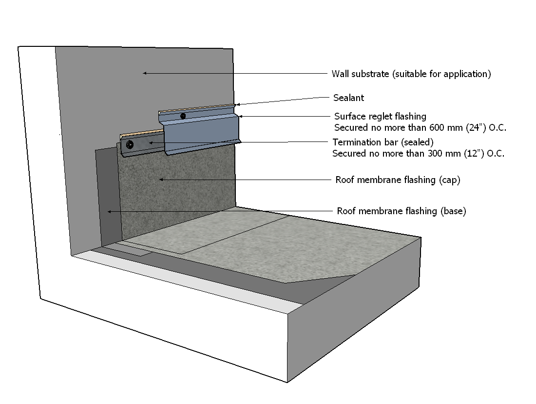
- Mechanically secure the membrane to the wall with a termination bar or metal flashing; caulk the upper edge of the termination bar, and cover the bar with a secondary metal surface reglet flashing that is separately attached to the wall and sealed along the upper edge with an acceptable sealant (see 13.2.4 Sealants) (Figure 10.3.1d).
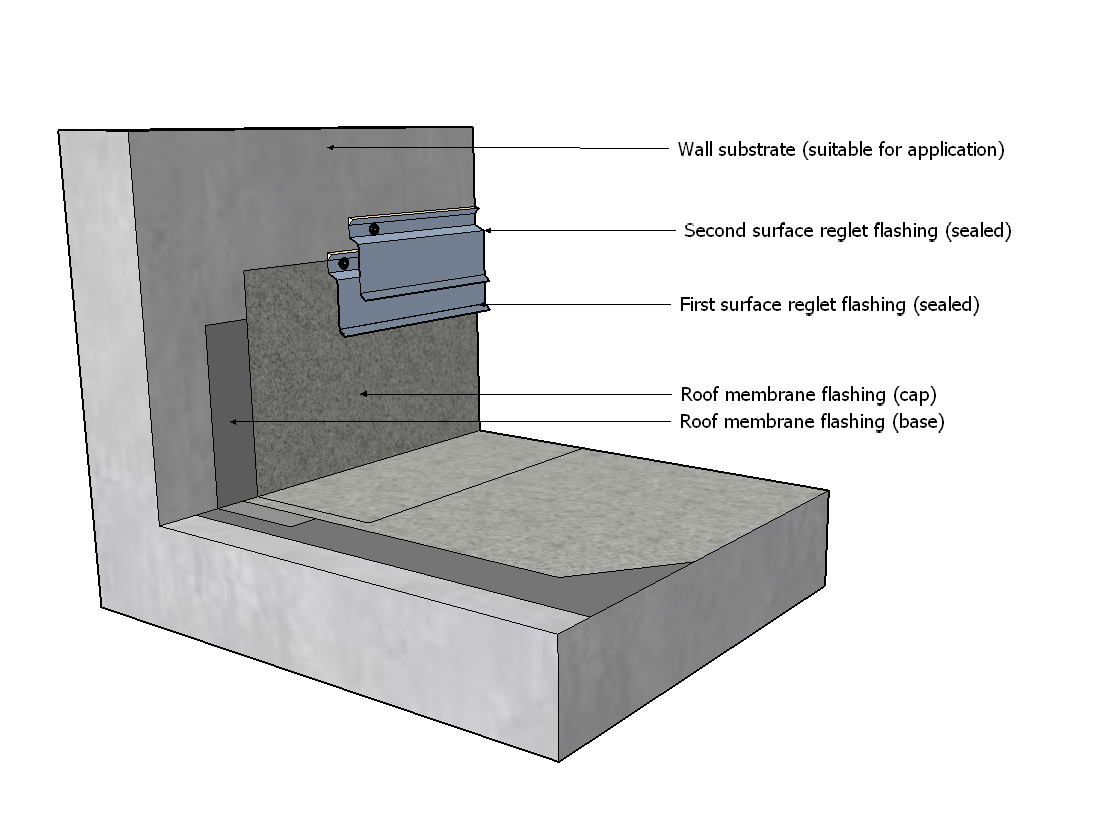
- Mechanically secure the membrane to the wall; surface-mount a reglet flashing above the terminated membrane and seal the metal flashing along the upper edge with an acceptable sealant; install a second surface-mounted reglet flashing and seal it along the upper edge with an acceptable sealant (see 13.2.4 Sealants) (Figure 10.3.1e).
For fastener spacing, see additional Standards in this Part, and 13.3.1 General (Application).
- Adhere the roof membrane to the wall surface, and
- Where a roof allows water to freely drain off the edge, and the roof adjoins a wall, a cricket or diverter should be installed at the roof edge to prevent water intrusion behind wall finishes.
1.2.3 Parapets
In addition to the general requirements in Article 10.1.2.2, the following standards apply:
- Conventionally Insulated Roofs: Parapets are not required for exposed Conventionally Insulated roofs, but when they are specified the parapet must be no less than 125 mm (5") in height, measured from the top of the finished waterproofing system to the inside top edge of the parapet (to facilitate proper metal cap flashing securement). See also 13.3.4 Cap, Counter and Base Flashings.
- Roofs with Overburden or Ballast:
- Parapets (or an alternative retention system that is acceptable to the Guarantor)
- are required at the outside edge of any roof that supports overburden or ballast.
- must be designed to retain overburden or ballast against wind scouring, but the height of the parapet or alternative retention system shall not be less than 200 mm (8”) in height when measured from the top of the finished waterproofing system.
- The minimum parapet height required in 10.1.2.3 (2)(1)(2) may be reduced for a Vegetated Roof System, provided
- the reduced height is supported by a VRS wind test and published report (see 3.1.4.2 Roofs with Ballast and Overburden).
- the Guarantor has issued a written Variance based on the test results and report.
See also Sub-article 14.1.2.2.3 Vegetated Roof Systems for additional securement standards.
- Parapets (or an alternative retention system that is acceptable to the Guarantor)
- All membranes installed on parapets must be fully adhered to the parapet substrate.
1.2.4 Low Roof Edges
In addition to the general requirements in Article 10.1.2.2, the following standards apply:
- When a metal edge termination detail is used, the edge must be fully blocked to support the metal and membrane edges.
- Canted edges
- are not required or recommended, since membranes are manufactured to transition from horizontal to vertical planes without the assistance of an intermediate slope.
- on existing roofs may be left in place, at the discretion of the Design Authority.
1.2.5 Walls
In addition to the general requirements in Article 10.1.2.2, the following standards apply:
- When a roof waterproofing system transitions to a high wall, additional mechanical securement may be required by the membrane manufacturer.
- When a wall or parapet is faced with multi-wythe masonry or composite panels, and the membrane flashing must be installed over the face of the wall or parapet, the through-wall flashing that separates wythes or courses of panels must be
- supplied and installed by others.
- situated at the next course above the terminated edge of the membrane flashing and any metal roof flashings.
Refer to current seismic codes for suitability. In the alternative to the above, the entire inside face of a parapet must be completely flashed or cladded.
1.2.6 Transitions with Water-Shedding Systems
In addition to the general requirements in Article 10.1.2.2, the following standards apply:
- When a roof waterproofing system transitions
- to a water-shedding system, the transition may be flashed with separate membrane plies.
- down a slope onto a lower water-shedding system, the waterproofing system membrane must positively lap the water-shedding system by no less than 50 mm (2").
- up a slope and beneath a water-shedding system,
- the Waterproofing System membrane must extend up the water-shedding slope at least
- 150 mm (6”), or
- 300 mm (12”) in regions with typical heavy snow.
- membranes must be mechanically secured at their upper termination.
- fasteners for the water-shedding system must be at least 89 mm (3 ½”) above the finished surface of the waterproofing system (when measured vertically).
- the water-shedding system materials must overlap the waterproofing system by at least 150 mm (6”).
- the Waterproofing System membrane must extend up the water-shedding slope at least
- with a wall, wall membranes and finishes must positively lap membrane flashing by at least 75 mm (3").
1.2.7 Expansion and Control Joints
In addition to the general requirements in Article 10.1.2.2, the following standards apply:
- Refer to the application standards in Article 10.3.1.7.
1.2.8 Low Door and Window Openings
In addition to the general requirements in Article 10.1.2.2, the following standards apply:
- Standard door and standard window openings must be flashed with membrane, following the requirements in Article 10.3.1.8.
- Rough openings should be oversized to accommodate the build-up of flashing membrane. Existing openings may be flashed using the alternative method described in 10.3.1.8.
- The RGC recommends against low door openings because of their propensity to leak. Nevertheless, when a low door opening is specified to comply with Code, it must be waterproofed in keeping with the requirements in Article 10.3.1.8.
1.2.9 [NOT USED]
2 Materials
2.1 Membranes
- Membranes used to flash (strip) walls, parapets or other edges shall be reinforced with polyester or a composite scrim, but in any event must conform to the membrane requirements found in 9.2.1 Composition, Thickness and Selection.
- Some membranes may be susceptible to damage from bird droppings, pet urine, chemical contamination (oils, solvents or any discharge from a mechanical unit). The Design Authority is strongly urged to consider these issues as part of the overall project design, consult with the membrane manufacturer for guidance, and provide adequate membrane protection when it is necessary. See also 14 THE ROOF as a PLATFORM.
2.2 Fasteners
- Fasteners used to secure the upper termination of membranes must be the fasteners specified by the membrane manufacturer or, when a fastener is not specified, a No. 12 screw-type fastener or impact-driven fastener compatible with all secured materials.
2.3 [NOT USED]
2.4 Metal Flashing
- Linear metal flashings incorporated into roof perimeters and walls must conform to the materials and fabrication standards found in 13.2 Materials.
3 Application
3.1 General
3.1.1 RoofStar 15-Year Guarantee
- Refer to 1.3.1 RoofStar 15-Year Guarantee for general requirements, to qualify the project for a RoofStar 15-year Guarantee.
- EPDM membrane system Projects only: all outside corners must be double-wrapped using semi-cured membrane, installed according to the membrane manufacturer’s published details and written requirements
3.1.2 All Projects
- Projects must follow proper sequencing. This means that materials must be installed so that they interface with other materials, systems, or assemblies, including those installed by other trades, in “shingle fashion” by positively overlapping them below or above. Occasionally, the coordination with other trades requires some adaptation to this Standard. When that is the case, any variance to proper detail sequencing must be approved by the Design Authority in writing.
- All changes in plane must be waterproofed with membrane flashing.
- All installed membranes must be protected from splashed or dripped primer. This standard also applies to work by other trades, who may use primers for self-adhering membranes typically installed on walls or around doors, windows, or other wall penetrations.
- Membranes, or membrane flashing plies, must be installed on vertical surfaces according to the manufacturer's published instructions, but in any event must be
- installed to a substrate that is suitable (see Part 2 SUPPORTING STRUCTURES: Decks and Walls) or is listed under Accepted Materials.
- fully bonded to its substrate.
- installed from the low point of the roof (for positive laps toward the drain).
- installed to extend
- onto the field of the roof, as required by the membrane manufacturer (when separate membrane flashing plies are used).
- at least 200 mm (8”) above the finished waterproofing system, to permit a proper watertight seal. Low parapets, low door or low window applications (see Sub-article 10.3.1.2.7) are exempt from this minimum height requirement.
- installed without fish-mouths or wrinkles.
- hand-rolled with a membrane manufacturer’s accepted roller and fully bonded to an acceptable, prepared substrate.
- reinforced at all inside and outside corners with membrane corner details or seam transition covers
- wherever the membrane flashing changes planes (vertical to horizontal, for example).
- installed in accordance with the manufacturer’s published instructions.
- finished and sealed before the end of the working day.
- correctly lapped with any wall membranes or finishes by at least
- 75 mm (3”) when installed underneath wall materials.
- 50 mm (2”) when installed over wall materials.
- All membranes installed on parapets or over a low roof edge must wrap onto the outside face of the parapet or roof edge and extend downward to overlap any cold joint, including joints between the parapet and the coping, by at least 50 mm (2”).
- Field membrane and membrane flashing that terminates on a vertical surface must be secured to the substrate by the Contractor, and exposed edges must be protected from water intrusion, physical damage and ultraviolet light exposure. This must be accomplished using one of the following options, ranked according to the maintenance they require (low to high):
- Adhere the roof membrane to the wall surface, and
- protect the exposed membrane edge with overlapping adhered or self-adhered wall membranes and exterior sheathing (Figure 10.3.1a).
- cover the exposed membrane edge with a secondary, fleece-reinforced 2-component liquid membrane flashing (see 10.3.8 for application requirements) (Figure 10.3.1b).
- Mechanically secure the membrane to the wall with a termination bar; caulk the upper edge of the termination bar, and cover the bar with a cut reglet flashing sealed inside the reglet cut with an acceptable sealant (see 13.2.4 Sealants) (Figure 10.3.1c).
- Secure the membrane with a surface-mounted reglet flashing:
- Mechanically secure the membrane to the wall with a termination bar or metal flashing; caulk the upper edge of the termination bar, and cover the bar with a secondary metal surface reglet flashing that is separately attached to the wall and sealed along the upper edge with an acceptable sealant (see 13.2.4 Sealants) (Figure 10.3.1d).
- Mechanically secure the membrane to the wall; surface-mount a reglet flashing above the terminated membrane and seal the metal flashing along the upper edge with an acceptable sealant; install a second surface-mounted reglet flashing and seal it along the upper edge with an acceptable sealant (see 13.2.4 Sealants) (Figure 10.3.1e).
For fastener spacing, see additional Standards in this Part, and 13.3.1 General (Application).
- Adhere the roof membrane to the wall surface, and
- When the roof membrane is mechanically secured with a termination bar or a metal flashing,
- fasteners must be spaced no more than 300 mm (12”) O.C.
- and a second metal flashing is installed to protect a termination bar or flashing used to secure the membrane, it may be fastened no more than 600 mm (24”) O.C. provided the metal flashing maintains continuous contact with the substrate. See also 13.3.1 General (Application).
- and closer spacing is required by the membrane manufacturer, the wall must be constructed or modified to facilitate solid fastener securement.
- When a diverter flashing is required, it must be fabricated like a metal edge flashing, and must be secured and sealed to the primary membrane with membrane flashing (stripping). See Article 10.3.1.4.
|
|
|
|
|
3.1.3 Parapets
In addition to the general requirements in Article 10.3.1.2, the following standards apply:
- All parapets:
- All membranes installed on parapets must be
- fully adhered to the parapet substrate.
- terminated on the outside face of the roof edge in keeping with Article 10.3.1.2.
- Where a parapet intersects with a wall, water must be directed to the outer surface of the wall by flashing the union with
- membrane flashing.
- membrane gussets at the corners.
- a metal saddle assembly.
- All membranes installed on parapets must be
- Parapets up to 600 mm (24”) in height:
- Field membrane or membrane flashing must fully cover the parapet, extending onto the outside face.
- Parapets greater than 600 mm (24”) in height (tall parapets):
- Tall parapets should be designed with consideration given to ventilation.
3.1.4 Low Roof Edges
In addition to the general requirements in Article 10.3.1.2, the following standards apply:
- When a metal edge termination detail is used,
- the edge must be fully blocked to support the metal and membrane edges.
- the membranes must be terminated on the outside face of the roof edge in keeping with Article 10.3.1.2.
- Metal edge flashings must be
- installed over the base field membrane.
- embedded in a membrane-compatible mastic.
- fastened to the roof surface with mechanical fasteners spaced 200 mm (8”) O.C. in offsetting rows.
- joined to each other with lap joints measuring at least 100 mm (4”) and sealed with mastic.
- primed.
- sealed to the base membrane which must extend
- at least 100 mm (4") onto the metal flashing, and at least 50 mm (2”) past the fasteners.
- at least 100 mm (4”) onto the field membrane.
- finished with the field cap membrane
- extending to cover the base membrane.
- sealed along the exposed edge with an un-tooled bead of membrane-compatible sealant.
- Existing and new canted edges must be
- made of wood.
- flashed with membrane plies, installed in keeping with the requirements in Article 10.3.1.2, and must lap onto the roof field in keeping with the Standards published in this Part, when measured from the base of the cant.
3.1.5 Walls
In addition to the general requirements in Article 10.3.1.2, the following standards apply:
- When a waterproofing system transitions with a wall, wall membranes and finishes must positively lap the roof system by at least 75 mm (3").
- When walls are specified as part of the roofing work,
- the roof system must be carried up the vertical surface at least 300 mm (12”) to facilitate continuity with wall systems and materials.
- the surface of the wall above the vertical termination of the primary roof membrane must be covered with a water-resistive membrane that has properties consistent with the design and characteristics of the wall assembly. This may be the same membrane used as the primary membrane protection layer, or it may be a self-adhering membrane that is suitable to the primary membrane manufacturer, having a minimum thickness of 1 mm (.040”), provided it
- has a high softening point and a minimum flow temperature of 87.7°C (190°F)(ASTM D5147 high temperature stability).
- is applied with the methodology prescribed by the manufacturer.
- positively overlaps the primary roof membrane and its protection layer by at least 50 mm (2”).
- covers the remainder of the wall or tall parapet.
- is protected from UV radiation with a metal flashing, cladding or another wall covering.
- does not extend to cover the top surface of a parapet.
3.1.6 Transitions with Water-Shedding Systems
In addition to the general requirements in Article 10.3.1.2, the following standards apply:
- Where two roof systems intersect, materials must be compatible with each other, or must be separated from contact by an intermediate separation layer.
- When a waterproofing system transitions
- down a slope onto a lower water-shedding system, the waterproofing membrane must lap over the water-shedding system by no less than 50 mm (2").
- up a slope and beneath a water-shedding system,
- membrane flashing must extend up the water-shedding system slope at least
- 150 mm (6”), plus 75 mm (3”) for the overlap by the water-shedding system, when measured vertically from the maximum water level.
- 200 mm (8”), plus 75 mm (3”) for the overlap by the water-shedding system, when measured vertically from the water plane.
- 300 mm (12”) plus 75 mm (3”) for the overlap by the water-shedding system, when measured vertically from the water plane or maximum water level, in regions with typical heavy snow.
- the termination of the membrane on the slope must be mechanically secured, separately from the water-shedding system.
- fasteners for the water-shedding system must be at least 200 mm (8”) above the finished surface of the waterproofing system (when measured vertically from the water plane), or 300 mm (12”) for regions with heavy snow.
- the water-shedding system materials must overlap the waterproofing system by at least 150 mm (6”).
- membrane flashing must extend up the water-shedding system slope at least
- with a wall, wall membranes and finishes must positively lap membrane flashing by at least 75 mm (3").
3.1.7 Expansion and Control Joints
In addition to the general requirements in Article 10.3.1.2, the following standards apply:
- See 2.4 Expansion Joints and 2.5 Control Joints.
- Expansion joints constructed as a raised divider must have a sloped top surface and must extend in height above the finished waterproofing system no less than 200 mm (8"). The minimum height of the expansion joint may be reduced to 125 mm (5") if the primary roof membrane flashing is fully supported and sealed over the top.
- Proprietary elastomeric expansion joint systems, manufactured with an EPDM-based core and flanges that can be fully bonded to the primary membrane, are acceptable for use in Waterproofing Systems when the systems are located a minimum of 200mm (8") above the finished waterproofing system and are completely sheathed (covered) with sloped linear metal flashing. Such joints must be
- accepted for use in the RoofStar Guarantee Program.
- compatible with the roof membrane and acceptable to the membrane manufacturer.
- designed and manufactured to accommodate building movements of at least 500% elongation at -40°C (-40°F) across its length and at all vulcanized points.
- factory-fabricated by means of vulcanization.
- manufactured as one piece, complete with all joints, details and connections.
- bonded with the primary membrane in a manner acceptable to the manufacturers of both the expansion joint and the membrane to which it will be bonded.
- Field splicing of proprietary elastomeric expansion joints is permitted only when made with a machine acceptable to the expansion joint manufacturer. All other field splices are not permitted.
3.1.8 Low Door and Window Openings
In addition to the general requirements in Article 10.3.1.2, the following standards apply:
- Low door and low window openings are not recommended, but when they are specified or unavoidable, the rough opening at the curb must be waterproofed, before the door frame and sill is installed, by one of the following accepted methods:
- Metal water stop flashing:
- The rough opening must be pre-flashed with the field membrane (or membrane flashing, lapped onto the field membrane)(see 10.3.1.2 (7)), and carried up the sill curb and over the entire top face of the rough opening. Reinforce all corners with appropriate membrane patches or covers.
- A metal water stop flashing must be
- fabricated to fit the full width of the opening and shall incorporate a water dam upstand measuring at least 25 mm (1”) in height.
- embedded in a membrane-compatible sealant, and mechanically attached to the sill.
- sealed to the rough opening with an additional ply of membrane flashing.
- Metal sill pan flashing:
- The rough opening must be pre-flashed with the field membrane (or membrane flashing, lapped onto the field membrane) (see 10.3.1.2 (7)), and carried up the sill curb and over the entire top face of the rough opening. Pre-flashing must also extend vertically on both sides of the opening at least 200 mm (8”).
- A single-piece metal pan sill flashing must be fabricated to fit snugly inside the rough opening; the metal pan flashing shall be
- fabricated with with folded, welded, or soldered corners, and shall incorporate a water dam upstand measuring at least 25 mm (1”) in height.
- made with 100 mm (4”) high flanges that cover the insides of the rough opening and wrap around the outside face of the wall at least 100 mm (4”).
- The metal pan flashing must be
- installed over the pre-flashing base membrane and embedded in a membrane-compatible sealant.
- mechanically attached to both the outside and inside faces of the rough door opening.
- sealed to the rough opening with an additional ply of membrane flashing.
- Reinforced liquid membrane flashing:
- When clearances preclude the use of either of the above options, the rough opening may be flashed using the Metal Water Stop method in combination with a RoofStar-accepted fleece-reinforced 2-component catalyzed polymethyl methacrylate (PMMA) liquid membrane flashing system, or with another RoofStar-accepted liquid flashing system approved for this application. Follow the requirements for liquid membrane flashing systems in Article 10.3.2.4:
- Install upturned field or flashing membrane to the wall, on either side of the rough opening, following the standard requirements in Article 10.3.1.2.
- Pre-flash the rough opening and install the metal water stop flashing as described in the Metal Water Stop method above.
- Seal in the metal water stop flashing to the base membrane pre-flashing using the fleece-reinforced liquid membrane flashing system.
- Waterproof the inside faces of the rough opening with reinforced liquid membrane flashing, ensuring an overlap with the membrane on the sill at least 50 mm (2”). Liquid membrane flashing must extend up the inside faces of the rough opening at least 100 mm (4”).
- When clearances preclude the use of either of the above options, the rough opening may be flashed using the Metal Water Stop method in combination with a RoofStar-accepted fleece-reinforced 2-component catalyzed polymethyl methacrylate (PMMA) liquid membrane flashing system, or with another RoofStar-accepted liquid flashing system approved for this application. Follow the requirements for liquid membrane flashing systems in Article 10.3.2.4:
- Metal water stop flashing:
- The roof must be sloped away from the door or window opening.
- Overflow drains must be
- installed on the same roof area and located at least 25 mm (1") below the rough door or window opening.
- capable of flow rates equivalent to or greater than those of the primary roof drains for the roof areas adjacent to the door opening (see also Article 11.3.2.5, Scuppers and Overflows).
- When the building interior transitions to a patio or occupied roof surface through a flush door opening, the walking surface of the patio or roof must protect the roof membrane from damage and provide a drainage space below the walking surface measuring at least 12.7 mm (1/2”). Alternatively, pea gravel installed on a drainage board may be used.
- Overhangs above the door are recommended wherever practical, to minimize water intrusion that occurs from wind-driven rain or from snow accumulation.
3.2 Membranes
3.2.1 [NOT USED]
3.2.2 Self-adhered
- Self-adhered membranes must be installed on a clean, uncontaminated surface. Dirty or contaminated surfaces must be covered with
- plywood sheathing with a minimum nominal thickness of 9.5 mm (3/8").
- a wall overlay.
3.2.3 Adhesive and Hot-applied
- Adhered membranes must be installed on a clean, uncontaminated surface. Dirty or contaminated surfaces must be covered with
- plywood sheathing with a minimum nominal thickness of 9.5 mm (3/8").
- a wall overlay.
- Hot-asphalt adhered membranes must be installed according to the membrane manufacturers’ installation specifications.