
Difference between revisions of "Template:Part 11 (Waterproofing Roofs - SBS)"
Difference between revisions of "Template:Part 11 (Waterproofing Roofs - SBS)"
| Line 19: | Line 19: | ||
:;''Secondary roof drain'': means an alternate drainage path in the event of large rain events or significant snow melt, typically situated at a higher elevation than a ''primary roof drain''. | :;''Secondary roof drain'': means an alternate drainage path in the event of large rain events or significant snow melt, typically situated at a higher elevation than a ''primary roof drain''. | ||
;: | ;: | ||
| − | + | <div id="DRAIN_DESIGN"></div> | |
===Design (Drainage)=== | ===Design (Drainage)=== | ||
====RoofStar 15-Year Guarantee==== | ====RoofStar 15-Year Guarantee==== | ||
| Line 77: | Line 77: | ||
<li>Roofs that support ''overburden'' or are secured with ballast must be designed to incorporate a ballast guard that surrounds the drain and promotes unrestricted flow. | <li>Roofs that support ''overburden'' or are secured with ballast must be designed to incorporate a ballast guard that surrounds the drain and promotes unrestricted flow. | ||
</li></ol> | </li></ol> | ||
| − | + | <div id="CURB_PENETRATION_DESIGN"></div> | |
===Design (Curbs and Penetrations)=== | ===Design (Curbs and Penetrations)=== | ||
====RoofStar 15-Year Guarantee==== | ====RoofStar 15-Year Guarantee==== | ||
| Line 140: | Line 140: | ||
==Materials== | ==Materials== | ||
| − | |||
===General=== | ===General=== | ||
#{{hilite | Only new drains and penetration flashings listed in this ''Manual'' may be used on a ''project'' designed and constructed to qualify for a '''''RoofStar Guarantee'''''. Reuse of any existing drain (with the exception of serviceable cast iron drains) or any penetration flashing is prohibited and may void the ''Guarantee''. See also '''1.6 RoofStar Guarantee: Coverage and Limitations'''|| 2021-February-5 }}. | #{{hilite | Only new drains and penetration flashings listed in this ''Manual'' may be used on a ''project'' designed and constructed to qualify for a '''''RoofStar Guarantee'''''. Reuse of any existing drain (with the exception of serviceable cast iron drains) or any penetration flashing is prohibited and may void the ''Guarantee''. See also '''1.6 RoofStar Guarantee: Coverage and Limitations'''|| 2021-February-5 }}. | ||
#Membranes used to flash (strip in) drains and penetrations shall be reinforced with polyester or a composite scrim, but in any event must conform to the membrane requirements found in '''9.2.1 Composition, Thickness and Selection'''. | #Membranes used to flash (strip in) drains and penetrations shall be reinforced with polyester or a composite scrim, but in any event must conform to the membrane requirements found in '''9.2.1 Composition, Thickness and Selection'''. | ||
| − | <div id=" | + | <div id="DRAIN_MATERIALS"></div> |
| − | |||
| − | |||
| − | |||
===Roof Drains and Scuppers=== | ===Roof Drains and Scuppers=== | ||
<span class="reference">Roof drains are comprised mainly of two parts: a bowl or flange that is affixed to the roof deck with mechanical fasteners or a proprietary clamping mechanism; and an integral drain stem that connects the bowl or flange to the leader. Roof drains are sized according to the diameter of the drain stem. As stated above under Section 1: Design, the appropriate size and number of roof drains for any given roof area is determined by the relevant building code in force (ref. ''British Columbia Plumbing Code, Division B – Part 2; 2.4.10.4 Hydraulic Loads from Roofs or Paved Surfaces'')</span>. | <span class="reference">Roof drains are comprised mainly of two parts: a bowl or flange that is affixed to the roof deck with mechanical fasteners or a proprietary clamping mechanism; and an integral drain stem that connects the bowl or flange to the leader. Roof drains are sized according to the diameter of the drain stem. As stated above under Section 1: Design, the appropriate size and number of roof drains for any given roof area is determined by the relevant building code in force (ref. ''British Columbia Plumbing Code, Division B – Part 2; 2.4.10.4 Hydraulic Loads from Roofs or Paved Surfaces'')</span>. | ||
| Line 216: | Line 212: | ||
</li></ol> | </li></ol> | ||
</li></ol> | </li></ol> | ||
| − | + | <div id="CURB_PEN_MATERIALS"></div> | |
===Curbs and Penetration Flashings=== | ===Curbs and Penetration Flashings=== | ||
#All membrane-flashed roof flashings for cylindrical penetrations must be manufactured with materials and methods that meet or exceed the requirements set out in ''CSA B272, Prefabricated Self-Sealing Roof Vent Flashings''. Testing by a qualified third party is required to verify compliance with this standard. | #All membrane-flashed roof flashings for cylindrical penetrations must be manufactured with materials and methods that meet or exceed the requirements set out in ''CSA B272, Prefabricated Self-Sealing Roof Vent Flashings''. Testing by a qualified third party is required to verify compliance with this standard. | ||
| Line 251: | Line 247: | ||
<li>Compression sealants must be formulated to provide waterproofed seals under compressive loads. | <li>Compression sealants must be formulated to provide waterproofed seals under compressive loads. | ||
</li></ol> | </li></ol> | ||
| − | + | <div id="GENERAL_APPLICATION"></div> | |
==Application== | ==Application== | ||
===General=== | ===General=== | ||
| Line 288: | Line 284: | ||
##sheet membrane applications are not practicable (i.e. complex geometry). | ##sheet membrane applications are not practicable (i.e. complex geometry). | ||
##the top edge of membrane plies must be terminated on a vertical surface and other means of termination are not practicable or even possible. | ##the top edge of membrane plies must be terminated on a vertical surface and other means of termination are not practicable or even possible. | ||
| − | + | <div id="DRAIN_APPLICATION"></div> | |
===Roof Drains=== | ===Roof Drains=== | ||
====<big>General</big>==== | ====<big>General</big>==== | ||
| Line 297: | Line 293: | ||
#{{hilite | When a roof supports ''overburden'' or is secured with ballast, drains must be installed together with a surrounding ballast guard that promotes water flow. This requirement is in addition to the requirement for a separation space required for ''Vegetated Roof Systems''. See also '''14.1.2.2.3''' ('''6''')|| 2020-July-3 }}. | #{{hilite | When a roof supports ''overburden'' or is secured with ballast, drains must be installed together with a surrounding ballast guard that promotes water flow. This requirement is in addition to the requirement for a separation space required for ''Vegetated Roof Systems''. See also '''14.1.2.2.3''' ('''6''')|| 2020-July-3 }}. | ||
<div id="SBSCASTDRAINS"></div> | <div id="SBSCASTDRAINS"></div> | ||
| − | + | <div id="DRAIN_CAST"></div> | |
====<big>Cast-iron Roof Drains</big>==== | ====<big>Cast-iron Roof Drains</big>==== | ||
<ol> | <ol> | ||
| Line 341: | Line 337: | ||
</li></ol> | </li></ol> | ||
</li></ol> | </li></ol> | ||
| − | + | <div id="DRAIN_INSERT"></div> | |
====<big>Roof Drain Inserts (Replacement Roofing)</big>==== | ====<big>Roof Drain Inserts (Replacement Roofing)</big>==== | ||
<ol> | <ol> | ||
| Line 352: | Line 348: | ||
</li></ol> | </li></ol> | ||
</li></ol> | </li></ol> | ||
| − | <div id= | + | <div id="DRAIN_SPUN"></div> |
| − | |||
====<big>Flange-type Roof Drains</big>==== | ====<big>Flange-type Roof Drains</big>==== | ||
#Flange-type roof drains must be installed after the primary field base membrane has been fully installed. | #Flange-type roof drains must be installed after the primary field base membrane has been fully installed. | ||
| Line 363: | Line 358: | ||
#The membrane patch must be cut to terminate on the flange, and must be aligned with the base field membrane runs, or oriented 45-degrees to the base field membrane. <span class="principles">Continuous visible bleed-out of bitumen along all edges of the patch should be achieved</span>. | #The membrane patch must be cut to terminate on the flange, and must be aligned with the base field membrane runs, or oriented 45-degrees to the base field membrane. <span class="principles">Continuous visible bleed-out of bitumen along all edges of the patch should be achieved</span>. | ||
#The cap membrane must overlap the base membrane patch, and terminate on the flange at the bowl. | #The cap membrane must overlap the base membrane patch, and terminate on the flange at the bowl. | ||
| − | + | <div id="DRAIN_SCUPPER"></div> | |
====<big>Scuppers and Overflows</big>==== | ====<big>Scuppers and Overflows</big>==== | ||
#'''''Open scupper drains''''' may be constructed to match the height of the ''parapet'' or roof edge, and must be fully sealed with the field and perimeter membrane flashing. | #'''''Open scupper drains''''' may be constructed to match the height of the ''parapet'' or roof edge, and must be fully sealed with the field and perimeter membrane flashing. | ||
| Line 377: | Line 372: | ||
##flashed with cap membrane that overlaps the base and terminates on the flange. | ##flashed with cap membrane that overlaps the base and terminates on the flange. | ||
#Clamping collars must be securely installed as designed and where specified. | #Clamping collars must be securely installed as designed and where specified. | ||
| − | <div id=" | + | <div id="CURB_PEN_INSTALLATION"></div> |
| − | |||
| − | |||
| − | |||
| − | |||
===Curbs and Penetration Flashings=== | ===Curbs and Penetration Flashings=== | ||
====<big>General</big>==== | ====<big>General</big>==== | ||
| Line 500: | Line 491: | ||
<li>Pourable sealant pockets should be used only when a purpose-made flashing is not available or practicable. | <li>Pourable sealant pockets should be used only when a purpose-made flashing is not available or practicable. | ||
</ol></li> | </ol></li> | ||
| − | <div id= | + | <div id="CURB_PEN_ALTERANTIVES"></div> |
| − | |||
====<big>Alternative Membrane Flashing Approaches</big>==== | ====<big>Alternative Membrane Flashing Approaches</big>==== | ||
#When field membranes or flashing plies are heat-welded, or if required by construction sequencing, site personnel must assess the best approach. | #When field membranes or flashing plies are heat-welded, or if required by construction sequencing, site personnel must assess the best approach. | ||
| Line 510: | Line 500: | ||
###The base field membrane, which may be torch-applied, must be installed and tied into the pre-flashing (target patch), overlapping the patch by at least 150 mm (6”). | ###The base field membrane, which may be torch-applied, must be installed and tied into the pre-flashing (target patch), overlapping the patch by at least 150 mm (6”). | ||
###The application standards for flashings with flanges must then be followed (see '''11.3.3.1 General'''). | ###The application standards for flashings with flanges must then be followed (see '''11.3.3.1 General'''). | ||
| − | <div id=" | + | <div id="CURB_PEN_LIQUID"></div> |
| − | |||
====<big>Liquid Membrane Flashing</big>==== | ====<big>Liquid Membrane Flashing</big>==== | ||
<ol> | <ol> | ||
| Line 572: | Line 561: | ||
| [[File:Figure 11.3.3.3-1 (SBS).jpg|class=img-responsive | link=http://rpm.rcabc.org/images/1/1c/Figure_11.3.3.3-1_%28SBS%29.jpg | 400 px]] | | [[File:Figure 11.3.3.3-1 (SBS).jpg|class=img-responsive | link=http://rpm.rcabc.org/images/1/1c/Figure_11.3.3.3-1_%28SBS%29.jpg | 400 px]] | ||
|} | |} | ||
| − | <div id= | + | <div id="CURB_PEN_POCKETS"></div> |
| − | |||
====<big>Sealant Pockets</big>==== | ====<big>Sealant Pockets</big>==== | ||
#<span class="recommended">Sealing penetration flashings with sheet membranes or reinforced liquid membrane flashing should be considered impractical before pourable sealant pockets are used</span>. | #<span class="recommended">Sealing penetration flashings with sheet membranes or reinforced liquid membrane flashing should be considered impractical before pourable sealant pockets are used</span>. | ||
Revision as of 16:12, 14 April 2021
1 General
This section pertains to the waterproofing of roof penetrations, curbs, sleepers, drains and any other "details", in order to qualify for a RoofStar Guarantee.
1.1 Definitions
Refer to the Glossary for further definitions of key terms used in this Manual.
- Drain leader
- means "a pipe that is installed to carry storm water from a roof to a storm building drain or sewer or other place of disposal” (British Columbia Plumbing Code, Division A, Part 1).
- Flange-type drain
- means a primary roof drain with a flat, broad flange fabricated from the same material as the bowl and leader, and encompassing the perimeter of the drain bowl or, in the case of flat drains, the drain leader. Flange-style drains are not cast but rather are manufactured from components that are hot-welded. Flange-style drains are typically secured to the roof with mechanical fasteners.
- Overflow drain ("Overflow")
- means a secondary roof drain that serves as a safeguard when roof drains fail. An overflow may be located in the roof field (for example, as a secondary drain) or at the perimeter of the roof.
- Primary roof drain
- means the primary means of draining water from the roof.
- Roof drain
- means “A fitting or device that is installed in the roof to permit storm water to discharge into a leader.” (British Columbia Plumbing Code, Division A, Part 1).
- Scupper drain ("Scupper")
- means an open or closed roof drain that conveys water laterally from one roof area to another, or from the roof directly to the exterior of the building.
- Secondary roof drain
- means an alternate drainage path in the event of large rain events or significant snow melt, typically situated at a higher elevation than a primary roof drain.
1.2 Design (Drainage)
1.2.1 RoofStar 15-Year Guarantee
- Refer to 1.3.1 RoofStar 15-Year Guarantee for general requirements, to qualify the project for a RoofStar 15-year Guarantee.
- All roof areas must be designed with overflow drains that are properly sized and spaced, in keeping with the building and plumbing codes having jurisdiction.
- Only drains and overflows equipped with clamping rings, to secure roofing membranes, qualify for a RoofStar 15-Year RoofStar Guarantee. In the alternative, and when permitted by the membrane manufacturer, a reinforced 2-component liquid membrane flashing may be used to terminate membranes at the drains. Application of this liquid membrane flashing must be in keeping with the Standards in 11.3.3.3 Liquid Membrane Flashing.
1.2.2 All Projects
- With the exception of overflows, scupper drains and membrane gutters, roof drains and penetration flashings for new construction projects must be located at least 300 mm (12”) away from any adjacent drain, penetration, upstand, edge or wall. The separation space is measured between openings, excluding the flange.
- When existing roof drain and penetration locations do not comply with the Standards above, a Variance must be requested from the RoofStar Guarantee Program and accompanied by plan and detail drawings to show how the Guarantee Standards will be met by the design and construction.
- Only cast-iron roof drains, and existing external couplers used to connect drains to leaders, may be re-used for roof replacement projects. All flange-style drains, scuppers and overflows, together with internal drain-to-pipe compression seals, and seals exposed to water or ultraviolet light, must be replaced.
- All penetration flashings must be replaced in a roof replacement project.
- The Design Authority
- is responsible for the design of roof drainage. The size (flow rate) of roof drains and overflows should be determined through the British Columbia Building Code and British Columbia Plumbing Code, with attention given to both average and large rainfall events. For rainfall capacities, refer to the British Columbia Building Code, Div. B, Appendix C, Table C-2 which lists rainfall loads using specific reference locations throughout the province.
- should coordinate the various disciplines (including, without limitation, mechanical (plumbing) and structural engineers) to calculate proper flow
rates, head pressure and structural supports, in anticipation of significant, short-duration rain events. Consideration should be given to the following design elements (listed without limitation):
- Roof slope – more slope theoretically increases drainage and lessens live loading from rainfall (see also 2.2 Roof Slope).
- Rainfall rates for primary and overflow drainage.
- Primary and overflow drain capacities.
- Hydraulic head (pressure).
- Location of drainage plane (relative to the top of the finished waterproofing system) – the location of the drainage plane may affect the determination of live loads, which should be accounted for as part of drainage design.
- Location of overflows.
- Roof drains must not be used as a conduit for other services, such as electrical. All other services must be designed to utilize separate penetration points with purpose-made penetration flashings and Guarantee-compliant detailing.
- Roofs may drain off a roof edge or by means of internal plumbing. Both are permissible under the RoofStar Guarantee Program.
- When a roof is designed to drain off an edge, water may drain freely or be collected by means of an external or built-in gutter (12.2 Built-in Membrane Gutters) and drained onto a lower roof assembly. The membrane on the lower roof must be protected from abrasion with splash pads.
- When roofs are designed to drain through internal plumbing, the following standards, guiding principles and recommendations apply.
- Drain sumps should be incorporated into a roof design whenever possible, to increase head pressure above primary roof drains. Drain sumps should be designed at least 1m x 1m (39” x 39”) in size. The depth of a sump is a function of insulation thickness (see 7.1.2.10). Sumps designed with sloped insulation are strongly recommended.
- Drain sump durability may be enhanced by specifying additional reinforcement around the perimeter, using a reinforced 2-component liquid membrane flashing system.
- New and existing buildings should incorporate overflows to handle large rain events. The primary function of an overflow is to keep a roof from collapsing when primary roof drains are plugged or cannot drain heavy rainfall. Where no overflows are specified, the building structure should be designed to carry the total load of water collected on the roof, in the event of primary roof drain failure (refer to the British Columbia Building Code).
- When overflows are specified, they must be
- located
- no higher than 100 mm (4”) above the drainage plane.
- so that they freely and visibly discharge storm water.
- protected with a ballast guard when the overflow is located below the top (“finished”) surface of a Protected Membrane Roof System.
- designed with an opening sufficient in size to equal or exceed the rate of rainfall.
- designed as open-wall scuppers for parapets measuring 150 mm (6”) or less in height.
- designed around the principles of a through-wall scupper, for parapets higher than 150 mm (6”).
- located
- Overflows must incorporate a continuous flange surrounding the drain opening, measuring at least 100 mm (4”) in width, and may be manufactured from ferrous metals, subject to the material standards for metal found in this Manual.
- Overflows are required to prevent water intrusion through low door or low window details. In these applications, the overflow must be installed at least 1” lower than the lowest elevation of the door or window opening.
- A scupper drain may serve either as a primary roof drain or as a secondary drain.
- All drains located at the water plane must be fully blocked above the supporting deck structure.
- If a flow restrictor is present in an existing cast drain leader, the restrictor should be reinstalled.
- Drain extensions for cast-iron roof drains should be avoided, since the connection with the cast drain is not sealed; the result is a leak into the roof system.
- Roofs that support overburden or are secured with ballast must be designed to incorporate a ballast guard that surrounds the drain and promotes unrestricted flow.
1.3 Design (Curbs and Penetrations)
1.3.1 RoofStar 15-Year Guarantee
- Refer to 1.3.1 RoofStar 15-Year Guarantee for general requirements, to qualify the Project for a RoofStar 15-year Guarantee.
- When a roof is replaced, all penetration flashings that do not utilize a fitted cap must be installed with clamped double storm collars that are fully sealed around the upper edge. For roofs on newly constructed buildings, the Contractor is responsible to supply and install a second storm collar around the penetration (the first collar is typically supplied and installed by others).
- All electrical, gas and other services that penetrate the roof system must be protected against water intrusion with
- proprietary flashings that are sealed into the roof system.
- curbs fitted with a “weather head” hood sealed into the curb membrane flashing.
- sealant pockets (used only where unavoidable) that comply with the RoofStar 15-year Guarantee Standards found in 11.3 Application.
- Penetrations in Conventionally Insulated Systems must use either of the following:
- Non-ferrous flashings.
- Galvanized, hot-welded flashings and vents (in keeping with the requirements in 11.3.3.1 (10)), provided the flashings, when used at the water plane, are
- elevated on curbs, or
- coated with a reinforced catalyzed two-component liquid membrane, or
- coated with two cured applications of an accepted coating.
1.3.2 All Projects
- With the exception of overflows, scupper drains, and membrane gutters, roof drains and penetration flashings for new construction Projects must be located at least 300 mm (12”) away from any adjacent drain, penetration, upstand, edge or wall. The separation space is measured between openings, excluding the flange.
- When existing roof drain and penetration locations do not comply with the Standards above, a Variance must be requested from the RoofStar Guarantee Program and accompanied by plan and detail drawings to show how the Guarantee Standards will be met by the design and construction.
- All penetration flashings must be replaced in a roof replacement project.
- Roof openings must be enclosed and sealed
- with curbs.
- penetration flashings.
- Except where fully enveloped sleepers are incorporated in the design, all membrane flashing (stripping) must extend vertically on perimeter surfaces at least 200 mm (8") above the roof field membrane, to permit a proper watertight seal. Where pavers, ballast, growing media or any other types of overburden are designed for placement on top of the field membrane, both membrane flashing and purpose-made penetration flashings must be carried vertically past the finished waterproofing system at least 200 mm (8”). see 11.1.2.1 Drainage; see also 11.3.2.5 Scuppers and Overflows).
- Curbs must be designed so that they can be secured directly to the deck structure, or to intermediate blocking. Curbs must not be situated on top of the roof system.
- Galvanized flashings and vents
- are permitted on Uninsulated Systems or Conventionally Insulated Systems, provided
- the base is coated (see 11.3.3.1 (12)).
- the penetration opening does not exceed 0.126 m2 (196 in.2).
- are not permitted at the water plane in a Protected Membrane Roof System or Modified Protected Membrane Roof System. Instead, the penetration must be enclosed by a curb measuring at least 200 mm (8") in height above the finished waterproofing system; the galvanized or welded flashing may then be installed and flashed in on top of the curb.
- larger than 0.126 m2 (196 in.2) must be enclosed or supported by a curb.
- are permitted on Uninsulated Systems or Conventionally Insulated Systems, provided
- Aluminum or copper flashings for penetrations may be located at the water plane in any assembly type.
- Reinforced liquid membrane flashing systems may be specified only where
- sheet membrane applications are not practicable (i.e. complex geometry).
- the top edge of membrane plies must be terminated on a vertical surface and other means of termination are not practicable or even possible.
- Roof penetration flashings must be
- suitable for only one penetration.
- properly fitted to form a seal around the penetration.
- Where a standard flashing is not tall enough to enclose and seal the penetration, the joint between the penetration and the flashing must be sealed with alternative methods.
- Single or multiple penetrations may not be flashed with an open-topped flashing filled with sealant, but must be sealed into the roof system with one of the following options:
- Electrical cable penetrations must utilize a gooseneck-type flashing with a weather hood.
- Pipe-type penetrations must be sealed with
- the manufacturer’s proprietary rubber-based friction seals, mechanical clamps or gooseneck type design.
- a 2-part site-fabricated or proprietary flashing with a removable inspection/access cap (see Construction Detail SBS 11.3.3.3-2).
- Roof curbs and customized metal hoods.
- Sleepers or equipment pads that are completely sealed (enveloped) must be at least 100 mm (4") in height above the finished waterproofing system, but when they are capped with a metal flashing they must be at least 125 mm (5") in height. All penetrations through the top surface of a sleeper or equipment pad must be additionally sealed using
- a compression sealant between the membrane and equipment supports.
- a universal sealant applied around the edges of equipment supports.
- Housekeeping pads situated on top of the finished roof surface and supporting a combined load less than 90 kg (200 lbs) must be separated from the roof with a bond-breaking layer (i.e. XPS insulation). Housekeeping pads supporting larger loads must conform to the standards for sleepers or equipment pads.
- When mechanical equipment that is ventilated on the roof extracts and discharges grease, chemicals or other contaminants that may adversely impact the roof membrane or other system components, the Design Authority should specify additional protection measures (for example, grease guards or a reinforced 2-part liquid membrane coating).
- Guardrails should be designed for attachment on vertical surfaces only; attachment of guardrails to a horizontal surface is strongly discouraged.
- Pourable sealant pockets should be used only as a last resort when other flashing methods are impractical. See also 11.3.3.4 Sealant Pockets for Application requirements.
2 Materials
2.1 General
- Only new drains and penetration flashings listed in this Manual may be used on a project designed and constructed to qualify for a RoofStar Guarantee. Reuse of any existing drain (with the exception of serviceable cast iron drains) or any penetration flashing is prohibited and may void the Guarantee. See also 1.6 RoofStar Guarantee: Coverage and Limitations.
- Membranes used to flash (strip in) drains and penetrations shall be reinforced with polyester or a composite scrim, but in any event must conform to the membrane requirements found in 9.2.1 Composition, Thickness and Selection.
2.2 Roof Drains and Scuppers
Roof drains are comprised mainly of two parts: a bowl or flange that is affixed to the roof deck with mechanical fasteners or a proprietary clamping mechanism; and an integral drain stem that connects the bowl or flange to the leader. Roof drains are sized according to the diameter of the drain stem. As stated above under Section 1: Design, the appropriate size and number of roof drains for any given roof area is determined by the relevant building code in force (ref. British Columbia Plumbing Code, Division B – Part 2; 2.4.10.4 Hydraulic Loads from Roofs or Paved Surfaces).
Roof drains can be further classified as internal or external. Internal roof drains are connected to leaders located and connected to a storm building drain or sewer inside the exterior surface of a building. Internal roof drains may be made of cast iron (secured to the roof assembly with clamps) or from copper or aluminum, fashioned from spun components that are welded together and incorporate a flange around the drain bowl.
External roof drains direct storm water outside the exterior surface of a building. Scuppers and overflow drains are the common types of external roof drains, and may connect to leaders or simply drain freely. Any requirements for leaders and connections to leaders may be found in the applicable municipal and provincial building and plumbing codes (ref. British Columbia Building Code, Division B, 5.6.2.2 Accumulation and Disposal).
- All flange-style drains must be manufactured with a hot-welded or seamless flange at least 100 mm (4”) wide when measured from the outer edge of the drain opening.
- Cast-iron Roof Drains must be
- supplied with a sump receiver and under-deck clamp.
- installed by the trade supplying the roof drain.
- Lead flashings, when specified, must be sized to extend past the drain bowl by at least 150 mm (6”), and must have a weight of at least 15 kg/m2 (3 lb/ft2).
- Internal flange-type roof drains must be
- hot-welded at the joints between the bowl/flange and drain stem.
- constructed of non-ferrous material:
- Copper drains for internal application shall be formed from a minimum weight of 24 oz. sheet copper (20-gauge; 0.812 mm or 0.032”).
- Aluminum drains for internal application shall be formed from a minimum of 12-gauge material (0.820 mm or 0.0325”).
- External flange-type roof drains must be
- hot-welded at the joints between the bowl/flange and drain stem.
- constructed of non-ferrous material:
- Copper drains for external application shall be formed from a minimum weight of 16 oz. (24-gauge; 0.55 mm or 0.0216”).
- Aluminum drains for external application shall be formed from a minimum of 20-gauge material (0.812 mm or 0.032”).
- Only mechanical compression type seals may be used to connect insert-type drains to internal drain leaders.
- Scupper drains (open or closed) must be
- manufactured with welded seams and joints.
- fabricated from
- copper with a minimum weight of 16 oz. (24-gauge; 0.55 mm or 0.0216”).
- aluminum with a minimum thickness of 20-gauge (0.812 mm or 0.032”).
- fabricated with a continuous flange surrounding the drain opening, measuring at least 100 mm (4”) in width.
- designed to extend past the outside face of the wall.
- Closed (boxed) scupper drains must be
- fabricated from
- copper with a minimum weight of 16 oz. (0.55 mm or 0.0216”).
- aluminum with a minimum thickness of 20-gauge (0.812 mm or 0.032”).
- fully enclosed on four sides, for through-wall applications.
- fitted with an overflow opening at the outside face
- equal in capacity to the main drain leader opening.
- at least 38 mm (1 ½”) lower than the top surface of the scupper drain.
- fabricated with a drip edge at the bottom outside edge of the drain to deflect overflow water away from the building.
- fabricated from
- Overflow drains' must incorporate a continuous flange surrounding the drain opening, measuring at least 100 mm (4”) in width, and may be manufactured from ferrous metals, subject to the material standards for metal found in this Manual. Pipe-styled overflow drains must be welded at the flange.
- All roof drains utilized in a roof assembly that includes gravel ballast or growing media (soil) must be supplied with the drain manufacturer's proprietary primary drain strainer and secondary stainless-steel ballast guard. In the absence of a proprietary ballast guard, a custom-fabricated guard may be used provided it meets the following requirements:
- Fabricated from 20-gauge stainless-steel.
- Incorporates 6 mm (1/4”) perforations.
- Equal to or greater in height than the top of the finished waterproofing system.
2.3 Curbs and Penetration Flashings
- All membrane-flashed roof flashings for cylindrical penetrations must be manufactured with materials and methods that meet or exceed the requirements set out in CSA B272, Prefabricated Self-Sealing Roof Vent Flashings. Testing by a qualified third party is required to verify compliance with this standard.
- Notwithstanding the above, all penetration flashings must be
- watertight and seamless or, in the alternative, fabricated with fully hot-welded joints.
- at least 8" in height, from the flange to the opening or top of the flashing.
- fabricated with a hot-welded or seamless flange at least 100 mm (4") wide, around the bottom of the flashing.
- fabricated with a tightly-fitted or mechanically attached settlement cap or lid (if so required).
- All plumbing vent flashings shall be non-ferrous.
- Galvanized flashings and vents must
- meet or exceed the CSA A93 Standard.
- be made with material no less than 26-gauge galvanized steel conforming to the metal standards found in Part 13 METAL FLASHINGS of this Standard.
- Single or multiple penetrations may not be flashed with an open-topped flashing filled with sealant, but must be sealed into the roof assembly with one of the following options:
- Electrical cable penetrations must utilize a gooseneck-type flashing with a weather hood.
- Pipe-type penetrations must be sealed with
- the manufacturer’s proprietary rubber based friction seals, mechanical clamps or gooseneck type design.
- A 2-part site-fabricated or proprietary flashing with a removable inspection/access cap (see Construction Detail SBS 11.3.3.3-2 Penetration Flashings (two-part cable)).
- Roof curbs and customized metal hoods.
- 2-component fleece-reinforced liquid membrane flashing as described in 11.3.3.3 Liquid Membrane Flashing.
- Penetration flashings should be selected for their ability to inhibit the intrusion of vermin and insects into the roof assembly and building interior.
2.4 Fasteners
- Mechanical fasteners used to secure the roof membrane and penetration flashings or related accessories must be
- properly sized in accordance with roof system securement requirements (see 3 SECURING the ROOF ASSEMBLY).
- self-drilling purpose-made screws having a deep-recessed head.
2.5 Sealants
- Sealants must be manufactured by or acceptable to the membrane manufacturer.
- Compression sealants must be formulated to provide waterproofed seals under compressive loads.
3 Application
3.1 General
3.1.1 RoofStar 15-Year Guarantee
- Refer to 11.1.2.1 and 11.1.3.1 for requirements to qualify for a RoofStar 15-Year Guarantee.
- When a roof is replaced, all penetration flashings that do not utilize a fitted cap must be installed with clamped double storm collars that are fully sealed around the upper edge. For roofs on newly constructed buildings, the Contractor is responsible to supply and install a second storm collar around the penetration (the first collar is typically supplied and installed by others).
- All electrical, gas and other services that penetrate the roof assembly must be protected against water intrusion with
- proprietary flashings that are sealed into the roof system.
- curbs fitted with a “weather head” hood sealed into the curb membrane flashing.
- sealant pockets (used only where unavoidable) that
- comply with the requirements in 11.3.3.4 Sealant Pockets, and
- are at least 100 mm (4”) tall, or elevated the same distance above the water plane, when measured from the water plane to the top of the pocket.
- Penetrations in Conventionally Insulated Systems must be flashed using either of the following Accepted materials:
- Non-ferrous flashings.
- Galvanized, hot-welded flashings and vents (in keeping with the requirements in 11.3.3.1 (12)), provided the flashings, when used at the water plane, are
- elevated on curbs, or
- coated with a reinforced catalyzed two-component liquid membrane, or with two cured applications of an accepted coating. In either case, the coating must cover the flashing surface at the membrane seal.
3.1.2 All Projects
Several of the following standards may also be found in 11.1.2 Design:
- With the exception of overflows, scupper drains and membrane gutters, roof drains and penetration flashings for new construction projects must be located at least 300 mm (12”) away from any adjacent drain, penetration, upstand, edge or wall. The separation space is measured between openings, excluding the flange.
- When installing heat-welded membranes, or where construction sequencing requires it, alternatives to conventional membrane flashing should be considered. Refer to 11.3.3.2 Alternative Membrane Flashing Approaches.
- All membrane flashing must be hand rolled with a membrane manufacturer’s accepted roller.
- All inside and outside corners of membrane-flashed penetrations and drainage sumps must be reinforced with membrane gussets, measuring at least 100 mm x 150 mm (4” x 6”), excluding the tapered ends.
- Reinforced liquid membrane flashing systems may be specified only where
- sheet membrane applications are not practicable (i.e. complex geometry).
- the top edge of membrane plies must be terminated on a vertical surface and other means of termination are not practicable or even possible.
3.2 Roof Drains
3.2.1 General
- Roof drains and cap membrane seams must be offset from each other at least 300 mm (12”), measured from the edge of the drain.
- All insert-type drains shall be connected to internal leaders using only mechanical compression type seals. “O”- rings, mastics and caulking are not acceptable methods for sealing these types of drains to leaders.
- All clamping rings and strainers must be unbroken, properly seated and fully secured.
- When a 2-part liquid membrane flashing is specified for reinforcement of drain sumps, the liquid membrane flashing must continuously cover the sides of the sump, overlapping both the sump bottom and the roof field by at least 100 mm (4”).
- When a roof supports overburden or is secured with ballast, drains must be installed together with a surrounding ballast guard that promotes water flow. This requirement is in addition to the requirement for a separation space required for Vegetated Roof Systems. See also 14.1.2.2.3 (6).
3.2.2 Cast-iron Roof Drains
- When cast-iron roof drains are used, a sump receiver and under-deck clamp must be provided and installed by the trade supplying the roof drain.
- Drain extensions for cast-iron roof drains should be avoided.
- Notwithstanding the above, if a flow restrictor is present in an existing cast drain leader, the restrictor should be reinstalled.
- All cast-iron roof drains must be
- flashed in accordance with the membrane manufacturer's published instructions, or to the standards published in this Part, whichever are greater.
- new or clean, and the drain and clamping rings must be unbroken.
- Cast-iron drains installed with lead flashing:
- The continuity of air and vapour control layers must be maintained, where the controls are specified.
- All roof system components, including tapered insulation, must be cut to fit closely around the drain bowl and leader.
- The drain flange must be clean and dry.
- The base field membrane must
- neatly fit around the outside edge of the cast drain flange.
- be prepared to receive a coat of mastic. Follow the membrane manufacturer’s published instructions.
- A membrane-compatible mastic must be applied to the field membrane, and to the drain flange.
- The lead flashing must be centred over the drain body.
- The lead flashing must extend inside drain bowl at least 25 mm (1"). Ensure the lead is moulded to conform to the contours of the drain bowl.
- A reinforcement membrane patch of modified bituminous base sheet material 3 mm or more in thickness must be applied over the lead flashing and onto the field base membrane, ensuring a full bond between the two. The patch must be at least 1m x 1m (39” x 39”) and extend at least 150 mm (6”) past the outside edge of the lead flashing. Continuous visible bleed-out of bitumen around all edges of the patch should be achieved.
- The cap field membrane must be installed according to the General standards for field membranes (See 9.1 General). The membrane must extend past the inside edge of the drain bowl.
- The clamping ring must be seated and secured, ensuring it is not broken.
- The drain screen must be securely installed.
- Cast-iron drains installed with membrane flashing:
- The continuity of air and vapour control layers must be maintained, where the controls are specified.
- All roof system components, including tapered insulation, must be cut to fit closely around the drain bowl and leader.
- The drain flange must be clean and dry.
- The base field membrane must be prepared to receive a reinforcement membrane patch. Follow the membrane manufacturer’s published instructions.
- The drain flange must be primed with the membrane manufacturer’s accepted primer.
- A reinforcement membrane patch of modified bituminous base sheet material 3 mm or more in thickness must be applied over the drain flange and onto the roof field. The patch must be at least 1m x 1m (39” x 39”) and extend at least 150 mm (6”) past the outside edge of the drain body. Continuous visible bleed-out of bitumen around all edges of the patch should be achieved.
- The membrane patch must be trimmed to the inside edge of the drain bowl.
- The cap field membrane must be installed according to the General standards for field membranes (See 9.1 General). The membrane must extend past the inside edge of the drain bowl.
- The clamping ring must be seated and secured, ensuring it is not broken.
- The drain screen must be securely installed.
3.2.3 Roof Drain Inserts (Replacement Roofing)
- An external coupling is preferable to an internal mechanical compression seal, but when an internal compression seal is used out of necessity, the joint must be properly prepared to ensure the joined surfaces are clean, smooth and uniform. Honing out the cast pipe may be required.
- When a cast-iron roof drain has deteriorated to the extent that it cannot receive a new roof membrane, installation must conform to the membrane manufacturer's published instructions, or to the following requirements, whichever are greater:
- Remove any broken parts and debris.
- Install the drain insert utilizing a compression seal (see 11.3.2.1 General).
- Follow the requirements set out in 13.3.2.4 Flange-type Roof Drains.
3.2.4 Flange-type Roof Drains
- Flange-type roof drains must be installed after the primary field base membrane has been fully installed.
- The drain flange must be
- embedded in a continuous trowelled bed of mastic, applied to a prepared compatible base membrane.
- secured to the supporting deck structure or intermediate blocking. Mechanical fasteners used for this purpose must be self-drilling purpose-made screws having a deep-recessed head.
- Drain flanges must be pre-primed before installation of the reinforcement membrane patch.
- All flange-type drains must be sealed to the field base membrane with a reinforcement membrane patch 3 mm or more in thickness, cut large enough to extend past the drain flange by at least 150 mm (6”), and sealed onto the flange and the field base membrane.
- The membrane patch must be cut to terminate on the flange, and must be aligned with the base field membrane runs, or oriented 45-degrees to the base field membrane. Continuous visible bleed-out of bitumen along all edges of the patch should be achieved.
- The cap membrane must overlap the base membrane patch, and terminate on the flange at the bowl.
3.2.5 Scuppers and Overflows
- Open scupper drains may be constructed to match the height of the parapet or roof edge, and must be fully sealed with the field and perimeter membrane flashing.
- When a through-wall scupper is specified, only fully enclosed scupper drains (enclosed on all sides and open only at the inflow and outflow ends) may be installed.
- Scuppers and overflows that are installed through walls may be installed no closer than 200 mm (8") to
- a roof drain.
- any protrusion and its flashing.
- Scuppers and overflows must be
- embedded in a layer of trowelled membrane-compatible mastic.
- primed on exposed flanges to receive membrane flashing.
- secured to the wall. Mechanical fasteners used for this purpose must be self-drilling purpose-made screws having a deep-recessed head.
- sealed to the roof system with membrane flashing plies that overlap the flanges at least 100 mm (4”), and extend onto the surrounding field or perimeter base membrane by at least 150 mm (6").
- flashed with cap membrane that overlaps the base and terminates on the flange.
- Clamping collars must be securely installed as designed and where specified.
3.3 Curbs and Penetration Flashings
3.3.1 General
- Roof openings must be enclosed and sealed with either of the following:
- curbs.
- penetration flashings.
- Curbs and penetration flashings must extend at least 200 mm (8”) above the finished waterproofing system. Waterproofing of equipment installed on a curb is the responsibility of others.
- Membrane that terminates on any vertical surface must be secured to the vertical substrate by the Contractor.
- Curbs:
- Membrane flashing terminating on any vertical surface must be secured to the vertical substrate by the Contractor. Exposed membrane edges must also be protected from UV radiation, and from water intrusion, using a counterflashing or options described in 10.3.1 (9).
- Membrane base flashing plies must lap onto the field base membrane by at least 100 mm (4"), or extend at least 50 mm (2") past perimeter mechanical fastener plates installed on the field, whichever is greater.
- Membrane cap flashing plies must lap onto the field cap membrane at least 50 mm (2") past the end of base membrane flashing plies.
- Reinforced liquid membrane flashing systems may be employed only where
- sheet membrane applications are not practicable.
- the top edge of membrane plies must be terminated on a vertical surface and other means of termination are not practicable or even possible.
See also 11.3.3.3 Liquid Membrane Flashing below.
- Sleepers or equipment pads that are completely sealed (enveloped) must be at least 100 mm (4") in height above the finished roof surface, but when they are capped with a metal flashing they must be at least 125 mm (5") in height. All penetrations through the top surface of a sleeper or equipment pad must be additionally sealed using
- a compression sealant between the membrane and equipment supports.
- a universal sealant applied around the edges of equipment supports.
- Except where fully enveloped sleepers are incorporated in the design, all membrane flashing (stripping) must extend vertically on perimeter surfaces at least 200 mm (8") above the roof field membrane, to permit a proper watertight seal. Where pavers, ballast, growing media or any other type of Roof Coverings are designed for placement on top of the field membrane, both membrane flashing and purpose-made penetration flashings must be carried vertically past the top surface of the covering (the finished waterproofing system) at least 200 mm (8”)(see 11.1.2.1 Drainage; see also 11.3.2.5 Scuppers and Overflows).
- Penetration flashings for new construction projects must be located at least 300 mm (12”) away from any adjacent drain, penetration, upstand, edge or wall. The separation space is measured between openings, excluding the flange.
- Roof penetration flashings designed for a single penetration must
- be suitable for only one penetration.
- be properly fitted to form or permit a seal around the penetration.
- incorporate properly fitted settlement caps (where applicable).
- not be used with multiple pipe roof penetrations.
- Multiple or flexible penetrations may not be flashed with an open-topped flashing filled with sealant, but must be sealed into the roof assembly with one of the following options:
- Electrical cable penetrations
- must pass through a gooseneck-type flashing with a weather hood.
- should be drooped to prevent water ingress through the flashing.
- Pipe-type penetrations must be sealed with
- the manufacturer’s proprietary rubber based friction seals, mechanical clamps or gooseneck type design.
- a 2-part site-fabricated or proprietary flashing with a removable inspection/access cap.
- roof curbs and customized metal hoods.
- 2-component fleece-reinforced liquid membrane flashing as described in 11.3.3.3 Liquid Membrane Flashing.
- Electrical cable penetrations
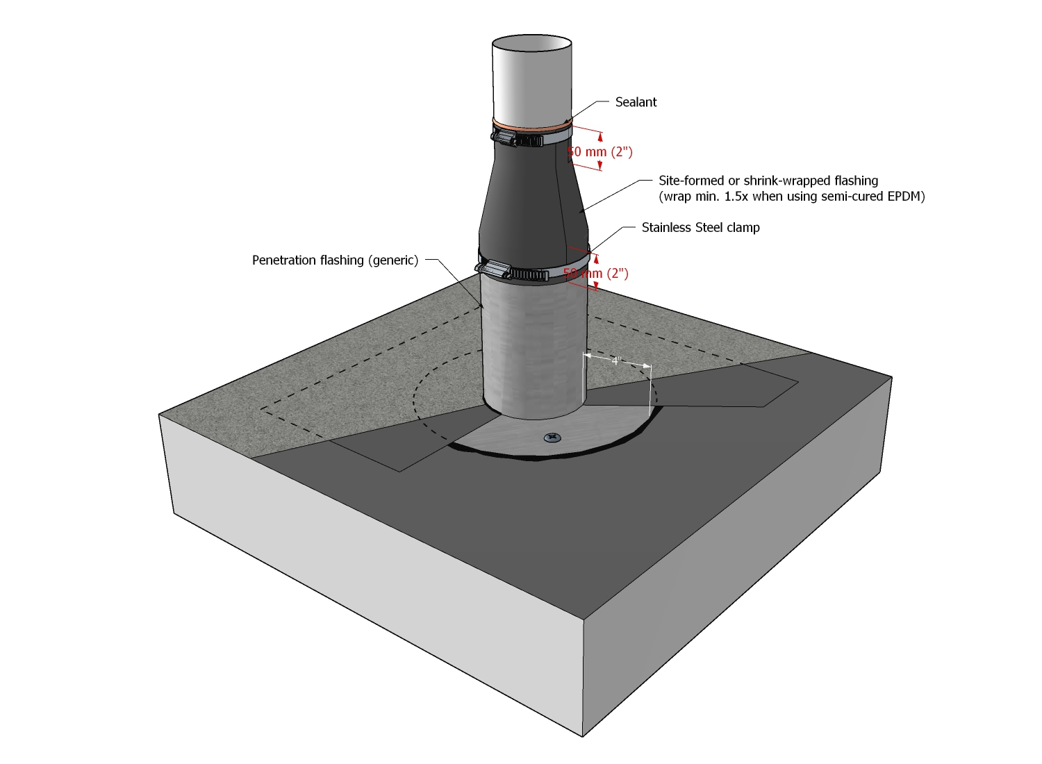
- Where a purpose-made flashing does not fit the penetration, the joint between the penetration and the flashing must be sealed using one of the following methods:
- using a site-formed non-bituminous flexible roof membrane storm collar, which is
- fashioned from semi-cured EPDM or its equivalent.
- installed free of wrinkles or fish-mouths.
- fully wrapped around the penetration and flashing and installed so that the membrane overlaps both the penetration and the flashing at least 50 mm (2").
- loosely wrapped around the penetration at least 1 ½ times or adhered to itself and overlapped at least 50 mm (2").
- clamped both at the top and at the bottom with stainless steel clamps set back from the membrane edge no more than 6.35 mm (1/4").
- with a heat-shrink wrapped membrane termination
- extending 50 mm (2”) onto both the penetration and the flashing.
- secured with a stainless-steel mechanical compression strap.
- using a site-formed non-bituminous flexible roof membrane storm collar, which is
- Galvanized, hot-welded flashings and vents may be installed on
- Uninsulated Systems or Conventionally Insulated Systems, provided the vents
- measure no more than 350 mm x 350 mm (14" x 14") in size, equal to approximately 0.12 meter squared (196 in.2) (Larger vents must be installed on curbs).
- are not located in or near a valley and are well drained.
- slopes less than 1:50 (1/4” in 12”), provided the vents are coated on all surfaces to a point at least 100 mm (4") above the finished waterproofing system. The coating must be
- an Accepted Material listed in this Manual and must be acceptable to the membrane manufacturer.
- applied evenly and with straight lines and must coat the penetration flashing at the membrane seal. Two cured coats are recommended for enhanced durability but are required for the RoofStar 15-Year Guarantee.
- Protected Membrane Roof Systems or Modified Protected Membrane Roof Systems, provided the vents are mounted on membrane-flashed curbs.
- Uninsulated Systems or Conventionally Insulated Systems, provided the vents
- When a pipe-type penetration is flashed with a cylindrical or conical purpose-made metal flashing that does not incorporate a fitted cap, the penetration must be protected immediately above the exposed top of the flashing with at least one properly fitted, level storm collar. All storm collars must be sealed at the top edge with an acceptable sealant.
This Standard applies to B-vent penetrations also. - Non-ferrous penetration flashings and vents may be located at the water plane in any assembly type. The use of lead jack flashings is not permitted for use with torch-applied membranes.
- Flashings with flanges must be installed after the field base membrane and
- embedded in mastic.
- securely fastened to the supporting deck structure or intermediate blocking.
- sealed to the base field membrane with a target patch that is
- cut from a base membrane.
- a single piece or, when the penetration is large, two pieces that must be joined with laps at least 150 mm (6”) in width.
- applied to a primed flashing flange.
- extending
- to the base of the flashing upstand.
- onto the roof field, by at least 100 mm (4”).
- aligned with the base field membrane runs, or oriented 45-degrees to the base field membrane.
- covered with cap membrane that terminates on the water plane at the base of a penetration flashing, and is sealed along the cut edge of the membrane with
- a compatible mastic embedded with granules.
- a reinforced 2-component liquid membrane flashing, applied in keeping with the standards found in 10.3.8 Liquid Membrane Flashing and 11.3.3.3 Liquid Membrane Flashing.
- should show continuous visible bleed-out of bitumen along all edges of the patch.
- Housekeeping pads situated on top of the finished waterproofing system and supporting a combined load less than 90 kg (200 lbs) must be separated from the roof with a bond-breaking layer (i.e. XPS insulation). Housekeeping pads supporting larger loads must conform to the standards for sleepers or equipment pads (11.1.2.2 (7)).
- Pourable sealant pockets should be used only when a purpose-made flashing is not available or practicable.
Regardless of the above method, a compatible sealant must be applied between the penetration and the collar or heat-shrink wrapping.
See Figure 11.3.3.1-1 below for an illustration of these standards.
|
3.3.2 Alternative Membrane Flashing Approaches
- When field membranes or flashing plies are heat-welded, or if required by construction sequencing, site personnel must assess the best approach.
- The project design and installation may incorporate one or more of the following alternatives to conventional membrane flashing methods:
- Curbs – see 10.3.3 Alternative Membrane Flashing Approaches for two optional methods.
- Other Penetrations:
- Before installing the base field membrane, a self-adhering or adhesive-applied base membrane flashing (“pre-flashing”), measuring at least 1m x 1m (39” x 39”), must be installed and centered around the penetration, on a suitable roof field substrate. The pre-flashing membrane must be cut to fit tightly around the penetration flashing.
- The base field membrane, which may be torch-applied, must be installed and tied into the pre-flashing (target patch), overlapping the patch by at least 150 mm (6”).
- The application standards for flashings with flanges must then be followed (see 11.3.3.1 General).
3.3.3 Liquid Membrane Flashing
- A RoofStar-accepted reinforced 2-component catalyzed polymethyl methacrylate (PMMA) liquid membrane flashing system may be used
- on the water plane.
- where sheet membrane flashing may not be practical or even possible.
- to terminate the top edge of sheet membrane flashing.
- for membrane reinforcement, i.e. at drain sump edges.
- where abrasion resistance is desirable.
- where resistance to membrane contamination is necessary.
- A RoofStar-accepted polyurethane and silicon-based single-component liquid membrane flashing system
- must be applied in two cured coats, unless otherwise permitted in this Standard.
- must be acceptable to the membrane manufacturer.
- may be used
- to coat galvanized flashings used in the water plane, provided the application follows the standards published in 11.3.3.1(10).
- to flash details more than 100 mm (4”) above the water plane, that cannot be sealed with sheet-type membranes.
- seal pre-curb dowels (see 14.1.2.3).
- must be fleece-reinforced between coats where
- a change in plane (angle) occurs.
- there is a joint between two supports and the liquid membrane must serve as a bridge.
- may not be used to terminate membranes, seal hard-flash penetrations at the water plane, or reinforce membranes against abrasion.
- Accessory PMMA detailers must be reinforced with chopped or loose fibres, and
- may not be used as a substitute for fleece-reinforced 2-component PMMA systems, where these are required or exclusively permitted.
- must be used at locations 100 mm (4”) or more above the water plane, but these limitations and requirements do not apply to details at the water plane, such as bolt heads, that cannot be properly sealed with a fleece-reinforced 2-component PMMA system.
- must not be used where movement is expected.
- The following standards pertain to the application of RoofStar-accepted reinforced 2-component catalyzed polymethyl methacrylate (PMMA) liquid membrane flashing systems:
- Use only liquid membrane flashings that are compatible with the primary membrane.
- Ensure proper preparation of the substrate, which must be clean, dry and free of contaminants. Preparation must follow the published procedures published by the flashing manufacturer.
- Liquid membranes must be applied with clean, straight, plumb edges. Therefore, mask the boundaries of areas to which liquid membrane will be applied, ensuring adequate coverage on all surfaces.
- For all applications,
- prime the substrate above the sheet membrane flashing, as directed by the manufacturer of the 2-part liquid membrane flashing system.
- apply a base layer of catalyzed liquid membrane resin within the area masked for coverage.
- reinforce the base coating with the manufacturer’s fleece and cut the fleece to size so that the fleece is set in from the masked area no more than 3 mm (1/8”).
- ensure the fleece is fully saturated with the liquid membrane, following the published instructions from the manufacturer.
- coat the fleece with a second application of catalyzed liquid membrane resin, covering the masked area.
- On vertical membrane terminations, apply the liquid membrane to provide no less than 50 mm (2") coverage, both above and below the sheet membrane termination.
- For use as a substitute for sheet membrane flashing, the reinforced liquid membrane flashing system must extend 200 mm (8”) both vertically and onto the field membrane.
- Application rates and guidelines issued by the manufacturer of the liquid membrane flashing product must be followed, unless superseded by these Standards.
- See Figure 11.3.3.3-1 for an illustration of these standards.
Figure 11.3.3.3-1 (Click to expand) 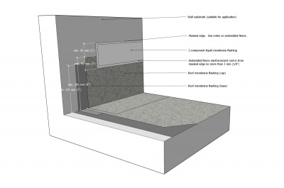

3.3.4 Sealant Pockets
- Sealing penetration flashings with sheet membranes or reinforced liquid membrane flashing should be considered impractical before pourable sealant pockets are used.
- When pourable sealant pockets are considered the last resort to seal a penetration,
- the penetration surfaces must be properly prepared following the sealant manufacturer’s instructions, to ensure a good bond between the penetration and the sealant.
- sealant pockets must be
- at least 50 mm (2”) deep.
- large enough to provide at least 25 mm (1”) of fillable space on all sides of the penetration.
- crowned with sealant to shed water.
- only the membrane manufacturer’s approved proprietary UV-stable urethane-based structural sealants may be used to fill sealant pockets.
- sealant pockets must be sealed to the roof membrane.
- a site-formed non-bituminous flexible roof membrane storm collar must be fitted and secured to the penetration with stainless steel clamps.
3.4 Guardrails
- Guardrails should be installed only on vertical surfaces; attachment of guardrails to a horizontal surface is strongly discouraged.
- Where guardrails are fastened through the top of copings, the base of the guardrail shall be flashed with a compatible reinforced membrane flashing material, applied according to the primary membrane flashing manufacturer’s specifications.
- Guardrails shall not direct water into a roof system by means of weep holes or the method of fastening, and mounts and flashings shall be installed at least 87.7 mm (3 ½”) above the roof surface, but in any event, a written Variance must be requested from the Guarantor.
For reference, see Construction Detail SBS 11.3.4 Guardrails.