
Difference between revisions of "Template:Part 3 (Waterproofing Roofs - SBS)"
Difference between revisions of "Template:Part 3 (Waterproofing Roofs - SBS)"
(→Mechanically Fastened Materials) |
(→General) |
||
| (14 intermediate revisions by the same user not shown) | |||
| Line 11: | Line 11: | ||
Refer to the [http://rpm.rcabc.org/index.php?title=Glossary '''Glossary'''] for further definitions of key terms used in this ''Manual''. | Refer to the [http://rpm.rcabc.org/index.php?title=Glossary '''Glossary'''] for further definitions of key terms used in this ''Manual''. | ||
| − | :;''CSA Standard'' | + | :;''CSA Standard'': means the ''CSA Standard A123.21 Standard test method for the dynamic wind uplift resistance of membrane-roofing systems'' (latest edition). |
;: | ;: | ||
| − | :;''Ballast | + | :;''Ballast'': means material (typically gravel or pavers) used for securing a ''system''. Gravel or pavers are considered ''overburden'' when they do not function as securement. |
;: | ;: | ||
| − | :;''Overburden'': | + | :;''Overburden'': {{hilite | means any material, structure or item of equipment that is placed on top of a ''waterproofing system''. Gravel or pavers constitute ''overburden'' when they do not function as securement.|| 2021-October-30 }}. |
;: | ;: | ||
| + | ==={{hilite | Intent || 2021-October-30 }}=== | ||
| + | {{hilite | In December 2018 the Province of British Columbia released a revised edition of the || 2021-October-30 }}[http://free.bcpublications.ca/civix/content/public/bcbc2018/?xsl=/templates/browse.xsl ''British Columbia Building Code''] {{hilite | (the "Code"), based on the 2015 ''National Building Code of Canada''. The 2018 Code includes a considerable expansion of the requirements in ''Division B, Part 4'' (see|| 2021-October-30 }} [http://free.bcpublications.ca/civix/document/id/public/bcbc2018/bcbc_2018dbp4s41r2 ''4.1 Structural Loads and Procedures'']{{hilite |, '''4.1.7 Wind Load''') applicable to the loads exerted on a roof system by wind. The careful reader will note that these Part 4 requirements apply to all Part 3 buildings and to some Part 9 structures|| 2021-October-30 }}. | ||
| + | |||
| + | {{hilite | While the expansion of Part 4 addresses the calculation of dynamic wind loads experienced by a roof assembly, Part 5 (Environmental Separation) specifies how a roof system should be secured to resist ''Specified Wind Loads'' (see || 2021-October-30}} [http://free.bcpublications.ca/civix/document/id/public/bcbc2018/bcbc_2018dbp5s52 ''5.2 Loads and Procedures'']{{hilite |, ''5.2.2.2 Determination of Wind Load'')|| 2021-October-30 }}. | ||
| + | |||
| + | {{hilite | Article 5.2.2.2 (Division B of the Code) applies almost exclusively to ''Conventionally Insulated Roof Systems'' and is specifically oriented to sheet membrane roof systems. While sheet membrane ''Conventionally Insulated Roof Systems'' are prolific and perhaps the most common type of waterproofing roof system, the Code offers little guidance for other roof types, including uninsulated roof systems, liquid membrane systems and systems insulated above the membrane (referred to as “inverted” or “protected”). This Standard incorporates design and construction guidance, even where the Code appears to offer little or no support|| 2021-October-30 }}. | ||
| + | |||
| + | {{hilite | Proper securement of the roof system, to resist wind uplift loads, is good practice. It also fulfills the design and construction objectives of the Code, to guard public safety, and it supports the design objectives of the '''''RoofStar Guarantee Program''''', to keep weather outside of the building. In this Part, the reader will find explanatory notes and aids in the design and construction of a roof intended to be Code-compliant|| 2021-October-30 }}. | ||
| + | |||
| + | ==={{hilite | Limitations and Exclusions || 2021-October-30 }}=== | ||
| + | {{hilite | Notwithstanding the intent of this Part, the materials presented herein are based on an interpretation of the Code and are not the Code itself. Therefore, the reader is responsible to exercise good judgement, and to read, understand and comply with the Code, as and how it applies to the reader’s particular ''project'' and its design requirements. Where the Code can be shown to exceed the requirements, guiding principles and recommendations of this Part or any related Part in this Standard, the Code shall prevail|| 2021-October-30 }}. | ||
| + | |||
| + | {{hilite | Compliance with this Part or the Code does not guarantee that a roof will not succumb to forces exerted by wind. Too many variables beyond the control of this Standard affect the wind resistance performance of a roof system, including (without limitation)|| 2021-October-30 }} | ||
| + | :a) {{hilite | the continuity or discontinuity of air and vapour control layers of the entire building enclosure|| 2021-October-30 }}. | ||
| + | :b) {{hilite | openings in the building (windows and doors, which are often occupant-controlled and not static)|| 2021-October-30 }}. | ||
| + | :c) {{hilite | wind strength which may exceed the codified numeric wind speed values used to calculate wind resistance for the roof system (ref. ''British Columbia Building Code'', Division B, Appendix C, Table C-1)|| 2021-October-30 }}. | ||
| + | |||
| + | {{hilite | Consequently, neither the '''''RoofStar Guarantee Program''''' nor the ''Contractor'' will accept any responsibility for damage to, or failure of, a roof system caused by wind|| 2021-October-30 }}. | ||
| + | <div id="WIND_DESIGN"></div> | ||
===Design=== | ===Design=== | ||
| − | Wind | + | {{hilite | Wind exerts tremendous forces on a ''roof system'', regardless of roof type. While wind is commonly experienced as a “pushing” force, wind also generates “negative” (pulling or “uplift”) forces, particularly on flat roofs. These powerful forces can, if the ''roof system'' is poorly secured to the building’s structural elements, detach a portion or all of a ''roof system'' from the building|| 2021-October-30 }}. |
| + | |||
| + | {{hilite | The Code refers to these calculated forces as ''Specified Wind Loads'', which act in concert with the “responses of the roof system…[and therefore] are time-and-space dependent, and thus are dynamic in nature.” (CSA Standard ''A123.21 Standard test method for the dynamic wind uplift resistance of membrane-roofing systems'' (latest edition), 4.1). Because of this dynamic interplay between loads and a building’s structural capacities (the load paths between the roof system and other structural elements of the building), the ''Design Authority'' must design a roof capable of effectively absorbing and mitigating ''Specified Wind Loads''|| 2021-October-30 }}. | ||
| + | |||
| + | {{hilite | As stated earlier, the calculation of ''Specified Wind Loads'' falls under ''Division B, Part 4 Structural Design,'' '''4.1.7 Wind Loads''', while the securement of the roof components system to resist ''Specified Wind Loads'' is governed by ''Division B, Part 5 Environmental Separation,'' '''5.2.2.2 Determination of Wind Load'''. ''Conventionally Insulated Roof Systems'' designed and constructed with sheet membranes must be secured using one of two options|| 2021-October-30 }}: | ||
| + | |||
| + | <ol> | ||
| + | <li>{{hilite | a ''Tested Assembly'' (a membrane roof system, together with a specified roof deck, tested for its wind resistance capabilities using CSA Standard ''A123.21 Standard test method for the dynamic wind uplift resistance of membrane-roofing systems'' (latest edition). It is important to note that ''CSA-A123.21'' is a test method developed only for ''Conventionally Insulated Roof Systems'' constructed with sheet membranes, and does not apply to other sheet membrane roof systems, or to roof systems constructed with other waterproofing materials such as liquid-applied membranes) || 2021-October-30 }}. | ||
| + | <li>{{hilite | an ''Assembly with Proven Past Performance'' (an existing, representative roof system, together with a specified roof deck, which is used as a “proven” pattern for securing a new roof system on the building under consideration; see '''3.3.3.1.2 Roof Assemblies with Proven Past Performance''')|| 2021-October-30 }}. | ||
| + | </li></ol> | ||
| + | <br> | ||
| + | {{hilite | When neither of those options is available to the ''Design Authority'', the '''''RoofStar Guarantee Standards''''' require the roof system to be secured using a custom engineered design (see '''3.3.3.1.3 Engineered Designs'''). Regardless of the approach used to secure a ''roof system'', proper securement is required by this Standard for all new roofs, and for both full and partial replacement roof systems|| 2021-October-30 }}. | ||
| − | + | {{hilite | This Part also sets out the requirements for|| 2021-October-30 }} | |
| − | + | <ol> | |
| − | + | <li>material substitution (applicable to ''Tested Assemblies''). | |
| − | + | <li>fastener and adhesive application (minimum numbers and spacing). | |
| + | <li>roofs installed with ''Overburden'', ''Protected Membrane Roof Systems'', and roofs where only part of the ''system'' must be replaced. | ||
| + | </li></ol> | ||
<br> | <br> | ||
{{hilite |''Protected'' and ''Modified Protected Membrane Roof Assemblies'', and uninsulated roof assemblies (with or without ballast) must be designed to resist the calculated ''Specified Wind Loads'', but their securement cannot be determined with the use of a ''Tested Assembly'' report, which pertains only to ''Conventionally Insulated Systems''. Rather, the ''Design Authority'' must refer to other resources to determine how to secure the roof against negative wind pressures. Some of those resources may be found in this Part|| 2020-October-22 }}. | {{hilite |''Protected'' and ''Modified Protected Membrane Roof Assemblies'', and uninsulated roof assemblies (with or without ballast) must be designed to resist the calculated ''Specified Wind Loads'', but their securement cannot be determined with the use of a ''Tested Assembly'' report, which pertains only to ''Conventionally Insulated Systems''. Rather, the ''Design Authority'' must refer to other resources to determine how to secure the roof against negative wind pressures. Some of those resources may be found in this Part|| 2020-October-22 }}. | ||
| − | {{hilite |Where a '''''RoofStar 15-year (Waterproofing | + | {{hilite |Where a '''''RoofStar 15-year (Roof Waterproofing) Guarantee''''' is specified, and enhanced ''roof system'' securement is required by the membrane manufacturer in order to meet their system warranty requirements (enhanced securement may exceed the securement required in a ''Tested Assembly'', an ''Assembly with Proven Past Performance'' or a custom-engineered securement), the higher securement requirements must be complied with in the design and construction of the ''Project''. See also '''1.3.1 RoofStar 15-Year Guarantee''' for further general requirements|| 2020-October-22 }}. |
{{hilite |The Standards, Guiding Principles and Recommendations in this sub-section|| 2020-October-22 }} are illustrated in the decision tree/flow chart shown as '''Figure 3.3''', and must be read in conjunction with '''3.3 Application'''. | {{hilite |The Standards, Guiding Principles and Recommendations in this sub-section|| 2020-October-22 }} are illustrated in the decision tree/flow chart shown as '''Figure 3.3''', and must be read in conjunction with '''3.3 Application'''. | ||
| Line 34: | Line 66: | ||
====<big>General</big>==== | ====<big>General</big>==== | ||
<ol> | <ol> | ||
| − | <li>The ''Design Authority'' is responsible for the proper calculation of ''Specified Wind Loads'' for a roof ''Waterproofing System'', regardless of its design, and must use the [https://www.nrc-cnrc.gc.ca/eng/services/windrci/agreement.html '''Wind-RCI online wind calculator'''] or, in the alternative, another method that is its equal or superior. This includes roofs that support an overburden, including ''Vegetated Roof Systems''. When the geometry of a building exceeds the capabilities of the Wind-RCI calculator, the ''Design Authority'' must calculate wind loads in accordance with the ''British Columbia Building Code, Division B, Part 4, 4.1.7 Wind Loads'', and in consultation with other sections of the ''British Columbia Building Code'' as they pertain to the determination of ''Specified Wind Loads''. Acceptance of a roof for a '''''RoofStar Guarantee''''' is predicated on the assumption that the ''Design Authority'' has performed Due Diligence with respect to ''Specified Wind Loads'' and the attachment methods for the roof assembly. | + | <li><u>The ''Design Authority'' is responsible for the proper calculation of ''Specified Wind Loads'' for a roof ''Waterproofing System'', regardless of its design</u>, and must use the [https://www.nrc-cnrc.gc.ca/eng/services/windrci/agreement.html '''Wind-RCI online wind calculator'''] or, in the alternative, another method that is its equal or superior {{hilite |(see|| 2021-October-30 }} [http://free.bcpublications.ca/civix/document/id/public/bcbc2018/bcbc_2018dcp2s22r2 '''2.2.1.2 Structural Design'''; ''The British Columbia Building Code, Division C, Part 2, Section 2.2 Administration'']. See also [http://free.bcpublications.ca/civix/document/id/public/bcbc2018/bcbc_2018dcp2n '''Notes to Part 2''']{{hilite |)|| 2021-October-30 }}. This includes roofs that support an overburden, including ''Vegetated Roof Systems''. When the geometry of a building exceeds the capabilities of the Wind-RCI calculator, the ''Design Authority'' must calculate wind loads in accordance with the ''British Columbia Building Code, Division B, Part 4, 4.1.7 Wind Loads'', and in consultation with other sections of the ''British Columbia Building Code'' as they pertain to the determination of ''Specified Wind Loads''. Acceptance of a roof for a '''''RoofStar Guarantee''''' is predicated on the assumption that the ''Design Authority'' has performed Due Diligence with respect to ''Specified Wind Loads'' and the attachment methods for the ''roof assembly''. |
<li>All roof ''Waterproofing Systems'' shall consist of the following three zones, illustrated in '''Figure 3.1'''. | <li>All roof ''Waterproofing Systems'' shall consist of the following three zones, illustrated in '''Figure 3.1'''. | ||
<ol> | <ol> | ||
<li>'''Field (F)''' – the interior of the roof bounded by the ''Edge'' and the ''Corners''. | <li>'''Field (F)''' – the interior of the roof bounded by the ''Edge'' and the ''Corners''. | ||
| − | <li>'''Edge (E)''' – defined as 10% of the building width or 40% of the building height, whichever is less. In no case will | + | <li>'''Edge (E)''' – defined as 10% of the building width or 40% of the building height, whichever is less. In no case will the ''Edge'' zone be less than 2.0 m (7'). |
<li>'''Corner (C)''' – part of the perimeter but not less than 2.0 m x 2.0 m (7’ x7’) in size. The ''Corner'' area is defined by the ''Edge'' in both directions at the corners.<br> | <li>'''Corner (C)''' – part of the perimeter but not less than 2.0 m x 2.0 m (7’ x7’) in size. The ''Corner'' area is defined by the ''Edge'' in both directions at the corners.<br> | ||
{| class="wikitable"; table style="background-color:white"; border="#A9A9A9;" | {| class="wikitable"; table style="background-color:white"; border="#A9A9A9;" | ||
| − | |+ ''' | + | |+ '''Figure 3.1''' (Click to expand) |
|- | |- | ||
| − | | [[File:Figure 3.1.jpg|link=http://rpm.rcabc.org/images/1/11/Figure_3.1.jpg | | + | | [[File:Figure 3.1.jpg|link=http://rpm.rcabc.org/images/1/11/Figure_3.1.jpg | 400 px]] |
|} | |} | ||
</li></ol> | </li></ol> | ||
<li>A ''Conventionally Insulated Systems'', and a ''Modified Protected Membrane Roof System'', constructed on a bare roof deck (new construction and replacement roofing) must be secured using | <li>A ''Conventionally Insulated Systems'', and a ''Modified Protected Membrane Roof System'', constructed on a bare roof deck (new construction and replacement roofing) must be secured using | ||
<ol> | <ol> | ||
| − | <li>a ''Tested Assembly'' (see '''3.3.1.1 Tested Assemblies'''). | + | <li>a ''Tested Assembly'' (see '''3.3.3.1.1 Tested Assemblies'''). |
<li>an ''Assembly with Proven Past Performance'' (see '''3.3.1.2 Roof Assemblies with Proven Past Performance'''). | <li>an ''Assembly with Proven Past Performance'' (see '''3.3.1.2 Roof Assemblies with Proven Past Performance'''). | ||
| − | <li>engineered methods and patterns (see | + | <li>engineered methods and patterns (see 3.3.1.3; also refer to the ''British Columbia Building Code, Division B'', ''Part 4'' and ''Part 5'' together with the ANSI/SPRI WD-1 methodology referenced in the ''British Columbia Building Code, Division B, Part 5'', [https://free.bcpublications.ca/civix/document/id/public/bcbc2018/bcbc_2018dbp5n Notes to Part 5], A-5.2.2.2.(4). |
</li></ol> | </li></ol> | ||
<li>The wind uplift resistance capabilities of the selected ''roof system'' must equal or exceed the ''Specified Wind Loads''. | <li>The wind uplift resistance capabilities of the selected ''roof system'' must equal or exceed the ''Specified Wind Loads''. | ||
| Line 59: | Line 91: | ||
<li>each roof area must be designed with ''Edge'' (E) zones on all sides, and ''Corner'' (C) zones at each outside and inside corner, irrespective of the elevation difference between the roofs.<br> | <li>each roof area must be designed with ''Edge'' (E) zones on all sides, and ''Corner'' (C) zones at each outside and inside corner, irrespective of the elevation difference between the roofs.<br> | ||
{| class="wikitable"; table style="background-color:white"; border="#A9A9A9;" | {| class="wikitable"; table style="background-color:white"; border="#A9A9A9;" | ||
| − | |+ ''' | + | |+ '''Figure 3.2''' (Click to expand) |
|- | |- | ||
| − | | [[File:Figure 3.2.jpg|link=http://rpm.rcabc.org/images/f/f4/Figure_3.2.jpg | | + | | [[File:Figure 3.2.jpg|link=http://rpm.rcabc.org/images/f/f4/Figure_3.2.jpg | 400 px]] |
|} | |} | ||
</li></ol> | </li></ol> | ||
| Line 70: | Line 102: | ||
<li>calculate the ''Specified Wind Loads'' for the roof. | <li>calculate the ''Specified Wind Loads'' for the roof. | ||
<li>determine whether or not securement of the remaining roof components (left in situ) is sufficient to resist the ''Specified Wind Loads''. | <li>determine whether or not securement of the remaining roof components (left in situ) is sufficient to resist the ''Specified Wind Loads''. | ||
| − | <li>determine a suitable method of securement or have the system of securement engineered. | + | <li>determine a suitable method of securement or have the ''system'' of securement engineered. |
| − | <li>calculate and design securement for any overburden.</ol></li> | + | <li>calculate and design securement for any ''overburden''.</ol></li> |
<br> | <br> | ||
See '''Figure 3.3''' for an illustration of this process. | See '''Figure 3.3''' for an illustration of this process. | ||
| Line 77: | Line 109: | ||
See also '''1.4.2 Replacement Roofing''', '''3.3.3 Partial Roof Replacements''' and '''Part 14 THE ROOF as a PLATFORM'''. | See also '''1.4.2 Replacement Roofing''', '''3.3.3 Partial Roof Replacements''' and '''Part 14 THE ROOF as a PLATFORM'''. | ||
<li><span class="recommended">When specifying securement for a partial roof replacement, mechanical fastening, when practicable, is the recommended method for securing new materials to an existing ''roof system''</span>. All other methods of securement must be designed and specified by the ''Design Authority''. | <li><span class="recommended">When specifying securement for a partial roof replacement, mechanical fastening, when practicable, is the recommended method for securing new materials to an existing ''roof system''</span>. All other methods of securement must be designed and specified by the ''Design Authority''. | ||
| − | <li><span class="principles">''Roof systems'' should be designed in conjunction with the electrical systems for the building, | + | <li><span class="principles">''Roof systems'' should be designed in conjunction with the electrical systems for the building, to avoid unnecessary interference with ''roof system'' securement</span>. <span class="recommended">Placement of cables and boxes in designated trays, suspended at least 38 mm (1 ½”) below a penetrable supporting ''deck'', is strongly recommended in order to avoid contact with roofing fasteners; fastener penetration may result in shock or fire hazard</span>. <span class="principles">Steel plates should not be used to shield conduit and boxes on top of or immediately beneath a penetrable ''deck'', because the plates will interfere with fastener placement and proper securement of the ''roof system''</span>. See also '''2.7 Electrical Cables and Boxes'''. |
<li>Securement of ''Water-shedding Systems'' shall be made in accordance with the requirements set out elsewhere in this ''Manual''. | <li>Securement of ''Water-shedding Systems'' shall be made in accordance with the requirements set out elsewhere in this ''Manual''. | ||
{| class="wikitable"; table style="background-color:white"; border="#A9A9A9;" | {| class="wikitable"; table style="background-color:white"; border="#A9A9A9;" | ||
| − | |+ ''' | + | |+ '''Figure 3.3''' (Click to expand) |
|- | |- | ||
| [[File:Figure 3.3.jpg|link=http://rpm.rcabc.org/images/6/6f/Figure_3.3.jpg |300 px]] | | [[File:Figure 3.3.jpg|link=http://rpm.rcabc.org/images/6/6f/Figure_3.3.jpg |300 px]] | ||
| Line 86: | Line 118: | ||
</li> | </li> | ||
</ol> | </ol> | ||
| − | + | <div id="WIND_DESIGN_BALLAST"></div> | |
====<big>Roofs with Ballast or Overburdens</big>==== | ====<big>Roofs with Ballast or Overburdens</big>==== | ||
'''NOTE''': the reader must consult the Design and Application requirements in '''12.1 Protected and Modified Protected Membrane Roof Systems''', together with requirements in '''Part 14 THE ROOF as a PLATFORM''' (with respect to ''Vegetated Roof Systems''). | '''NOTE''': the reader must consult the Design and Application requirements in '''12.1 Protected and Modified Protected Membrane Roof Systems''', together with requirements in '''Part 14 THE ROOF as a PLATFORM''' (with respect to ''Vegetated Roof Systems''). | ||
| − | #When vegetation and its growing media is intended as either ballast or '' | + | #When vegetation and its growing media is intended as either ballast or ''overburden'' on any membrane roof assembly, the ''Design Authority'' must, in addition to calculating the ''Specified Wind Loads'' for the ''roof assembly'', determine the ''Specified Wind Loads'' for the ''Vegetated Roof Systems'' (VRS), and the dimensions of the roof zones, using the [https://www.nrc-cnrc.gc.ca/eng/services/windrci/agreementvra.html '''WIND-VRA'''] online calculator tool or, in the alternative, another method that is its equal or superior. Note that this online resource applies only to buildings described on the Wind-RCI website as "low rise" and of moderate height (limited to 20 m or 65 feet) with a roof ''Waterproofing System''. Designing appropriate securement of a VRS on roofs taller than 20 m (65') or with slopes greater than 2:12 must be undertaken by a licensed design professional using current wind engineering practices, and must be acceptable to the ''Authority Having Jurisdiction'' (AHJ). Securement methods and details of a VRS, regardless of building height and roof slope, are the responsibility of the ''Design Authority''. |
#VRSs that are not modular, and VRSs on buildings that do not conform to the parameter of the Wind-VRA calculator, must be engineered to resist ''Specified Wind Loads''. | #VRSs that are not modular, and VRSs on buildings that do not conform to the parameter of the Wind-VRA calculator, must be engineered to resist ''Specified Wind Loads''. | ||
| − | #Ballasted loose-laid membrane roof | + | #Ballasted loose-laid membrane ''roof systems'', and ''systems'' designed as ''PMRAs'' or ''MPMRAs'' that utilize gravel ballast, must be designed for adequate securement by |
| − | ##calculating the ''Specified Wind Loads'' for the roof assembly. | + | ##calculating the ''Specified Wind Loads'' for the ''roof assembly''. |
##selecting the appropriate ballast using | ##selecting the appropriate ballast using | ||
###the RGC ballast guide (see '''3.3.2 Ballasted Roof Systems''', and '''12.1 Protected and Modified Protected Membrane Roof Systems'''). | ###the RGC ballast guide (see '''3.3.2 Ballasted Roof Systems''', and '''12.1 Protected and Modified Protected Membrane Roof Systems'''). | ||
###the [http://rpm.rcabc.org/images/2/2f/Dupont_508.2_Ballast_Design_Guide_for_PMR_Systems_%282020-02%29.pdf '''Dupont Tech Solutions 508.2 Ballast Design Guide for PMR Systems''']. | ###the [http://rpm.rcabc.org/images/2/2f/Dupont_508.2_Ballast_Design_Guide_for_PMR_Systems_%282020-02%29.pdf '''Dupont Tech Solutions 508.2 Ballast Design Guide for PMR Systems''']. | ||
| − | ###a custom-engineered system. | + | ###a custom-engineered ''system''. |
#When pavers are selected as ballast for a ''Protected'' or ''Modified Protected Membrane Roof System'', the ''Design Authority'' is responsible for determining the support and placement of pavers to resist wind uplift. | #When pavers are selected as ballast for a ''Protected'' or ''Modified Protected Membrane Roof System'', the ''Design Authority'' is responsible for determining the support and placement of pavers to resist wind uplift. | ||
#''Modified Protected Membrane Roof Systems'' must be designed for wind resistance following the requirements for ''Modified Protected Membrane Roof Systems'' and ''Conventionally Insulated Systems''. | #''Modified Protected Membrane Roof Systems'' must be designed for wind resistance following the requirements for ''Modified Protected Membrane Roof Systems'' and ''Conventionally Insulated Systems''. | ||
| − | #The ''Design Authority'' is responsible for determining the proper securement of any overburden intended for placement on top of the roof platform. For design, material and installation standards pertaining to roofs as platforms, refer in this ''Manual'' to '''Part 14 The ROOF as a PLATFORM'''. | + | #The ''Design Authority'' is responsible for determining the proper securement of any ''overburden'' intended for placement on top of the roof platform. For design, material and installation standards pertaining to roofs as platforms, refer in this ''Manual'' to '''Part 14 The ROOF as a PLATFORM'''. |
| + | <div id="SECUREMENT_MATERIALS"></div> | ||
==Materials== | ==Materials== | ||
===Material Substitutions in Tested Assemblies=== | ===Material Substitutions in Tested Assemblies=== | ||
| − | + | <span class="reference">{{hilite | ''Tested Assembly'' values (Dynamic Uplift Resistance) are predicated on a specific combination (system) of materials. Each material in the ''system'' possesses unique "cohesive properties" (internal strength and integrity) and is linked to the adjacent material in a particular way that may depend on a material’s unique "adhesive properties"|| 2021-October-30 }}. | |
| + | |||
| + | {{hilite | The substitution of material components in a ''Tested Assembly'' is not contemplated by ''CSA-A123.21'', but Annex F (a non-mandatory part of the CSA Standard, included at the back of the Standard document for information only) includes three decision processes for MARS, PARS and AARS assemblies, to guide the ''Design Authority'' when a substitution is desirable or necessary (ref. ''A123.21 Standard test method for the dynamic wind uplift resistance of membrane-roofing systems'', Annex F (informative) Component swap flow diagrams) || 2021-October-30 }}</span>. {{hilite | Using Annex F as a basis for guidance, the following standards and guiding principles apply for the purpose of issuing a '''''RoofStar Guarantee'''''|| 2021-October-30 }}: | ||
| + | |||
| + | <ol> | ||
| + | <li>{{hilite | When a manufacturer's ''Tested Assembly'' incorporates materials (and listed alternates) that are not part of the '''''RoofStar Guarantee Program''''', the ''Design Authority'' must identify appropriate substitutions for those materials from the list of|| 2021-October-30 }} [http://rpm.rcabc.org/index.php?title=Division_C:_Accepted_Materials '''RoofStar-accepted Materials'''] {{hilite | and consult the manufacturer concerning compatibility with the ''Tested Assembly''|| 2021-October-30 }}. | ||
| + | <li>{{hilite | All material substitutions, regardless of the reason for the substitution, must be supported in writing by a registered professional qualified to perform the work in Part 4 of the Code (ref. Article '''2.2.1.2 Structural Design'''; ''British Columbia Building Code, Division C, Part 2 Administrative Provisions, Section 2.2 Administration'')|| 2021-October-30 }}. | ||
| + | <li><span class="principles">{{hilite | Any material substitution should be limited to one (1) material component from the ''Tested Assembly'', but the substitution of more than one material component is permissible provided the substitution complies with the other requirements in this subsection|| 2021-October-30 }}</span>. | ||
| + | <li><span class="principles">{{hilite | Any material substitution should be made in keeping with the decision process flows for MARS, PARS and AARS assemblies published in CSA Standard ''A123.21 Standard test method for the dynamic wind uplift resistance of membrane-roofing systems (latest edition), Annex F''|| 2021-October-30 }}</span>. | ||
| + | <li>{{hilite | Because of its nature, a roof ''Assembly with Proven Past Performance'' does not qualify for material substitution|| 2021-October-30 }}. | ||
| + | </li></ol> | ||
===Gravel Ballast=== | ===Gravel Ballast=== | ||
| Line 126: | Line 169: | ||
<ol> | <ol> | ||
<li><span class="principles">pull-out strength.</span></li> | <li><span class="principles">pull-out strength.</span></li> | ||
| − | <li><span class="principles">corrosion resistance (contributing factors to fastener corrosion may include dissimilar metal contact, excessive building humidity, corrosive chemicals within components of the ''roof system'', or corrosive elements provided within the building envelope etc.)</span>.</li> | + | <li><span class="principles">corrosion resistance (contributing factors to fastener corrosion may include dissimilar metal contact, excessive building humidity, corrosive chemicals within components of the ''roof system'', or corrosive elements provided within the building envelope etc.)</span>. |
| − | </ol> | + | </li></ol> |
<li> Unless otherwise listed in the ''system'' components of a ''Tested Assembly'', self-drilling screws with recessed heads must be used in combination with plates as follows:<br> | <li> Unless otherwise listed in the ''system'' components of a ''Tested Assembly'', self-drilling screws with recessed heads must be used in combination with plates as follows:<br> | ||
{| class="wikitable" style="margin-left: 20pt; margin-right: auto;border-color:#E7E9E9;vertical-align:top;text-align:center;" | {| class="wikitable" style="margin-left: 20pt; margin-right: auto;border-color:#E7E9E9;vertical-align:top;text-align:center;" | ||
| Line 144: | Line 187: | ||
|}</li> | |}</li> | ||
<li>Adhesives listed in a selected ''Tested Assembly'' must be used to secure applicable layers within the ''roof system''. Adhesives may be substituted only with products listed in the ''Tested Assembly'' report.</li> | <li>Adhesives listed in a selected ''Tested Assembly'' must be used to secure applicable layers within the ''roof system''. Adhesives may be substituted only with products listed in the ''Tested Assembly'' report.</li> | ||
| − | <li>In the absence of a ''Tested Assembly'', or for adhered and partially adhered ''Assemblies with Proven Past Performance'', adhesives must be acceptable to the manufacturers of the roof assembly components.</li> | + | <li>In the absence of a ''Tested Assembly'', or for adhered and partially adhered ''Assemblies with Proven Past Performance'', adhesives must be acceptable to the manufacturers of the ''roof assembly'' components.</li> |
<li>Bitumen used as a hot-applied adhesive must be Type 3 or SEBS.</li> | <li>Bitumen used as a hot-applied adhesive must be Type 3 or SEBS.</li> | ||
</ol> | </ol> | ||
==Application== | ==Application== | ||
| − | ('''NOTE''': this | + | ('''NOTE''': this Section is critical for both the ''Design Authority'' and the ''Contractor'')<br> |
| − | A properly secured roof assembly is the product of three essential steps: | + | A properly secured ''roof assembly'' is the product of three essential steps: |
:{| class="wikitable" | :{| class="wikitable" | ||
|- | |- | ||
| '''Step 1''': Calculate the ''Specified Wind Loads'' for the roof. | | '''Step 1''': Calculate the ''Specified Wind Loads'' for the roof. | ||
| − | '''Step 2''': Select the type of ''Roof Assembly'' representative of the roof (conventionally insulated, or a Protected/Modified Protected Membrane Roof | + | '''Step 2''': Select the type of ''Roof Assembly'' representative of the roof (conventionally insulated, or a ''Protected/Modified Protected Membrane Roof System'').<br> |
| − | '''Step 3''': Design the securement system using available options, depending upon the type of assembly. | + | '''Step 3''': Design the securement ''system'' using available options, depending upon the type of ''assembly''. |
|} | |} | ||
| − | This section breaks down the '''''RoofStar Guarantee Standards''''' according to these three fundamental steps. The Standards published in this section are the minimum requirements, regardless of fastener or adhesive requirements in a ''Tested Assembly'', an ''Assembly with Proven Past Performance'', or any other assembly designed by other methodologies. | + | This section breaks down the '''''RoofStar Guarantee Standards''''' according to these three fundamental steps. The Standards published in this section are the minimum requirements, regardless of fastener or adhesive requirements in a ''Tested Assembly'', an ''Assembly with Proven Past Performance'', or any other ''assembly'' designed by other methodologies. |
===Step 1: Calculate Specified Wind Loads=== | ===Step 1: Calculate Specified Wind Loads=== | ||
| Line 166: | Line 209: | ||
| [[File:Figure 3.3.jpg|link=http://rpm.rcabc.org/images/6/6f/Figure_3.3.jpg |40 px]] | | [[File:Figure 3.3.jpg|link=http://rpm.rcabc.org/images/6/6f/Figure_3.3.jpg |40 px]] | ||
|} | |} | ||
| − | The information in this section may assist the ''Design Authority'' in better understanding the complexities of calculating ''Specified Wind Loads'', how wind affects a roof and each of its zones, and how to properly apply fastener or adhesive configurations for each zone and its respective | + | The information in this section may assist the ''Design Authority'' in better understanding the complexities of calculating ''Specified Wind Loads'', how wind affects a roof and each of its zones, and how to properly apply fastener or adhesive configurations for each zone and its respective ''Specified Wind Loads''. |
| − | |||
| − | |||
| + | <span class="reference">''Specified Wind Loads'' are forces exerted by wind which, in the case of a membrane ''roof system'', both push and lift the ''roof system'' or its components. Often, the upward or uplift forces are expressed as a negative value (negative pressure), but these are influenced by many variables including, without limitation, wind speed, building height, roof slope, wall openings, roof overhangs and ground roughness</span>. | ||
<span class="principles">''Specified Wind Loads'' for membrane roof ''Waterproofing Systems'' should be calculated using the available online[https://www.nrc-cnrc.gc.ca/eng/services/windrci/agreement.html '''Wind-RCI online wind calculator'''] or, in the alternative, another method that is its equal or superior (click [http://rpm.rcabc.org/images/5/5d/Sample_RCI_Report.pdf '''here'''] for a sample report).</span> When the Wind-RCI calculator is not suitable (as, for example, when a building exceeds 150 feet in height), the ''Design Authority'' must refer to the ''British Columbia Building Code, Division B, Parts 4'' and ''Part 5'' for further guidance. | <span class="principles">''Specified Wind Loads'' for membrane roof ''Waterproofing Systems'' should be calculated using the available online[https://www.nrc-cnrc.gc.ca/eng/services/windrci/agreement.html '''Wind-RCI online wind calculator'''] or, in the alternative, another method that is its equal or superior (click [http://rpm.rcabc.org/images/5/5d/Sample_RCI_Report.pdf '''here'''] for a sample report).</span> When the Wind-RCI calculator is not suitable (as, for example, when a building exceeds 150 feet in height), the ''Design Authority'' must refer to the ''British Columbia Building Code, Division B, Parts 4'' and ''Part 5'' for further guidance. | ||
| − | The report generated by the Wind-RCI calculator will specify the wind loads for the | + | The report generated by the Wind-RCI calculator will specify the wind loads for the ''Corners'', the ''Edge'' ("perimeter") and the ''Field''. These zone loads must be applied in Step 3 when determining the method of ''roof system'' securement. |
====Non-conforming Buildings==== | ====Non-conforming Buildings==== | ||
| Line 179: | Line 221: | ||
When a building’s dimensions are "non-conforming" and exceed the parameters of the Wind-RCI calculator, the following standards apply: | When a building’s dimensions are "non-conforming" and exceed the parameters of the Wind-RCI calculator, the following standards apply: | ||
#The ''Design Authority'' remains responsible for the proper design of a membrane roof ''Waterproofing System'', regardless of its method of securement. Refer to the ''British Columbia Building Code, Div. B, Parts 4'' and ''Part 5'' for further guidance. | #The ''Design Authority'' remains responsible for the proper design of a membrane roof ''Waterproofing System'', regardless of its method of securement. Refer to the ''British Columbia Building Code, Div. B, Parts 4'' and ''Part 5'' for further guidance. | ||
| − | #''Roof systems'' for non-conforming buildings must be engineered for proper securement to withstand | + | #''Roof systems'' for non-conforming buildings must be engineered for proper securement to withstand ''Specified Wind Loads''. |
#Non-conforming building ''roof systems'' must incorporate RoofStar-accepted materials. | #Non-conforming building ''roof systems'' must incorporate RoofStar-accepted materials. | ||
| Line 187: | Line 229: | ||
| [[File:Figure 3.3.jpg|link=http://rpm.rcabc.org/images/6/6f/Figure_3.3.jpg |40 px]] | | [[File:Figure 3.3.jpg|link=http://rpm.rcabc.org/images/6/6f/Figure_3.3.jpg |40 px]] | ||
|} | |} | ||
| − | Methods for securing the roof depend, in part, on the type of roof | + | Methods for securing the roof depend, in part, on the type of roof. ''Conventionally Insulated Systems'' that support any type of ''overburden'' should be treated like an uncovered roof, and secured accordingly (see below for options available to secure a ''Conventionally Insulated System''). When a ''Vegetated Roof System'' is specified, it is subject to different securement methods, based on its own ''Specified Wind Loads''. |
| − | Follow the path in '''Step 3''' that fits with your roof | + | ''Protected Membrane Roof Systems'' are secured with ballast. Guidance for these is provided below in '''3.3.3.2 Ballasted Roof Systems'''. |
| + | |||
| + | Follow the path in '''Step 3''' that fits with your ''roof system'' design.<br> | ||
===Step 3: Design Roof Assembly Securement=== | ===Step 3: Design Roof Assembly Securement=== | ||
| Line 199: | Line 243: | ||
:::*''Conventionally Insulated Systems'' | :::*''Conventionally Insulated Systems'' | ||
:::*Ballasted ''systems'' | :::*Ballasted ''systems'' | ||
| − | :::*Roofs supporting an '' | + | :::*Roofs supporting an ''overburden'' |
:::*Partially replaced roofs | :::*Partially replaced roofs | ||
====Conventionally Insulated Roof Assemblies==== | ====Conventionally Insulated Roof Assemblies==== | ||
Whether the ''Conventionally Insulated System'' is covered or uncovered, it must be secured using one of three methods. These are presented below as a progression from simplicity to complexity, and from low cost (for the ''Design Authority'') to high cost. | Whether the ''Conventionally Insulated System'' is covered or uncovered, it must be secured using one of three methods. These are presented below as a progression from simplicity to complexity, and from low cost (for the ''Design Authority'') to high cost. | ||
| − | If the intent of the ''Design Authority'' is to replace only a part of the existing roof system, see '''2.7.2''' for guidance and options. See also '''3.3.3.4''' below. | + | If the intent of the ''Design Authority'' is to replace only a part of the existing ''roof system'', see '''2.7.2''' for guidance and options. See also '''3.3.3.4''' below. |
=====<u><big>Tested Assemblies</big></u>===== | =====<u><big>Tested Assemblies</big></u>===== | ||
| Line 216: | Line 260: | ||
To find a ''Tested Assembly'', follow any of the links shown above. | To find a ''Tested Assembly'', follow any of the links shown above. | ||
| − | #<span class="recommended">The ''Design Authority'' is strongly encouraged to specify the application of a ''Tested Assembly'', for any design of a new | + | #<span class="recommended">The ''Design Authority'' is strongly encouraged to specify the application of a ''Tested Assembly'', for any design of a new or fully replaced membrane (''waterproofing system'') roof</span>. |
#The ''Design Authority'' must use only the test observation readings that have been adjusted for the Safety Factor. | #The ''Design Authority'' must use only the test observation readings that have been adjusted for the Safety Factor. | ||
#''Tested Assembly'' observation readings, reduced by the Safety Factor, must equal or exceed the highest ''Specified Wind Loads'' for the roof. This is called the ''Dynamic Uplift Resistance'' (DUR). | #''Tested Assembly'' observation readings, reduced by the Safety Factor, must equal or exceed the highest ''Specified Wind Loads'' for the roof. This is called the ''Dynamic Uplift Resistance'' (DUR). | ||
| Line 222: | Line 266: | ||
{| class="wikitable"; table style="background-color:white"; border="#A9A9A9;" | {| class="wikitable"; table style="background-color:white"; border="#A9A9A9;" | ||
| − | |+{{hilite | ''' | + | |+{{hilite | '''Figure 3.4''' (Click to expand) || 2020-July-3 }} |
|- | |- | ||
| [[File:Figure 3.4.jpg|link=http://rpm.rcabc.org/images/d/d8/Figure_3.4.jpg | 350 px]] | | [[File:Figure 3.4.jpg|link=http://rpm.rcabc.org/images/d/d8/Figure_3.4.jpg | 350 px]] | ||
| Line 231: | Line 275: | ||
#A roof ''Assembly with Proven Past Performance'' is a ''Conventionally Insulated System'' installed on a specific supporting deck that utilizes materials acceptable for the '''''RoofStar Guarantee Program''''', and which has demonstrated a proven track record of wind uplift resistance | #A roof ''Assembly with Proven Past Performance'' is a ''Conventionally Insulated System'' installed on a specific supporting deck that utilizes materials acceptable for the '''''RoofStar Guarantee Program''''', and which has demonstrated a proven track record of wind uplift resistance | ||
##for at least as long as the expected life of the new ''roof system''. | ##for at least as long as the expected life of the new ''roof system''. | ||
| − | ##for buildings, and in conditions, that are reasonably representative of the '' | + | ##for buildings, and in conditions, that are reasonably representative of the ''project'' the ''roof system'' will be specified for. |
| − | #Roof assemblies with | + | #Roof assemblies with ''Proven Past Performance'' |
##are an acceptable alternative to a ''Tested Assembly'' when | ##are an acceptable alternative to a ''Tested Assembly'' when | ||
###a ''Tested Assembly'' cannot be used. | ###a ''Tested Assembly'' cannot be used. | ||
| Line 243: | Line 287: | ||
##designed to exceed the ''Specified Wind Loads'' for the roof. | ##designed to exceed the ''Specified Wind Loads'' for the roof. | ||
##supported with a signed letter of assurance, issued by the ''Design Authority'' or the manufacturer of the ''Assembly with Proven Past Performance'', that it will perform as required. | ##supported with a signed letter of assurance, issued by the ''Design Authority'' or the manufacturer of the ''Assembly with Proven Past Performance'', that it will perform as required. | ||
| − | #Approvals issued by FM Global or another underwriter, for ''roof systems'' capable of resisting the ''Specified Wind Load'' of the ''Project'', may be given consideration by the '''''RoofStar Guarantee Program''''', but must be delivered to the ''Guarantor'' for review and written acceptance, along with a letter of assurance from the ''Design Authority'' or the manufacturer. | + | #Approvals issued by FM Global or another underwriter, for ''roof systems'' capable of resisting the ''Specified Wind Load'' of the ''Project'', may be given consideration by the '''''RoofStar Guarantee Program''''', but must be delivered to the '''''Guarantor''''' for review and written acceptance, along with a letter of assurance from the ''Design Authority'' or the manufacturer. |
=====<u><big>Engineered Designs</big></u>===== | =====<u><big>Engineered Designs</big></u>===== | ||
| − | When, for various reasons, a system of securement cannot be designed using either a ''Tested Assembly'' or an ''Assembly with Proven Past Performance'', the ''Design Authority'' must have the securement system designed by a qualified engineer following the requirements | + | When, for various reasons, a system of securement cannot be designed using either a ''Tested Assembly'' or an ''Assembly with Proven Past Performance'', the ''Design Authority'' must have the securement system designed by a qualified engineer following the requirements in [http://free.bcpublications.ca/civix/document/id/public/bcbc2018/bcbc_2018dcp2s22r2 '''2.2.1.2 Structural Design'''; ''The British Columbia Building Code, Division C, Part 2, Section 2.2 Administration'']'. |
====Ballasted Roof Systems==== | ====Ballasted Roof Systems==== | ||
'''NOTE''': the reader must consult the Design and Application requirements for '''12.1 Protected and Modified Protected Membrane Roof Systems''', and for '''Part 14 THE ROOF as a PLATFORM''' (with respect to ''Vegetated Roof Systems''). | '''NOTE''': the reader must consult the Design and Application requirements for '''12.1 Protected and Modified Protected Membrane Roof Systems''', and for '''Part 14 THE ROOF as a PLATFORM''' (with respect to ''Vegetated Roof Systems''). | ||
<ol> | <ol> | ||
| − | <li>''Roof systems'' secured with gravel ballast, pavers or both must be designed to resist | + | <li>''Roof systems'' secured with gravel ballast, pavers or both must be designed to resist ''Specified Wind Loads'', regardless of any ''overburden'' the design may call for. To facilitate resistance to ''Specified Wind Loads'', |
<ol> | <ol> | ||
<li>a filter fabric is required beneath gravel or paver ballast. | <li>a filter fabric is required beneath gravel or paver ballast. | ||
| Line 291: | Line 335: | ||
</li></ol> | </li></ol> | ||
<br> | <br> | ||
| − | :See also '''9.3.4 Loose-laid Ballasted Membranes'''. | + | ::See also '''9.3.4 Loose-laid Ballasted Membranes'''. |
====Roofs Supporting an Overburden==== | ====Roofs Supporting an Overburden==== | ||
| − | #Any supported '' | + | #Any supported ''overburden'' must be installed in keeping with the designed securement methods and systems specified by the ''Design Authority'', and must equal or exceed the ''Specified Wind Loads'' for the roof. |
#''Vegetated Roof Systems'' (VRSs) constructed in modules must be secured according to the methods specified by the ''Design Authority''. | #''Vegetated Roof Systems'' (VRSs) constructed in modules must be secured according to the methods specified by the ''Design Authority''. | ||
====Partial Roof Replacement==== | ====Partial Roof Replacement==== | ||
| − | #When only a portion of an existing ''roof system'' is specified for replacement, the new materials must be secured to resist wind | + | #When only a portion of an existing ''roof system'' is specified for replacement, the new materials must be secured to resist wind ''Specified Wind Loads''. See also '''1.4.2 Replacement Roofing'''. |
| − | #Mechanical fastening is the most reliable method for securing new materials installed over an existing roof assembly. When mechanical fastening is not practicable, the system of securement must conform to one of the following options: | + | #Mechanical fastening is the most reliable method for securing new materials installed over an existing ''roof assembly''. When mechanical fastening is not practicable, the ''system'' of securement must conform to one of the following options: |
#A custom-engineered design. | #A custom-engineered design. | ||
#A system design with ''Proven Past Performance'' (accompanied by a letter of assurance; see the requirements under '''3.3.3.1.2 Roof Assemblies with Proven Past Performance'''). | #A system design with ''Proven Past Performance'' (accompanied by a letter of assurance; see the requirements under '''3.3.3.1.2 Roof Assemblies with Proven Past Performance'''). | ||
| Line 309: | Line 353: | ||
<li>Multiple layers of insulation that are mechanically fastened must be secured together, as if they are a single layer. | <li>Multiple layers of insulation that are mechanically fastened must be secured together, as if they are a single layer. | ||
<li>Mechanical fasteners must penetrate | <li>Mechanical fasteners must penetrate | ||
| + | <ol> | ||
| + | <li>{{hilite | through the bottom surface of|| 2021-October-30 }} | ||
<ol> | <ol> | ||
<li>steel ''decks'' at least 20 mm (3/4") – <span class="principles">fasteners should penetrate the top flutes only</span>. | <li>steel ''decks'' at least 20 mm (3/4") – <span class="principles">fasteners should penetrate the top flutes only</span>. | ||
| − | <li> | + | <li>{{hilite | plywood sheathing by at least 19 mm (3/4")|| 2021-October-30 }}. |
| − | <li> | + | </li></ol> |
| + | <li>{{hilite | into solid dimensional lumber or concrete by at least 25 mm (1")|| 2021-October-30 }}. | ||
</li></ol> | </li></ol> | ||
| + | <br> | ||
| + | {{hilite | See '''Figure 3.5'''|| 2021-October-30 }}. | ||
| + | {| class="wikitable"; table style="background-color:white"; border="#A9A9A9;" | ||
| + | |+ '''Figure 3.5''' (Click to expand) | ||
| + | |- | ||
| + | | [[File:Figure 3.5.jpg|link=http://rpm.rcabc.org/images/9/95/Figure_3.5.jpg| 500 px]] | ||
| + | |} | ||
<br> | <br> | ||
These Standards may be exceeded by the fastener manufacturer’s published requirements. | These Standards may be exceeded by the fastener manufacturer’s published requirements. | ||
| − | |||
<li>When mechanically attached membranes are installed together with new insulation, the insulation assembly {{hilite | (with or without an ''insulation overlay'')|| 2020-July-3 }} must be held in place independently from the membrane, with no fewer than four (4) fasteners per panel. | <li>When mechanically attached membranes are installed together with new insulation, the insulation assembly {{hilite | (with or without an ''insulation overlay'')|| 2020-July-3 }} must be held in place independently from the membrane, with no fewer than four (4) fasteners per panel. | ||
| − | <li>'''Table 3.3''' shows the minimum required number of fasteners, unless otherwise specified by a ''Tested Assembly'', an ''Assembly with Proven Past Performance'', or a custom-engineered assembly. Also see the required patterns, displayed below the table: | + | <li>'''Table 3.3''' shows the minimum required number of fasteners, unless otherwise specified by a ''Tested Assembly'', an ''Assembly with Proven Past Performance'', or a custom-engineered ''assembly''. Also see the required patterns, displayed below the table: |
<ol> | <ol> | ||
<li>Fasteners must be installed no more than 150 mm (6”) from panel corners, measured from each edge of the panel. | <li>Fasteners must be installed no more than 150 mm (6”) from panel corners, measured from each edge of the panel. | ||
| − | <li>Fasteners used to secure boards from curling, or to secure boards at slope transitions, shall be in addition to the minimum number of fasteners and plates required by the patterns shown in '''Table 3.4 | + | <li>Fasteners used to secure boards from curling, or to secure boards at slope transitions, shall be in addition to the minimum number of fasteners and plates required by the patterns shown in '''Table 3.4'''.</li></ol> |
| + | </li></ol> | ||
</li></ol> | </li></ol> | ||
:{| class="wikitable" style="text-align: left; margin-left: 20pt; margin-right: auto; border: none;" | :{| class="wikitable" style="text-align: left; margin-left: 20pt; margin-right: auto; border: none;" | ||
| Line 383: | Line 437: | ||
! colspan="1" rowspan="1" style="width: 300px; vertical-align:top;text-align:center;" | Corner | ! colspan="1" rowspan="1" style="width: 300px; vertical-align:top;text-align:center;" | Corner | ||
|- | |- | ||
| − | | [[File:Table 3.4 - 4x8 (4 fasteners).jpg | link=http://rpm.rcabc.org/images/4/4f/Table_3.4_-_4x8_%284_fasteners%29.jpg | 300 px]] '''4 Fasteners''' || [[File:Table 3.4 - 4x8 (4 fasteners).jpg | link=http://rpm.rcabc.org/images/4/4f/Table_3.4_-_4x8_%284_fasteners%29.jpg | 300 px]] '''4 Fasteners''' || [[File:Table 3.4 - 4x8 (4 fasteners).jpg | link=http://rpm.rcabc.org/images/4/4f/Table_3.4_-_4x8_%284_fasteners%29.jpg | 300 px]] '''4 Fasteners''' | + | | style="width: 100px;vertical-align:top;text-align:center;background: #fff;" | [[File:Table 3.4 - 4x8 (4 fasteners).jpg | link=http://rpm.rcabc.org/images/4/4f/Table_3.4_-_4x8_%284_fasteners%29.jpg | 300 px]] '''4 Fasteners''' || style="width: 100px;vertical-align:top;text-align:center;background: #fff;" | [[File:Table 3.4 - 4x8 (4 fasteners).jpg | link=http://rpm.rcabc.org/images/4/4f/Table_3.4_-_4x8_%284_fasteners%29.jpg | 300 px]] '''4 Fasteners''' || style="width: 100px;vertical-align:top;text-align:center;background: #fff;" | [[File:Table 3.4 - 4x8 (4 fasteners).jpg | link=http://rpm.rcabc.org/images/4/4f/Table_3.4_-_4x8_%284_fasteners%29.jpg | 300 px]] '''4 Fasteners''' |
| + | |- | ||
| + | ! colspan="1" rowspan="1" style="width: 300px; vertical-align:top;text-align:center;" | Field | ||
| + | ! colspan="1" rowspan="1" style="width: 300px; vertical-align:top;text-align:center;" | Perimeter | ||
| + | ! colspan="1" rowspan="1" style="width: 300px; vertical-align:top;text-align:center;" | Corner | ||
|- | |- | ||
| − | | [[File:Table 3.4 - 4x8 (8 fasteners).jpg | link=http://rpm.rcabc.org/images/b/b7/Table_3.4_-_4x8_%288_fasteners%29.jpg | 300 px]] '''8 Fasteners''' || [[File:Table 3.4 - 4x8 (12 fasteners).jpg | link=http://rpm.rcabc.org/images/c/c9/Table_3.4_-_4x8_%2812_fasteners%29.jpg | 300 px]] '''12 Fasteners''' || [[File:Table 3.4 - 4x8 (15 fasteners).jpg | link=http://rpm.rcabc.org/images/5/58/Table_3.4_-_4x8_%2815_fasteners%29.jpg | 300 px]] '''15 Fasteners''' | + | | style="width: 100px;vertical-align:top;text-align:center;background: #fff;" | [[File:Table 3.4 - 4x8 (8 fasteners).jpg | link=http://rpm.rcabc.org/images/b/b7/Table_3.4_-_4x8_%288_fasteners%29.jpg | 300 px]] '''8 Fasteners''' || style="width: 100px;vertical-align:top;text-align:center;background: #fff;" | [[File:Table 3.4 - 4x8 (12 fasteners).jpg | link=http://rpm.rcabc.org/images/c/c9/Table_3.4_-_4x8_%2812_fasteners%29.jpg | 300 px]] '''12 Fasteners''' || style="width: 100px;vertical-align:top;text-align:center;background: #fff;" | [[File:Table 3.4 - 4x8 (15 fasteners).jpg | link=http://rpm.rcabc.org/images/5/58/Table_3.4_-_4x8_%2815_fasteners%29.jpg | 300 px]] '''15 Fasteners''' |
|- | |- | ||
|} | |} | ||
| Line 395: | Line 453: | ||
! colspan="1" rowspan="1" style="width: 300px; vertical-align:top;text-align:center;" | Corner | ! colspan="1" rowspan="1" style="width: 300px; vertical-align:top;text-align:center;" | Corner | ||
|- | |- | ||
| − | | [[File:Table 3.4 - 4x4 (5 fasteners).jpg | link=http://rpm.rcabc.org/images/f/f6/Table_3.4_-_4x4_%285_fasteners%29.jpg | 300 px]] '''5 Fasteners''' || [[File:Table 3.4 - 4x4 (6 fasteners).jpg | link=http://rpm.rcabc.org/images/7/76/Table_3.4_-_4x4_%286_fasteners%29.jpg | 300 px]] '''6 Fasteners''' || [[File:Table 3.4 - 4x4 (8 fasteners).jpg | link=http://rpm.rcabc.org/images/7/76/Table_3.4_-_4x4_%288_fasteners%29.jpg | 300 px]] '''8 Fasteners''' | + | | style="width: 100px;vertical-align:top;text-align:center;background: #fff;" | [[File:Table 3.4 - 4x4 (5 fasteners).jpg | link=http://rpm.rcabc.org/images/f/f6/Table_3.4_-_4x4_%285_fasteners%29.jpg | 300 px]] '''5 Fasteners''' || style="width: 100px;vertical-align:top;text-align:center;background: #fff;" | [[File:Table 3.4 - 4x4 (6 fasteners).jpg | link=http://rpm.rcabc.org/images/7/76/Table_3.4_-_4x4_%286_fasteners%29.jpg | 300 px]] '''6 Fasteners''' || style="width: 100px;vertical-align:top;text-align:center;background: #fff;" | [[File:Table 3.4 - 4x4 (8 fasteners).jpg | link=http://rpm.rcabc.org/images/7/76/Table_3.4_-_4x4_%288_fasteners%29.jpg | 300 px]] '''8 Fasteners''' |
|- | |- | ||
|} | |} | ||
| Line 407: | Line 465: | ||
! colspan="1" rowspan="1" style="width: 300px; vertical-align:top;text-align:center;" | Corner | ! colspan="1" rowspan="1" style="width: 300px; vertical-align:top;text-align:center;" | Corner | ||
|- | |- | ||
| − | | [[File:Table 3.5 - 4x6 (6 fasteners).jpg | link=http://rpm.rcabc.org/images/9/94/Table_3.5_-_4x6_%286_fasteners%29.jpg | 300 px]] '''6 Fasteners''' || [[File:Table 3.5 - 4x6 (8 fasteners).jpg | link=http://rpm.rcabc.org/images/8/88/Table_3.5_-_4x6_%288_fasteners%29.jpg | 300px]] '''8 Fasteners''' || [[File:Table 3.5 - 4x6 (12 fasteners).jpg | link=http://rpm.rcabc.org/images/c/c7/Table_3.5_-_4x6_%2812_fasteners%29.jpg | 300 px]] '''12 Fasteners''' | + | | style="width: 100px;vertical-align:top;text-align:center;background: #fff;" | [[File:Table 3.5 - 4x6 (6 fasteners).jpg | link=http://rpm.rcabc.org/images/9/94/Table_3.5_-_4x6_%286_fasteners%29.jpg | 300 px]] '''6 Fasteners''' || style="width: 100px;vertical-align:top;text-align:center;background: #fff;" | [[File:Table 3.5 - 4x6 (8 fasteners).jpg | link=http://rpm.rcabc.org/images/8/88/Table_3.5_-_4x6_%288_fasteners%29.jpg | 300px]] '''8 Fasteners''' || style="width: 100px;vertical-align:top;text-align:center;background: #fff;" | [[File:Table 3.5 - 4x6 (12 fasteners).jpg | link=http://rpm.rcabc.org/images/c/c7/Table_3.5_-_4x6_%2812_fasteners%29.jpg | 300 px]] '''12 Fasteners''' |
|- | |- | ||
! colspan="3" rowspan="1" style="width: 500px;vertical-align:centre;text-align:center;background: #A9A9A9;" | 900mm x 1200mm (3’ x 4’) | ! colspan="3" rowspan="1" style="width: 500px;vertical-align:centre;text-align:center;background: #A9A9A9;" | 900mm x 1200mm (3’ x 4’) | ||
| Line 415: | Line 473: | ||
! colspan="1" rowspan="1" style="width: 300px; vertical-align:top;text-align:center;" | Corner | ! colspan="1" rowspan="1" style="width: 300px; vertical-align:top;text-align:center;" | Corner | ||
|- | |- | ||
| − | | [[File:Table 3.5 - 3x4 (4 fasteners).jpg | link=http://rpm.rcabc.org/images/9/9f/Table_3.5_-_3x4_%284_fasteners%29.jpg | 300 px]] '''4 Fasteners''' || [[File:Table 3.5 - 3x4 (6 fasteners).jpg | link=http://rpm.rcabc.org/images/d/d1/Table_3.5_-_3x4_%286_fasteners%29.jpg | 300 px]] '''6 Fasteners''' || [[File:Table 3.5 - 3x4 (7 fasteners).jpg | link=http://rpm.rcabc.org/images/e/ed/Table_3.5_-_3x4_%287_fasteners%29.jpg | 300 px]] '''7 Fasteners''' | + | | style="width: 100px;vertical-align:top;text-align:center;background: #fff;" | [[File:Table 3.5 - 3x4 (4 fasteners).jpg | link=http://rpm.rcabc.org/images/9/9f/Table_3.5_-_3x4_%284_fasteners%29.jpg | 300 px]] '''4 Fasteners''' || style="width: 100px;vertical-align:top;text-align:center;background: #fff;" | [[File:Table 3.5 - 3x4 (6 fasteners).jpg | link=http://rpm.rcabc.org/images/d/d1/Table_3.5_-_3x4_%286_fasteners%29.jpg | 300 px]] '''6 Fasteners''' || style="width: 100px;vertical-align:top;text-align:center;background: #fff;" | [[File:Table 3.5 - 3x4 (7 fasteners).jpg | link=http://rpm.rcabc.org/images/e/ed/Table_3.5_-_3x4_%287_fasteners%29.jpg | 300 px]] '''7 Fasteners''' |
|- | |- | ||
! colspan="3" rowspan="1" style="width: 500px;vertical-align:centre;text-align:center;background: #A9A9A9;" | 600mm x 2400mm (2’ x 8’) | ! colspan="3" rowspan="1" style="width: 500px;vertical-align:centre;text-align:center;background: #A9A9A9;" | 600mm x 2400mm (2’ x 8’) | ||
| Line 423: | Line 481: | ||
! colspan="1" rowspan="1" style="width: 300px; vertical-align:top;text-align:center;" | Corner | ! colspan="1" rowspan="1" style="width: 300px; vertical-align:top;text-align:center;" | Corner | ||
|- | |- | ||
| − | | [[File:Table 3.5 - 2x8 (5 fasteners).jpg | link=http://rpm.rcabc.org/images/3/39/Table_3.5_-_2x8_%285_fasteners%29.jpg | 300 px]] '''5 Fasteners''' || [[File:Table 3.5 - 2x8 (6 fasteners).jpg | link=http://rpm.rcabc.org/images/6/69/Table_3.5_-_2x8_%286_fasteners%29.jpg | 300 px]] '''6 Fasteners''' || [[File:Table 3.5 - 2x8 (8 fasteners).jpg | link=http://rpm.rcabc.org/images/7/76/Table_3.5_-_2x8_%288_fasteners%29.jpg | 300 px]] '''8 Fasteners''' | + | | style="width: 100px;vertical-align:top;text-align:center;background: #fff;" | [[File:Table 3.5 - 2x8 (5 fasteners).jpg | link=http://rpm.rcabc.org/images/3/39/Table_3.5_-_2x8_%285_fasteners%29.jpg | 300 px]] '''5 Fasteners''' || style="width: 100px;vertical-align:top;text-align:center;background: #fff;" | [[File:Table 3.5 - 2x8 (6 fasteners).jpg | link=http://rpm.rcabc.org/images/6/69/Table_3.5_-_2x8_%286_fasteners%29.jpg | 300 px]] '''6 Fasteners''' || style="width: 100px;vertical-align:top;text-align:center;background: #fff;" | [[File:Table 3.5 - 2x8 (8 fasteners).jpg | link=http://rpm.rcabc.org/images/7/76/Table_3.5_-_2x8_%288_fasteners%29.jpg | 300 px]] '''8 Fasteners''' |
|- | |- | ||
! colspan="3" rowspan="1" style="width: 500px;vertical-align:centre;text-align:center;background: #A9A9A9;" | 600mm x 1200mm (2’ x 4’) | ! colspan="3" rowspan="1" style="width: 500px;vertical-align:centre;text-align:center;background: #A9A9A9;" | 600mm x 1200mm (2’ x 4’) | ||
| Line 431: | Line 489: | ||
! colspan="1" rowspan="1" style="width: 300px; vertical-align:top;text-align:center;" | Corner | ! colspan="1" rowspan="1" style="width: 300px; vertical-align:top;text-align:center;" | Corner | ||
|- | |- | ||
| − | | [[File:Table 3.5 - 2x4 (4 fasteners).jpg | link=http://rpm.rcabc.org/images/f/f9/Table_3.5_-_2x4_%284_fasteners%29.jpg | 300 px]] '''4 Fasteners''' || [[File:Table 3.5 - 2x4 (4 fasteners).jpg | link=http://rpm.rcabc.org/images/f/f9/Table_3.5_-_2x4_%284_fasteners%29.jpg | 300 px]] '''4 Fasteners''' || [[File:Table 3.5 - 2x4 (5 fasteners).jpg | link=http://rpm.rcabc.org/images/b/b3/Table_3.5_-_2x4_%285_fasteners%29.jpg | 300 px]] '''5 Fasteners''' | + | | style="width: 100px;vertical-align:top;text-align:center;background: #fff;" | [[File:Table 3.5 - 2x4 (4 fasteners).jpg | link=http://rpm.rcabc.org/images/f/f9/Table_3.5_-_2x4_%284_fasteners%29.jpg | 300 px]] '''4 Fasteners''' || style="width: 100px;vertical-align:top;text-align:center;background: #fff;" | [[File:Table 3.5 - 2x4 (4 fasteners).jpg | link=http://rpm.rcabc.org/images/f/f9/Table_3.5_-_2x4_%284_fasteners%29.jpg | 300 px]] '''4 Fasteners''' || style="width: 100px;vertical-align:top;text-align:center;background: #fff;" | [[File:Table 3.5 - 2x4 (5 fasteners).jpg | link=http://rpm.rcabc.org/images/b/b3/Table_3.5_-_2x4_%285_fasteners%29.jpg | 300 px]] '''5 Fasteners''' |
|- | |- | ||
|} | |} | ||
| Line 439: | Line 497: | ||
=====<big><u>Adhesive Applied Materials</u></big>===== | =====<big><u>Adhesive Applied Materials</u></big>===== | ||
#<span class="principles">Adhesives may be used to secure new roofing materials to an existing ''roof system''</span>, provided the specific application procedures and methods are engineered by or for the ''Design Authority''. | #<span class="principles">Adhesives may be used to secure new roofing materials to an existing ''roof system''</span>, provided the specific application procedures and methods are engineered by or for the ''Design Authority''. | ||
| − | #Notwithstanding the above, the minimum requirements set out in '''7.3.2 | + | #Notwithstanding the above, the minimum requirements set out in '''7.3.2.4''' apply. |
Latest revision as of 18:08, 12 November 2021

Click on the gif above to see the full high-definition video, which illustrates why roof system attachment standards matter (NOTE: the system shown in the video represents a mechanically fastened EPDM roof, constructed to RoofStar Guarantee Standards. The membrane "flutter" in wind is normal for this type of roof system).
1 General
1.1 Definitions
Refer to the Glossary for further definitions of key terms used in this Manual.
- CSA Standard
- means the CSA Standard A123.21 Standard test method for the dynamic wind uplift resistance of membrane-roofing systems (latest edition).
- Ballast
- means material (typically gravel or pavers) used for securing a system. Gravel or pavers are considered overburden when they do not function as securement.
- Overburden
- means any material, structure or item of equipment that is placed on top of a waterproofing system. Gravel or pavers constitute overburden when they do not function as securement..
1.2 Intent
In December 2018 the Province of British Columbia released a revised edition of theBritish Columbia Building Code (the "Code"), based on the 2015 National Building Code of Canada. The 2018 Code includes a considerable expansion of the requirements in Division B, Part 4 (see 4.1 Structural Loads and Procedures, 4.1.7 Wind Load) applicable to the loads exerted on a roof system by wind. The careful reader will note that these Part 4 requirements apply to all Part 3 buildings and to some Part 9 structures.
While the expansion of Part 4 addresses the calculation of dynamic wind loads experienced by a roof assembly, Part 5 (Environmental Separation) specifies how a roof system should be secured to resist Specified Wind Loads (see 5.2 Loads and Procedures, 5.2.2.2 Determination of Wind Load).
Article 5.2.2.2 (Division B of the Code) applies almost exclusively to Conventionally Insulated Roof Systems and is specifically oriented to sheet membrane roof systems. While sheet membrane Conventionally Insulated Roof Systems are prolific and perhaps the most common type of waterproofing roof system, the Code offers little guidance for other roof types, including uninsulated roof systems, liquid membrane systems and systems insulated above the membrane (referred to as “inverted” or “protected”). This Standard incorporates design and construction guidance, even where the Code appears to offer little or no support.
Proper securement of the roof system, to resist wind uplift loads, is good practice. It also fulfills the design and construction objectives of the Code, to guard public safety, and it supports the design objectives of the RoofStar Guarantee Program, to keep weather outside of the building. In this Part, the reader will find explanatory notes and aids in the design and construction of a roof intended to be Code-compliant.
1.3 Limitations and Exclusions
Notwithstanding the intent of this Part, the materials presented herein are based on an interpretation of the Code and are not the Code itself. Therefore, the reader is responsible to exercise good judgement, and to read, understand and comply with the Code, as and how it applies to the reader’s particular project and its design requirements. Where the Code can be shown to exceed the requirements, guiding principles and recommendations of this Part or any related Part in this Standard, the Code shall prevail.
Compliance with this Part or the Code does not guarantee that a roof will not succumb to forces exerted by wind. Too many variables beyond the control of this Standard affect the wind resistance performance of a roof system, including (without limitation)
- a) the continuity or discontinuity of air and vapour control layers of the entire building enclosure.
- b) openings in the building (windows and doors, which are often occupant-controlled and not static).
- c) wind strength which may exceed the codified numeric wind speed values used to calculate wind resistance for the roof system (ref. British Columbia Building Code, Division B, Appendix C, Table C-1).
Consequently, neither the RoofStar Guarantee Program nor the Contractor will accept any responsibility for damage to, or failure of, a roof system caused by wind.
1.4 Design
Wind exerts tremendous forces on a roof system, regardless of roof type. While wind is commonly experienced as a “pushing” force, wind also generates “negative” (pulling or “uplift”) forces, particularly on flat roofs. These powerful forces can, if the roof system is poorly secured to the building’s structural elements, detach a portion or all of a roof system from the building.
The Code refers to these calculated forces as Specified Wind Loads, which act in concert with the “responses of the roof system…[and therefore] are time-and-space dependent, and thus are dynamic in nature.” (CSA Standard A123.21 Standard test method for the dynamic wind uplift resistance of membrane-roofing systems (latest edition), 4.1). Because of this dynamic interplay between loads and a building’s structural capacities (the load paths between the roof system and other structural elements of the building), the Design Authority must design a roof capable of effectively absorbing and mitigating Specified Wind Loads.
As stated earlier, the calculation of Specified Wind Loads falls under Division B, Part 4 Structural Design, 4.1.7 Wind Loads, while the securement of the roof components system to resist Specified Wind Loads is governed by Division B, Part 5 Environmental Separation, 5.2.2.2 Determination of Wind Load. Conventionally Insulated Roof Systems designed and constructed with sheet membranes must be secured using one of two options:
- a Tested Assembly (a membrane roof system, together with a specified roof deck, tested for its wind resistance capabilities using CSA Standard A123.21 Standard test method for the dynamic wind uplift resistance of membrane-roofing systems (latest edition). It is important to note that CSA-A123.21 is a test method developed only for Conventionally Insulated Roof Systems constructed with sheet membranes, and does not apply to other sheet membrane roof systems, or to roof systems constructed with other waterproofing materials such as liquid-applied membranes).
- an Assembly with Proven Past Performance (an existing, representative roof system, together with a specified roof deck, which is used as a “proven” pattern for securing a new roof system on the building under consideration; see 3.3.3.1.2 Roof Assemblies with Proven Past Performance).
When neither of those options is available to the Design Authority, the RoofStar Guarantee Standards require the roof system to be secured using a custom engineered design (see 3.3.3.1.3 Engineered Designs). Regardless of the approach used to secure a roof system, proper securement is required by this Standard for all new roofs, and for both full and partial replacement roof systems.
This Part also sets out the requirements for
- material substitution (applicable to Tested Assemblies).
- fastener and adhesive application (minimum numbers and spacing).
- roofs installed with Overburden, Protected Membrane Roof Systems, and roofs where only part of the system must be replaced.
Protected and Modified Protected Membrane Roof Assemblies, and uninsulated roof assemblies (with or without ballast) must be designed to resist the calculated Specified Wind Loads, but their securement cannot be determined with the use of a Tested Assembly report, which pertains only to Conventionally Insulated Systems. Rather, the Design Authority must refer to other resources to determine how to secure the roof against negative wind pressures. Some of those resources may be found in this Part.
Where a RoofStar 15-year (Roof Waterproofing) Guarantee is specified, and enhanced roof system securement is required by the membrane manufacturer in order to meet their system warranty requirements (enhanced securement may exceed the securement required in a Tested Assembly, an Assembly with Proven Past Performance or a custom-engineered securement), the higher securement requirements must be complied with in the design and construction of the Project. See also 1.3.1 RoofStar 15-Year Guarantee for further general requirements.
The Standards, Guiding Principles and Recommendations in this sub-section are illustrated in the decision tree/flow chart shown as Figure 3.3, and must be read in conjunction with 3.3 Application.
1.4.1 General
- The Design Authority is responsible for the proper calculation of Specified Wind Loads for a roof Waterproofing System, regardless of its design, and must use the Wind-RCI online wind calculator or, in the alternative, another method that is its equal or superior (see 2.2.1.2 Structural Design; The British Columbia Building Code, Division C, Part 2, Section 2.2 Administration. See also Notes to Part 2). This includes roofs that support an overburden, including Vegetated Roof Systems. When the geometry of a building exceeds the capabilities of the Wind-RCI calculator, the Design Authority must calculate wind loads in accordance with the British Columbia Building Code, Division B, Part 4, 4.1.7 Wind Loads, and in consultation with other sections of the British Columbia Building Code as they pertain to the determination of Specified Wind Loads. Acceptance of a roof for a RoofStar Guarantee is predicated on the assumption that the Design Authority has performed Due Diligence with respect to Specified Wind Loads and the attachment methods for the roof assembly.
- All roof Waterproofing Systems shall consist of the following three zones, illustrated in Figure 3.1.
- Field (F) – the interior of the roof bounded by the Edge and the Corners.
- Edge (E) – defined as 10% of the building width or 40% of the building height, whichever is less. In no case will the Edge zone be less than 2.0 m (7').
- Corner (C) – part of the perimeter but not less than 2.0 m x 2.0 m (7’ x7’) in size. The Corner area is defined by the Edge in both directions at the corners.
Figure 3.1 (Click to expand) 
- A Conventionally Insulated Systems, and a Modified Protected Membrane Roof System, constructed on a bare roof deck (new construction and replacement roofing) must be secured using
- a Tested Assembly (see 3.3.3.1.1 Tested Assemblies).
- an Assembly with Proven Past Performance (see 3.3.1.2 Roof Assemblies with Proven Past Performance).
- engineered methods and patterns (see 3.3.1.3; also refer to the British Columbia Building Code, Division B, Part 4 and Part 5 together with the ANSI/SPRI WD-1 methodology referenced in the British Columbia Building Code, Division B, Part 5, Notes to Part 5, A-5.2.2.2.(4).
- The wind uplift resistance capabilities of the selected roof system must equal or exceed the Specified Wind Loads.
- A roof consisting of a single elevation, divided into smaller roof areas by means of control joints (roof dividers) or expansion joints, shall be considered one roof area for the purpose of calculating the Specified Wind Loads.
- When a building is designed with multiple roof levels,
- the Specified Wind Load for each roof area must be calculated separately, unless the roofs are adjacent each other and the elevation difference between roof areas is less than 1.52 m (5’).
- each roof area must be designed with Edge (E) zones on all sides, and Corner (C) zones at each outside and inside corner, irrespective of the elevation difference between the roofs.
Figure 3.2 (Click to expand) 
- When a roof includes an inside corner, the Corner zones must extend along each adjacent side of the roof a distance equal in dimensions to outside corners (Figure 3.2).
- When a roof area intersects the corner of a wall, the Edge zone on either side of the wall corner must be treated as a roof Corner (2 x C) (Figure 3.2).
- When an existing roof system is specified for partial replacement, the Design Authority must
- calculate the Specified Wind Loads for the roof.
- determine whether or not securement of the remaining roof components (left in situ) is sufficient to resist the Specified Wind Loads.
- determine a suitable method of securement or have the system of securement engineered.
- calculate and design securement for any overburden.
- When specifying securement for a partial roof replacement, mechanical fastening, when practicable, is the recommended method for securing new materials to an existing roof system. All other methods of securement must be designed and specified by the Design Authority.
- Roof systems should be designed in conjunction with the electrical systems for the building, to avoid unnecessary interference with roof system securement. Placement of cables and boxes in designated trays, suspended at least 38 mm (1 ½”) below a penetrable supporting deck, is strongly recommended in order to avoid contact with roofing fasteners; fastener penetration may result in shock or fire hazard. Steel plates should not be used to shield conduit and boxes on top of or immediately beneath a penetrable deck, because the plates will interfere with fastener placement and proper securement of the roof system. See also 2.7 Electrical Cables and Boxes.
- Securement of Water-shedding Systems shall be made in accordance with the requirements set out elsewhere in this Manual.
Figure 3.3 (Click to expand) 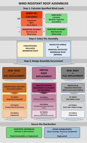
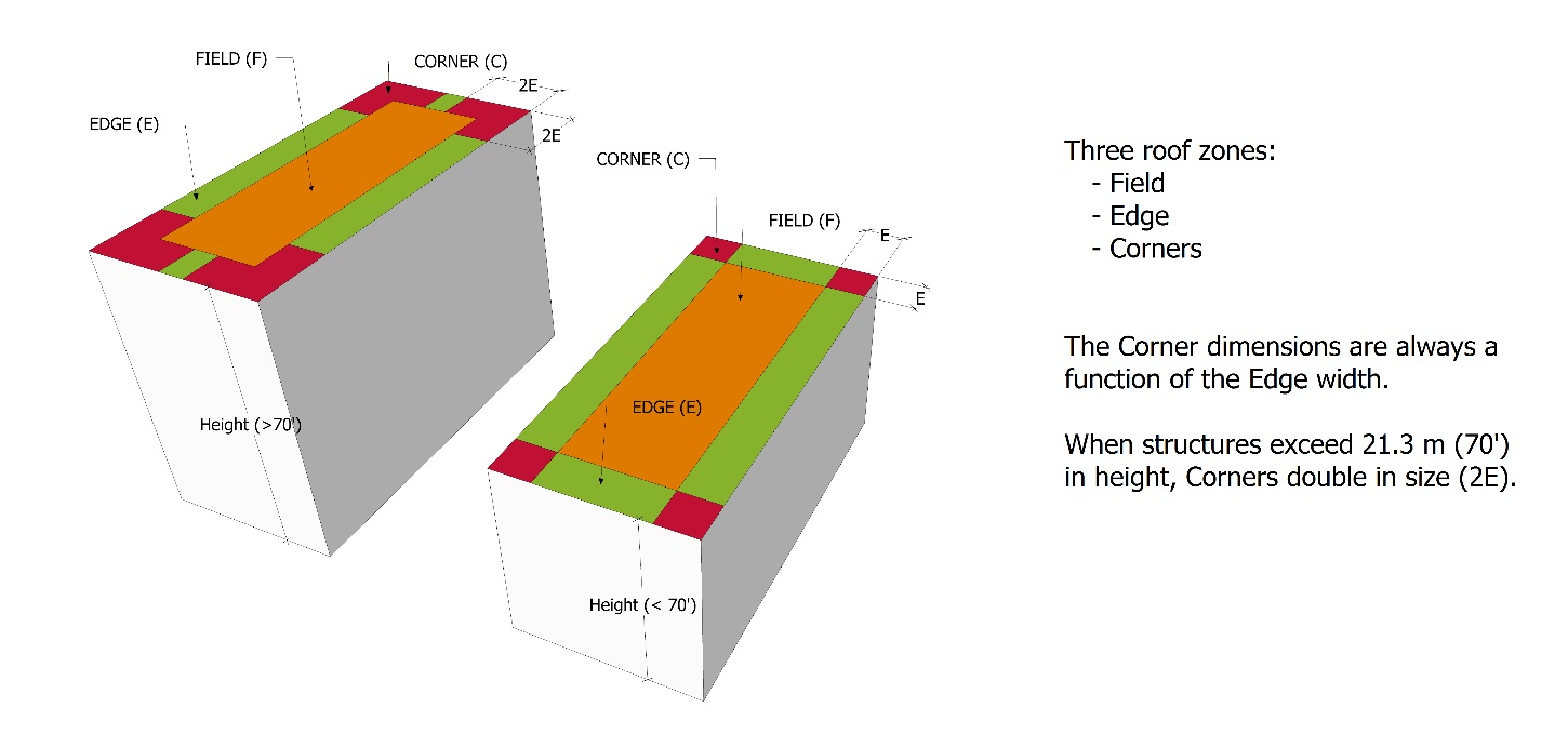
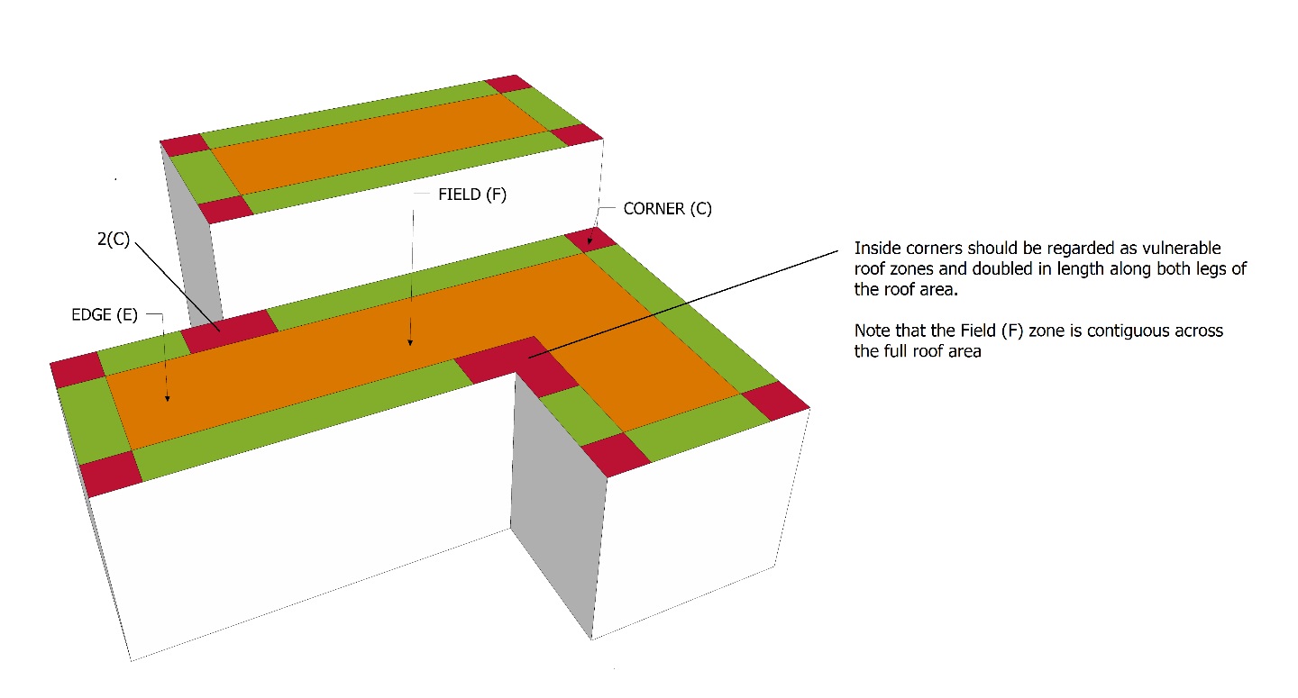
See Figure 3.3 for an illustration of this process.
See also 1.4.2 Replacement Roofing, 3.3.3 Partial Roof Replacements and Part 14 THE ROOF as a PLATFORM.

1.4.2 Roofs with Ballast or Overburdens
NOTE: the reader must consult the Design and Application requirements in 12.1 Protected and Modified Protected Membrane Roof Systems, together with requirements in Part 14 THE ROOF as a PLATFORM (with respect to Vegetated Roof Systems).
- When vegetation and its growing media is intended as either ballast or overburden on any membrane roof assembly, the Design Authority must, in addition to calculating the Specified Wind Loads for the roof assembly, determine the Specified Wind Loads for the Vegetated Roof Systems (VRS), and the dimensions of the roof zones, using the WIND-VRA online calculator tool or, in the alternative, another method that is its equal or superior. Note that this online resource applies only to buildings described on the Wind-RCI website as "low rise" and of moderate height (limited to 20 m or 65 feet) with a roof Waterproofing System. Designing appropriate securement of a VRS on roofs taller than 20 m (65') or with slopes greater than 2:12 must be undertaken by a licensed design professional using current wind engineering practices, and must be acceptable to the Authority Having Jurisdiction (AHJ). Securement methods and details of a VRS, regardless of building height and roof slope, are the responsibility of the Design Authority.
- VRSs that are not modular, and VRSs on buildings that do not conform to the parameter of the Wind-VRA calculator, must be engineered to resist Specified Wind Loads.
- Ballasted loose-laid membrane roof systems, and systems designed as PMRAs or MPMRAs that utilize gravel ballast, must be designed for adequate securement by
- calculating the Specified Wind Loads for the roof assembly.
- selecting the appropriate ballast using
- the RGC ballast guide (see 3.3.2 Ballasted Roof Systems, and 12.1 Protected and Modified Protected Membrane Roof Systems).
- the Dupont Tech Solutions 508.2 Ballast Design Guide for PMR Systems.
- a custom-engineered system.
- When pavers are selected as ballast for a Protected or Modified Protected Membrane Roof System, the Design Authority is responsible for determining the support and placement of pavers to resist wind uplift.
- Modified Protected Membrane Roof Systems must be designed for wind resistance following the requirements for Modified Protected Membrane Roof Systems and Conventionally Insulated Systems.
- The Design Authority is responsible for determining the proper securement of any overburden intended for placement on top of the roof platform. For design, material and installation standards pertaining to roofs as platforms, refer in this Manual to Part 14 The ROOF as a PLATFORM.
2 Materials
2.1 Material Substitutions in Tested Assemblies
Tested Assembly values (Dynamic Uplift Resistance) are predicated on a specific combination (system) of materials. Each material in the system possesses unique "cohesive properties" (internal strength and integrity) and is linked to the adjacent material in a particular way that may depend on a material’s unique "adhesive properties".
The substitution of material components in a Tested Assembly is not contemplated by CSA-A123.21, but Annex F (a non-mandatory part of the CSA Standard, included at the back of the Standard document for information only) includes three decision processes for MARS, PARS and AARS assemblies, to guide the Design Authority when a substitution is desirable or necessary (ref. A123.21 Standard test method for the dynamic wind uplift resistance of membrane-roofing systems, Annex F (informative) Component swap flow diagrams). Using Annex F as a basis for guidance, the following standards and guiding principles apply for the purpose of issuing a RoofStar Guarantee:
- When a manufacturer's Tested Assembly incorporates materials (and listed alternates) that are not part of the RoofStar Guarantee Program, the Design Authority must identify appropriate substitutions for those materials from the list of RoofStar-accepted Materials and consult the manufacturer concerning compatibility with the Tested Assembly.
- All material substitutions, regardless of the reason for the substitution, must be supported in writing by a registered professional qualified to perform the work in Part 4 of the Code (ref. Article 2.2.1.2 Structural Design; British Columbia Building Code, Division C, Part 2 Administrative Provisions, Section 2.2 Administration).
- Any material substitution should be limited to one (1) material component from the Tested Assembly, but the substitution of more than one material component is permissible provided the substitution complies with the other requirements in this subsection.
- Any material substitution should be made in keeping with the decision process flows for MARS, PARS and AARS assemblies published in CSA Standard A123.21 Standard test method for the dynamic wind uplift resistance of membrane-roofing systems (latest edition), Annex F.
- Because of its nature, a roof Assembly with Proven Past Performance does not qualify for material substitution.
2.2 Gravel Ballast
- Gravel ballast used to secure a Protected Membrane Roof Assembly (or Modified PMRA) assembly must be clean, washed, round or crushed stone, falling within the following gradations:
- 35 mm (1 ½") - 100 % Passing
- 25 mm (1") 70 - 100 % Passing
- 20 mm (¾") 5 - 20 % Passing
- 12.7 mm (½") 0 - 6 % Passing
- 5 mm (3/16") 0 - 2 % Passing
Any variance to the above must be accepted in writing by the owner or the owner's representative, and submitted to the RoofStar Guarantee Program as part of the Guarantee record.
2.3 Fasteners and Adhesives
The following minimum standards apply to any roof system, regardless of requirements published elsewhere.
- Fasteners and adhesives must be capable of securing the roof system components for Specified Wind Loads.
- The Design Authority should specify the correct type of fastener, keeping in mind
- pull-out strength.
- corrosion resistance (contributing factors to fastener corrosion may include dissimilar metal contact, excessive building humidity, corrosive chemicals within components of the roof system, or corrosive elements provided within the building envelope etc.).
- Unless otherwise listed in the system components of a Tested Assembly, self-drilling screws with recessed heads must be used in combination with plates as follows:
Table 3.1 Minimum Fastener and Plate Requirements Material Fastener
SizePlate Deck overlays #12 73 mm (2-7/8”) Hexagonal, 76 mm (3”) Round or Square Insulation #12 73 mm (2-7/8”) Hexagonal, 76 mm (3”) Round or Square Insulation Overlays #12 73 mm (2-7/8”) Hexagonal, 76 mm (3”) Round or Square Membranes #14 Proprietary - Adhesives listed in a selected Tested Assembly must be used to secure applicable layers within the roof system. Adhesives may be substituted only with products listed in the Tested Assembly report.
- In the absence of a Tested Assembly, or for adhered and partially adhered Assemblies with Proven Past Performance, adhesives must be acceptable to the manufacturers of the roof assembly components.
- Bitumen used as a hot-applied adhesive must be Type 3 or SEBS.
3 Application
(NOTE: this Section is critical for both the Design Authority and the Contractor)
A properly secured roof assembly is the product of three essential steps:
Step 1: Calculate the Specified Wind Loads for the roof. Step 2: Select the type of Roof Assembly representative of the roof (conventionally insulated, or a Protected/Modified Protected Membrane Roof System).
Step 3: Design the securement system using available options, depending upon the type of assembly.
This section breaks down the RoofStar Guarantee Standards according to these three fundamental steps. The Standards published in this section are the minimum requirements, regardless of fastener or adhesive requirements in a Tested Assembly, an Assembly with Proven Past Performance, or any other assembly designed by other methodologies.
3.1 Step 1: Calculate Specified Wind Loads
The information in this section may assist the Design Authority in better understanding the complexities of calculating Specified Wind Loads, how wind affects a roof and each of its zones, and how to properly apply fastener or adhesive configurations for each zone and its respective Specified Wind Loads.
Specified Wind Loads are forces exerted by wind which, in the case of a membrane roof system, both push and lift the roof system or its components. Often, the upward or uplift forces are expressed as a negative value (negative pressure), but these are influenced by many variables including, without limitation, wind speed, building height, roof slope, wall openings, roof overhangs and ground roughness.
Specified Wind Loads for membrane roof Waterproofing Systems should be calculated using the available onlineWind-RCI online wind calculator or, in the alternative, another method that is its equal or superior (click here for a sample report). When the Wind-RCI calculator is not suitable (as, for example, when a building exceeds 150 feet in height), the Design Authority must refer to the British Columbia Building Code, Division B, Parts 4 and Part 5 for further guidance.
The report generated by the Wind-RCI calculator will specify the wind loads for the Corners, the Edge ("perimeter") and the Field. These zone loads must be applied in Step 3 when determining the method of roof system securement.
3.1.1 Non-conforming Buildings
When a building’s dimensions are "non-conforming" and exceed the parameters of the Wind-RCI calculator, the following standards apply:
- The Design Authority remains responsible for the proper design of a membrane roof Waterproofing System, regardless of its method of securement. Refer to the British Columbia Building Code, Div. B, Parts 4 and Part 5 for further guidance.
- Roof systems for non-conforming buildings must be engineered for proper securement to withstand Specified Wind Loads.
- Non-conforming building roof systems must incorporate RoofStar-accepted materials.
3.2 Step 2: Select the Type of Roof Assembly
Methods for securing the roof depend, in part, on the type of roof. Conventionally Insulated Systems that support any type of overburden should be treated like an uncovered roof, and secured accordingly (see below for options available to secure a Conventionally Insulated System). When a Vegetated Roof System is specified, it is subject to different securement methods, based on its own Specified Wind Loads.
Protected Membrane Roof Systems are secured with ballast. Guidance for these is provided below in 3.3.3.2 Ballasted Roof Systems.
Follow the path in Step 3 that fits with your roof system design.
3.3 Step 3: Design Roof Assembly Securement
The following Articles provide guidance for each of the following roof assemblies:
- Conventionally Insulated Systems
- Ballasted systems
- Roofs supporting an overburden
- Partially replaced roofs
3.3.1 Conventionally Insulated Roof Assemblies
Whether the Conventionally Insulated System is covered or uncovered, it must be secured using one of three methods. These are presented below as a progression from simplicity to complexity, and from low cost (for the Design Authority) to high cost.
If the intent of the Design Authority is to replace only a part of the existing roof system, see 2.7.2 for guidance and options. See also 3.3.3.4 below.
3.3.1.1 Tested Assemblies
Tested Assemblies are material components that have been selected by the membrane manufacturer, installed on a specific deck type, secured using one of three methods (securement system), and tested by an independent certified laboratory to determine the limits of the assembly’s ability to resist negative wind pressure (loads), or ‘wind uplift’. Each of the three methods is expressed with an acronym:
- MARS, or Mechanically Attached Roof Systems – these systems are held in place only with mechanical fasteners that are installed at the membrane layer.
- PARS, or Partially Adhered Roof Systems – both mechanical fasteners and adhesives are used as a hybrid method of securement; the membrane is always adhered, using an applied adhesive or heat-welding.
- AARS, or Adhesive Applied Roof Systems – these are membrane roofs secured only with adhesives or heat-welded components.
Only Tested Assemblies that have been tested by qualified facilities wholly independent of roof system manufacturers will be regarded by the RoofStar Guarantee Program as legitimate. Click here for a list of qualified testing agencies.
To find a Tested Assembly, follow any of the links shown above.
- The Design Authority is strongly encouraged to specify the application of a Tested Assembly, for any design of a new or fully replaced membrane (waterproofing system) roof.
- The Design Authority must use only the test observation readings that have been adjusted for the Safety Factor.
- Tested Assembly observation readings, reduced by the Safety Factor, must equal or exceed the highest Specified Wind Loads for the roof. This is called the Dynamic Uplift Resistance (DUR).
- When a Tested Assembly report indicates only one system of securement, that system shall be applied to all roof zones.
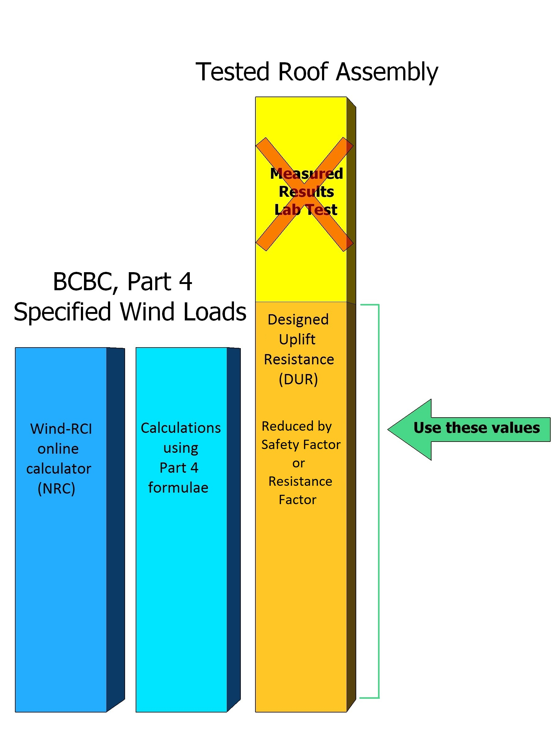
|
3.3.1.2 Roof Assemblies with Proven Past Performance
- A roof Assembly with Proven Past Performance is a Conventionally Insulated System installed on a specific supporting deck that utilizes materials acceptable for the RoofStar Guarantee Program, and which has demonstrated a proven track record of wind uplift resistance
- for at least as long as the expected life of the new roof system.
- for buildings, and in conditions, that are reasonably representative of the project the roof system will be specified for.
- Roof assemblies with Proven Past Performance
- are an acceptable alternative to a Tested Assembly when
- a Tested Assembly cannot be used.
- material components in a Tested Assembly are not accepted by the RoofStar Guarantee Program, and the Tested Assembly offers no suitable alternates.
- a Tested Assembly is not available because
- a material or system has not been tested.
- the Specified Wind Loads exceed the capacity of an available or suitable Tested Assembly.
- may be used for partial roof replacement.
- are an acceptable alternative to a Tested Assembly when
- Assemblies with Proven Past Performance must be
- designed to exceed the Specified Wind Loads for the roof.
- supported with a signed letter of assurance, issued by the Design Authority or the manufacturer of the Assembly with Proven Past Performance, that it will perform as required.
- Approvals issued by FM Global or another underwriter, for roof systems capable of resisting the Specified Wind Load of the Project, may be given consideration by the RoofStar Guarantee Program, but must be delivered to the Guarantor for review and written acceptance, along with a letter of assurance from the Design Authority or the manufacturer.
3.3.1.3 Engineered Designs
When, for various reasons, a system of securement cannot be designed using either a Tested Assembly or an Assembly with Proven Past Performance, the Design Authority must have the securement system designed by a qualified engineer following the requirements in 2.2.1.2 Structural Design; The British Columbia Building Code, Division C, Part 2, Section 2.2 Administration'.
3.3.2 Ballasted Roof Systems
NOTE: the reader must consult the Design and Application requirements for 12.1 Protected and Modified Protected Membrane Roof Systems, and for Part 14 THE ROOF as a PLATFORM (with respect to Vegetated Roof Systems).
- Roof systems secured with gravel ballast, pavers or both must be designed to resist Specified Wind Loads, regardless of any overburden the design may call for. To facilitate resistance to Specified Wind Loads,
- a filter fabric is required beneath gravel or paver ballast.
- a protection layer is required beneath crushed ballast.
- gravel ballast for a Protected Membrane Roof System must conform to
- the following minimum requirements, subject to the calculations for wind uplift resistance:
Table 3.2 RGC Ballast Guide XPS Insulation
ThicknessStone Ballast Required Weight Ballast Depth
(approximate)Up to 50 mm (2") 60 Kg/M2 (12 lb./sf) 40 mm (1 ¾") 75 mm (3") 8r Kg/M2 (17 lb./sf) 60 mm (2 ¼") 100 mm (4") 108 Kg/M2 (22 lb./sf) 75 mm (3") 125 mm (5") 132 Kg/M2 (27 lb./sf) 90 mm (3 ½") 150 mm (6") 156 Kg/M2 (32 lb./sf) 105 mm (4 ¼") 175 mm (7") 180 Kg/M2 (37 lb./sf) 125 mm (5") 200 mm (8") 204 Kg/M2 (42 lb./sf) 140 mm (5 ½")
- the appropriate design derived from Dupont Tech Solutions 508.2 Ballast Design Guide for PMR Systems.
- the following minimum requirements, subject to the calculations for wind uplift resistance:
- On roofs specified to utilize gravel ballast, no fewer than two parallel rows of pavers should be considered for Corner and Edge zones, to prevent or reduce wind scouring of the gravel. Pavers should be secured together when specified by the Dupont Ballast Design Guide.
- Loose-laid membranes held in place with gravel ballast must be secured with gravel ballast having sufficient size and weight to resist wind uplift, but shall in any event meet the following minimum requirements:
- Coverage: 60 kg/sq. m (12 lb/ft2).
- Ballast size: nominal ¾" to 1½" (19.0 mm to 38.1 mm) diameter stone meeting ASTM D 448 size #4 using ASTM C-136.
- See also 9.3.4 Loose-laid Ballasted Membranes.
3.3.3 Roofs Supporting an Overburden
- Any supported overburden must be installed in keeping with the designed securement methods and systems specified by the Design Authority, and must equal or exceed the Specified Wind Loads for the roof.
- Vegetated Roof Systems (VRSs) constructed in modules must be secured according to the methods specified by the Design Authority.
3.3.4 Partial Roof Replacement
- When only a portion of an existing roof system is specified for replacement, the new materials must be secured to resist wind Specified Wind Loads. See also 1.4.2 Replacement Roofing.
- Mechanical fastening is the most reliable method for securing new materials installed over an existing roof assembly. When mechanical fastening is not practicable, the system of securement must conform to one of the following options:
- A custom-engineered design.
- A system design with Proven Past Performance (accompanied by a letter of assurance; see the requirements under 3.3.3.1.2 Roof Assemblies with Proven Past Performance).
3.3.4.1 Mechanically Fastened Materials
- When mechanical fastening is specified by the Design Authority as the securement method, the minimum number and pattern of fasteners mandated by the RoofStar Guarantee Standards published below prevail unless exceeded by another reliable method.
- Multiple layers of insulation that are mechanically fastened must be secured together, as if they are a single layer.
- Mechanical fasteners must penetrate
- through the bottom surface of
- steel decks at least 20 mm (3/4") – fasteners should penetrate the top flutes only.
- plywood sheathing by at least 19 mm (3/4").
- into solid dimensional lumber or concrete by at least 25 mm (1").
See Figure 3.5.Figure 3.5 (Click to expand) 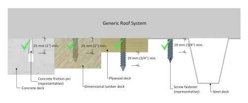
These Standards may be exceeded by the fastener manufacturer’s published requirements. - through the bottom surface of
- When mechanically attached membranes are installed together with new insulation, the insulation assembly (with or without an insulation overlay) must be held in place independently from the membrane, with no fewer than four (4) fasteners per panel.
- Table 3.3 shows the minimum required number of fasteners, unless otherwise specified by a Tested Assembly, an Assembly with Proven Past Performance, or a custom-engineered assembly. Also see the required patterns, displayed below the table:
- Fasteners must be installed no more than 150 mm (6”) from panel corners, measured from each edge of the panel.
- Fasteners used to secure boards from curling, or to secure boards at slope transitions, shall be in addition to the minimum number of fasteners and plates required by the patterns shown in Table 3.4.

Table 3.3 RGC Mechanical Fastening (minimum requirements) Material Dimensions Roof Zone Field Perimeter Corner 1200mm x 2400mm (4’ x 8’) Deck Overlay supporting mechanically attached materials 4 4 4 Insulation or Insulation Overlay supporting mechanically attached materials 4 4 4 Insulation 8 12 15 Insulation Overlays 8 12 15
1200mm x 1800mm (4’ x 6’) Insulation 6 8 12
1200mm x 1200mm (4’ x 4’) Insulation 5 6 8
900mm x 100mm (3’ x 4’) Insulation 4 6 7
600mm x 2400mm (2’ x 8’) Insulation 5 6 8
600mm x 1200mm (2’ x 4’) Insulation 4 4 5
Table 3.4 RGC Fastener pattern requirements for full-sized panels (Click on drawing to expand) 1200mm x 2400mm (4’ x 8’) Field Perimeter Corner 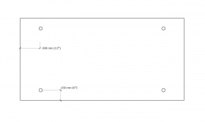 4 Fasteners 4 Fasteners 4 Fasteners
Field Perimeter Corner 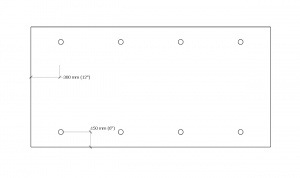 8 Fasteners
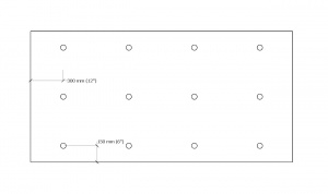 12 Fasteners
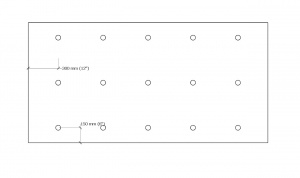 15 Fasteners


1200mm x 1200mm (4’ x 4’) Field Perimeter Corner 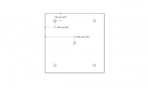 5 Fasteners
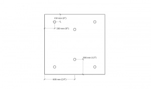 6 Fasteners
 8 Fasteners
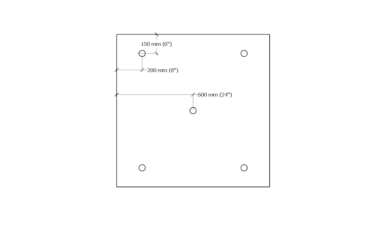
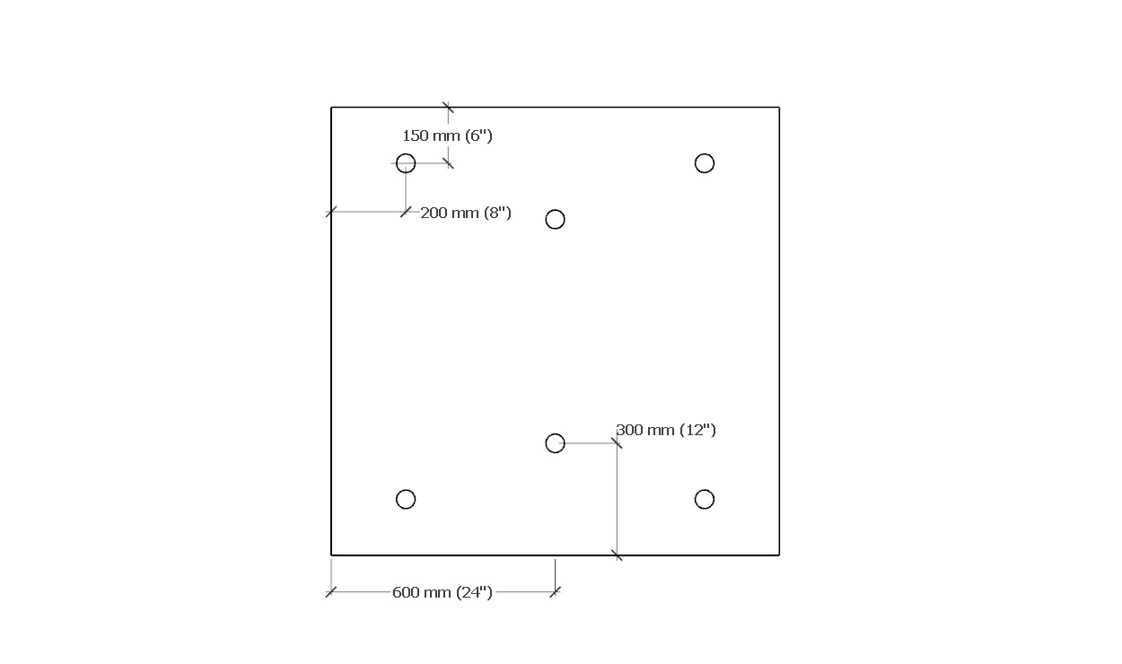
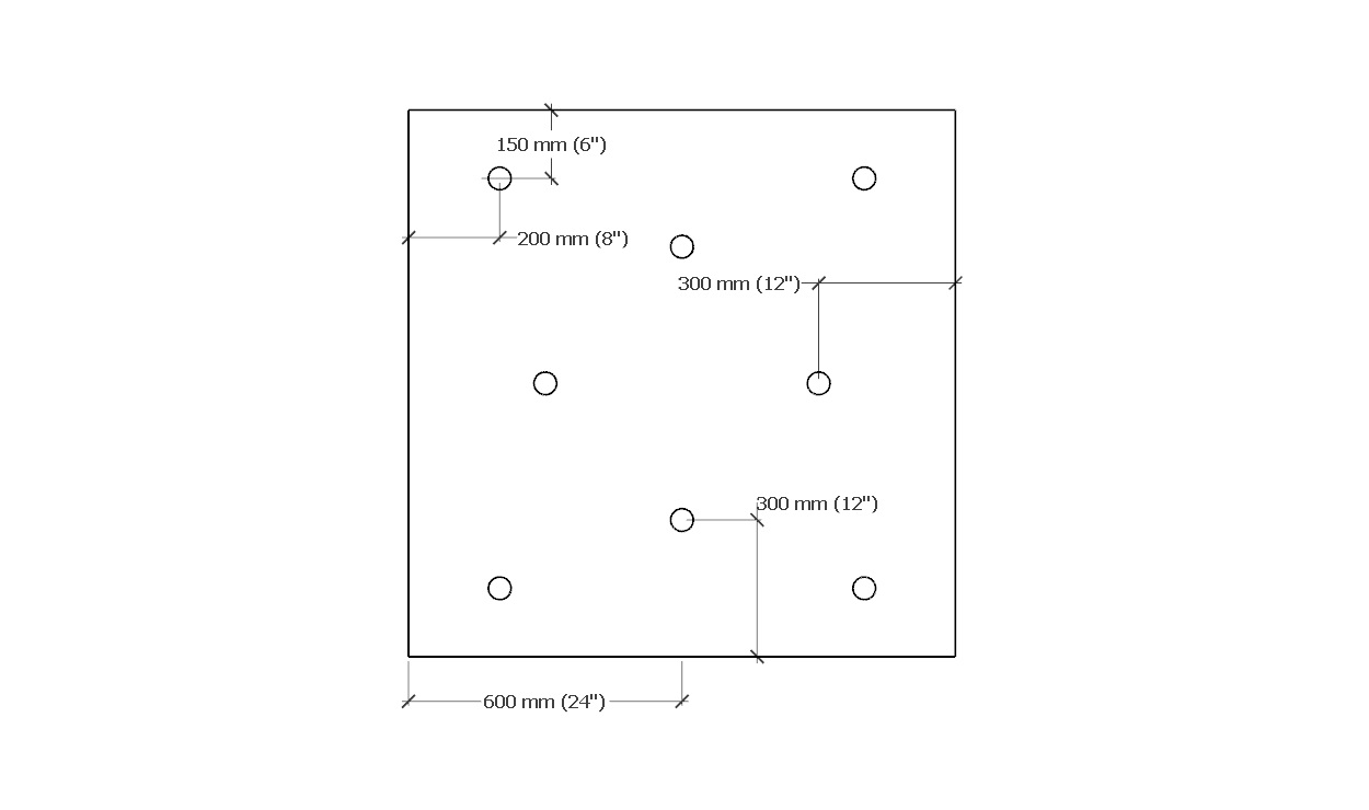
Table 3.5 RGC Fastener pattern requirements for partial panels (Click on drawing to expand) 1200mm x 1800mm (4’ x 6’) Field Perimeter Corner  6 Fasteners
 8 Fasteners
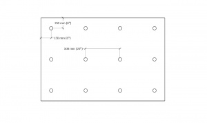 12 Fasteners
900mm x 1200mm (3’ x 4’) Field Perimeter Corner 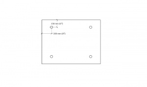 4 Fasteners
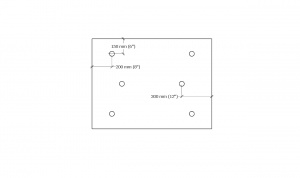 6 Fasteners
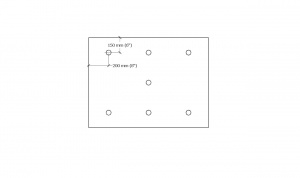 7 Fasteners
600mm x 2400mm (2’ x 8’) Field Perimeter Corner 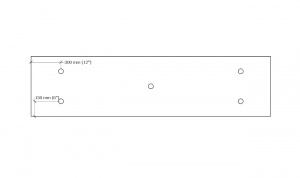 5 Fasteners
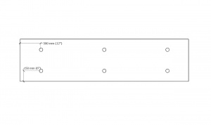 6 Fasteners
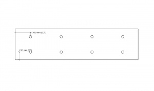 8 Fasteners
600mm x 1200mm (2’ x 4’) Field Perimeter Corner 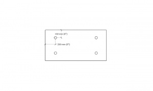 4 Fasteners 4 Fasteners
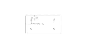 5 Fasteners
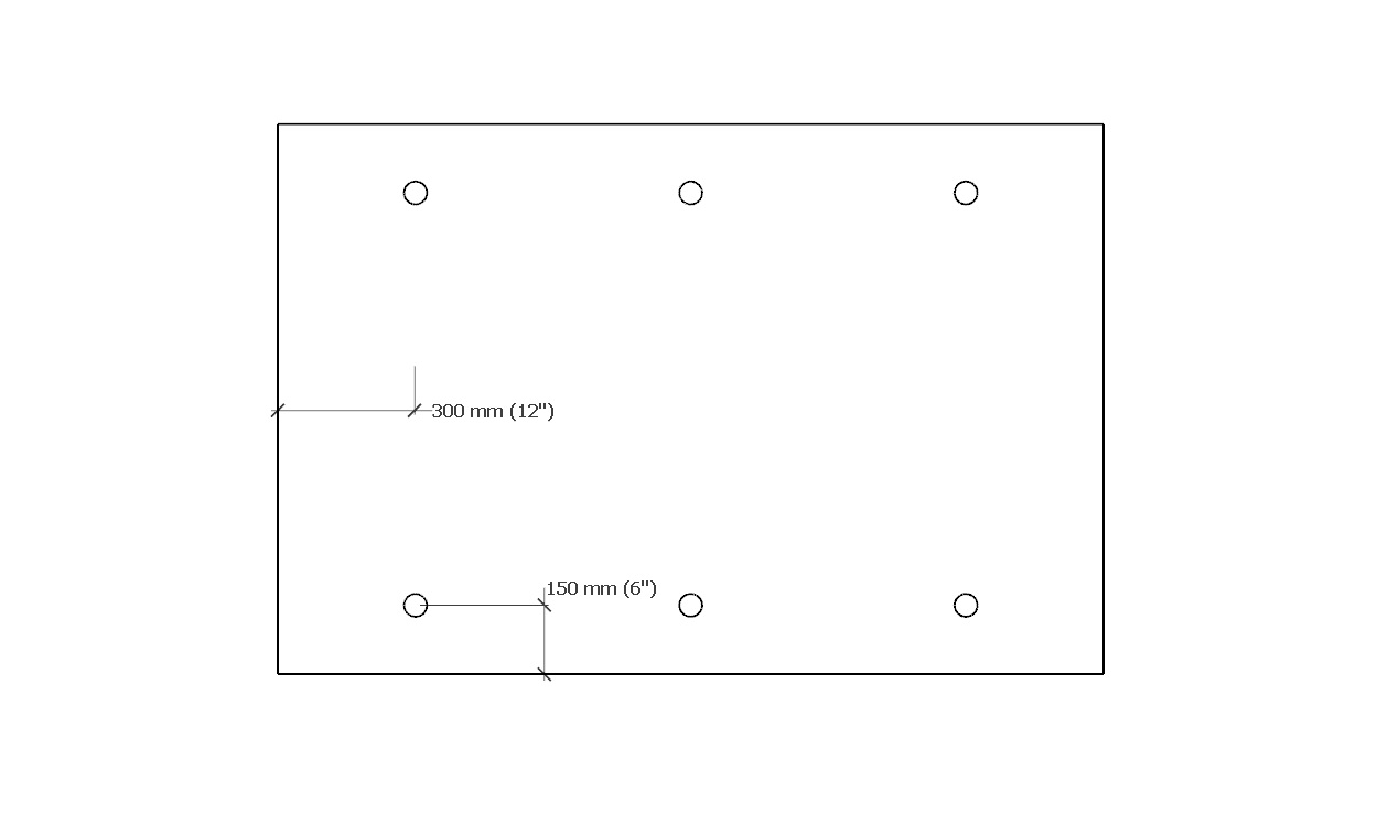


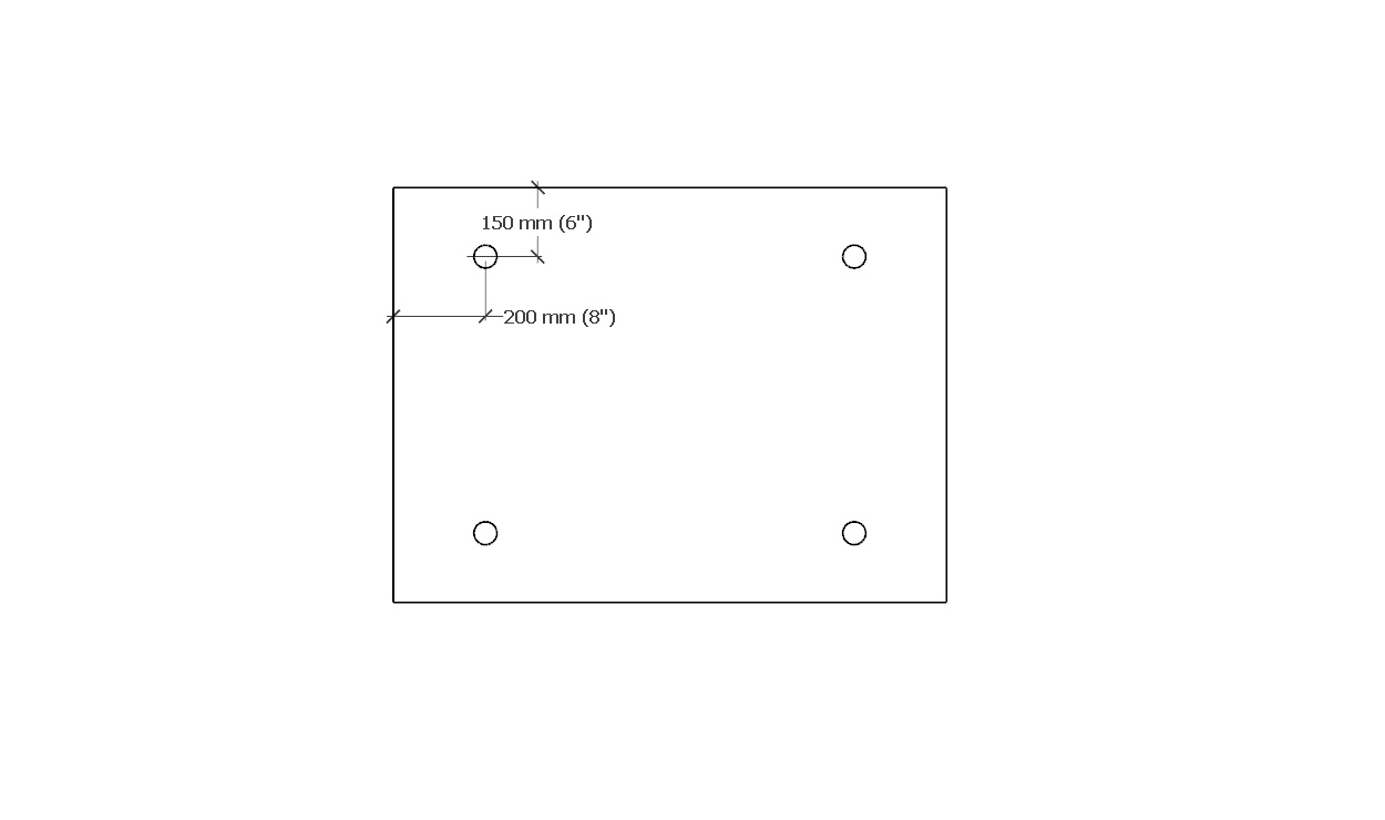
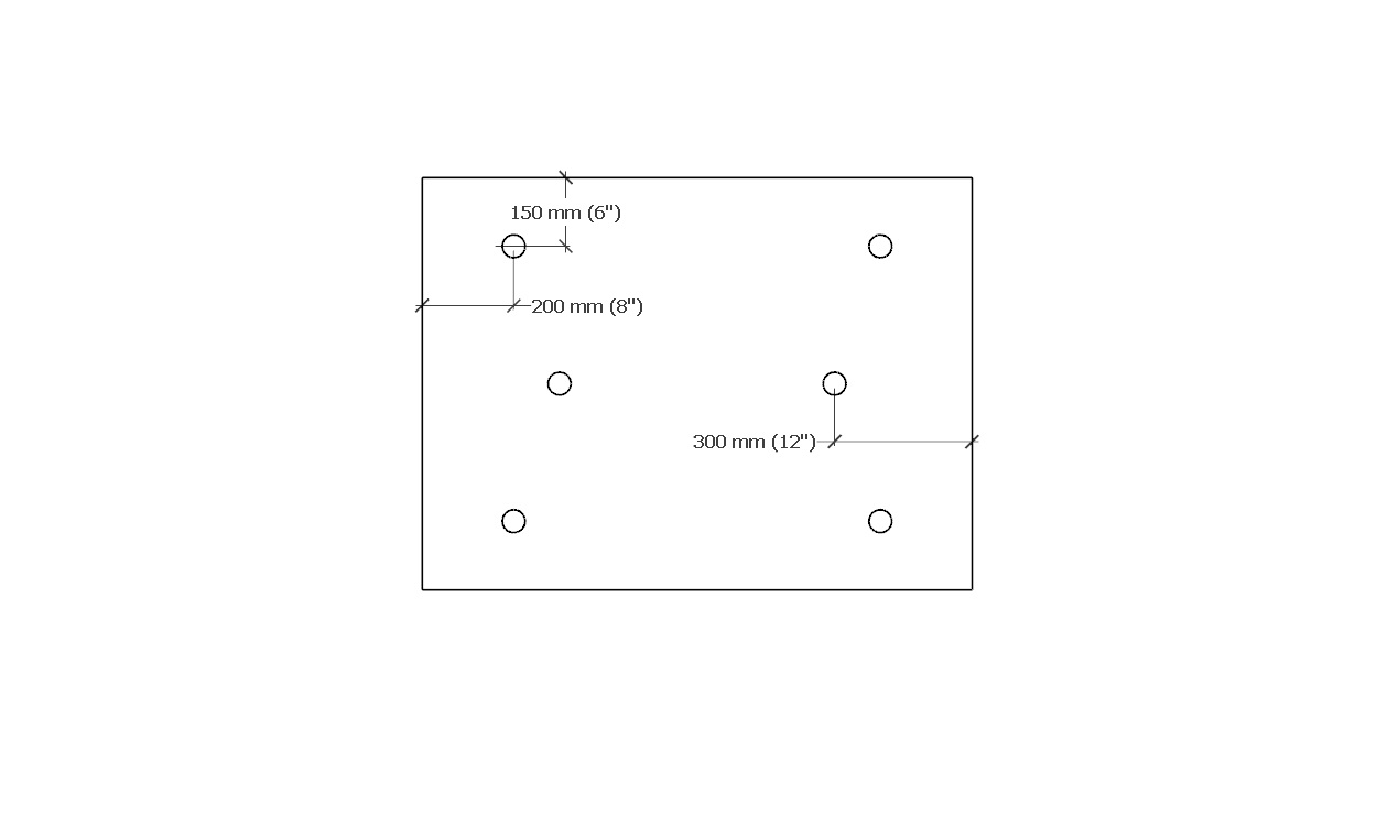


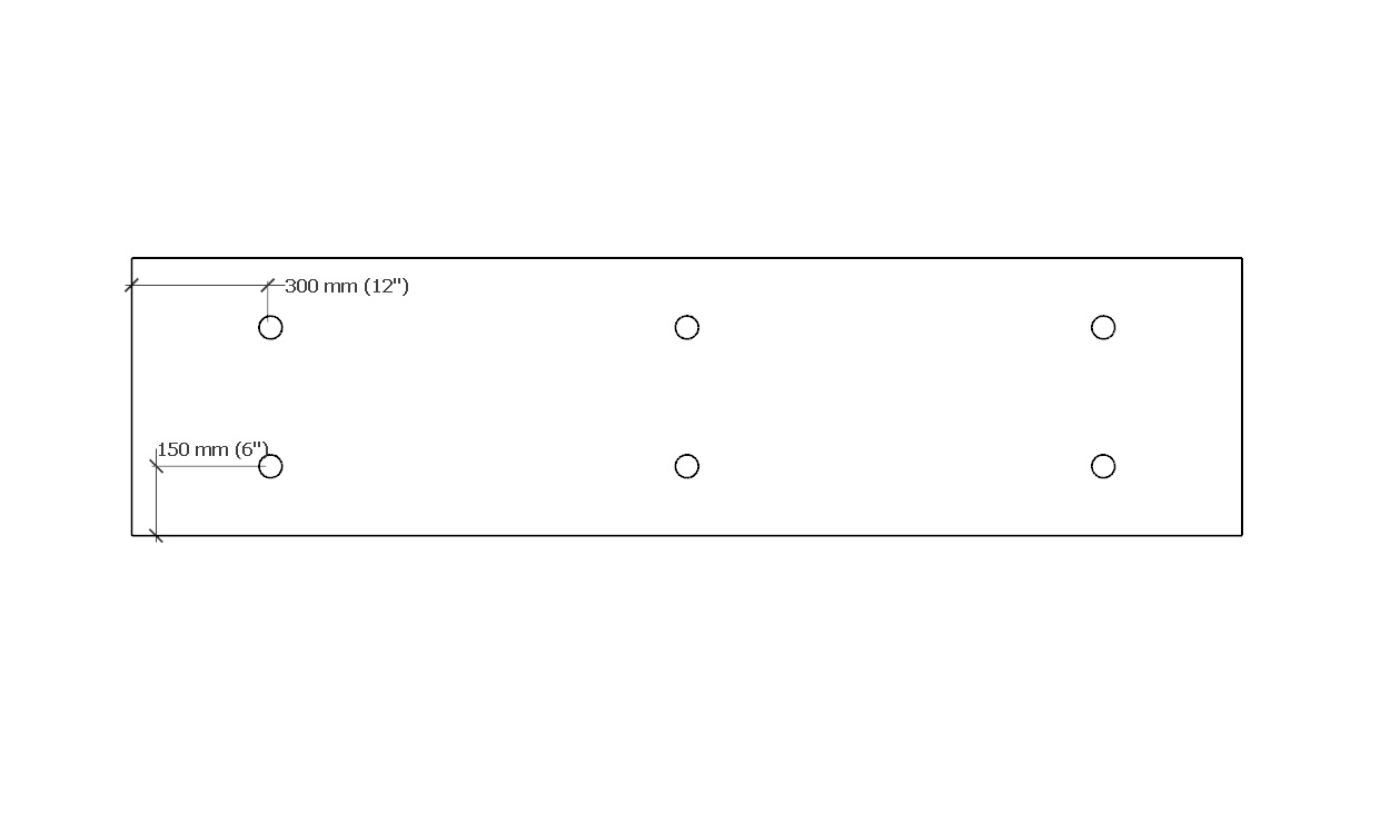


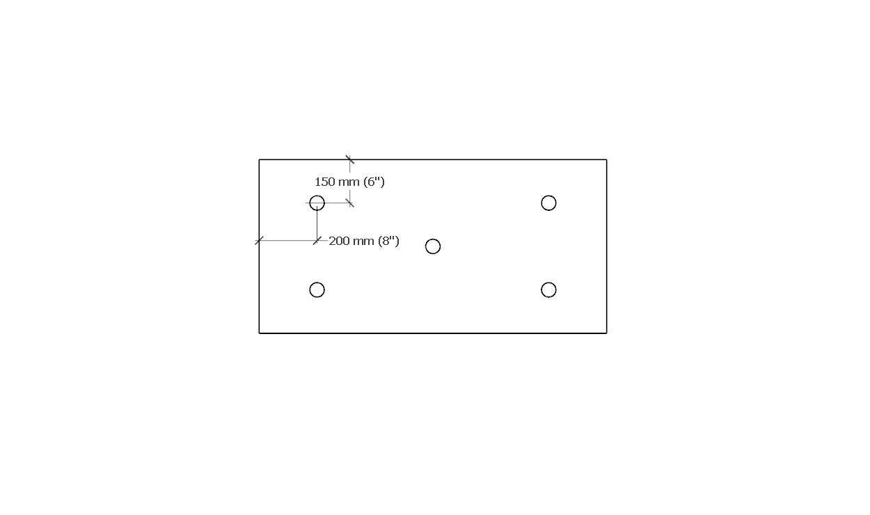
- NOTE: Fastener locations are for optimum uplift resistance. Fasteners may be located within 50 mm (2") of position shown in diagrams in any direction.
3.3.4.2 Adhesive Applied Materials
- Adhesives may be used to secure new roofing materials to an existing roof system, provided the specific application procedures and methods are engineered by or for the Design Authority.
- Notwithstanding the above, the minimum requirements set out in 7.3.2.4 apply.