
Difference between revisions of "Securing the Roof Assembly"
Difference between revisions of "Securing the Roof Assembly"
| Line 69: | Line 69: | ||
<li>{{hilite |Compliance with this Part or the Code does not guarantee that a roof will not succumb to forces exerted by wind, and therefore neither the '''''Guarantor''''' nor the ''Contractor'' will accept any responsibility for damage to, or failure of, a roof system caused by wind; too many variables beyond the control of this Standard affect the wind resistance performance of a ''roof system'', including (without limitation)|| 2021-October-30 }} | <li>{{hilite |Compliance with this Part or the Code does not guarantee that a roof will not succumb to forces exerted by wind, and therefore neither the '''''Guarantor''''' nor the ''Contractor'' will accept any responsibility for damage to, or failure of, a roof system caused by wind; too many variables beyond the control of this Standard affect the wind resistance performance of a ''roof system'', including (without limitation)|| 2021-October-30 }} | ||
<ol> | <ol> | ||
| − | <li>{{hilite | the continuity or discontinuity of air and vapour control layers of the entire building enclosure|| 2021-October-30 }}, | + | <li>{{hilite | the ''continuity'' or discontinuity of air and vapour ''control layers'' of the entire building enclosure|| 2021-October-30 }}, |
<li>{{hilite | openings in the building (windows and doors, which are often occupant-controlled and not static)|| 2021-October-30 }}, and | <li>{{hilite | openings in the building (windows and doors, which are often occupant-controlled and not static)|| 2021-October-30 }}, and | ||
| − | <li>{{hilite | wind strength, which may exceed the codified numeric wind speed values used to calculate wind resistance for the roof system (Ref. "British Columbia Building Code", Division B, [https:// | + | <li>{{hilite | wind strength, which may exceed the codified numeric wind speed values used to calculate wind resistance for the ''roof system'' || 2021-October-30 }} (Ref. "British Columbia Building Code 2024", Division B, [https://www2.gov.bc.ca/assets/gov/farming-natural-resources-and-industry/construction-industry/building-codes-and-standards/revisions-and-mo/bcbc_2024.pdf#page=762 Appendix C, "Table C-1"]). |
</li></ol> | </li></ol> | ||
</li></ol> | </li></ol> | ||
| − | ====3.1.1.4. Definitions==== | + | ====3.1.1.4. {{strike| Definitions || 2024-October-23 }}{{hilite | Defined Terms || 2025-October-25 }}==== |
<ol> | <ol> | ||
| Line 81: | Line 81: | ||
<ol> | <ol> | ||
<li>''CSA Standard'' means the CSA-A123.21, "Standard test method for the dynamic wind uplift resistance of membrane-roofing systems" (latest edition). | <li>''CSA Standard'' means the CSA-A123.21, "Standard test method for the dynamic wind uplift resistance of membrane-roofing systems" (latest edition). | ||
| − | <li>''Registered Professional'' has the same meaning as that used in the "British Columbia Building Code", Division C, [https:// | + | <li>{{hilite | ''CSA VRA Standard'' means the CSA-A123.24, “Standard test method for wind resistance of vegetated roof assembly” || 2025-October-25 }}. |
| − | <li>''Specified Wind Load'' means the calculated force of wind exerted on the roof of a specific building, according to the requirements in the "British Columbia Building Code", Division B, Part 4, [https:// | + | <li>''Registered Professional'' has the same meaning as that used in the "British Columbia Building Code 2024", Division C, [https://www2.gov.bc.ca/assets/gov/farming-natural-resources-and-industry/construction-industry/building-codes-and-standards/revisions-and-mo/bcbc_2024.pdf#page=836 Article 2.2.1.2., "Structural Design"]. |
| + | <li>''Specified Wind Load'' means the calculated force of wind exerted on the roof of a specific building, according to the requirements in the "British Columbia Building Code 2024", Division B, Part 4, [https://www2.gov.bc.ca/assets/gov/farming-natural-resources-and-industry/construction-industry/building-codes-and-standards/revisions-and-mo/bcbc_2024.pdf#page=496 Section 4.1., "Structural Loads and Procedures"]. | ||
<li>{{hilite | ''System of securement'' means a specific pattern of mechanical fasteners or adhesives, including specific materials or brands, size, and spacing. || 2023-June-16 }} | <li>{{hilite | ''System of securement'' means a specific pattern of mechanical fasteners or adhesives, including specific materials or brands, size, and spacing. || 2023-June-16 }} | ||
</li></ol> | </li></ol> | ||
| Line 88: | Line 89: | ||
===3.1.2. Guarantee Term Requirements=== | ===3.1.2. Guarantee Term Requirements=== | ||
| − | ====3.1.2.1. RoofStar 5-year and RoofStar 10-year Guarantee==== | + | ====3.1.2.1. RoofStar 5-year Guarantee and RoofStar 10-year Guarantee==== |
<ol> | <ol> | ||
| − | <li>To qualify for a '''''RoofStar 5-year''''' or '''''RoofStar 10-year Guarantee''''', all ''projects'' shall comply with the requirements in this Part. | + | <li>To qualify for a '''''RoofStar 5-year Guarantee''''' or '''''RoofStar 10-year Guarantee''''', all ''projects'' shall comply with the requirements in this Part. |
</li></ol> | </li></ol> | ||
| Line 97: | Line 98: | ||
<ol> | <ol> | ||
| − | <li>To qualify for a '''''RoofStar 15-year Guarantee''''', all ''projects'' shall comply with the requirements in this Part for a '''''RoofStar 5-year''''' or '''''RoofStar 10-year Guarantee''''', and shall | + | <li>To qualify for a '''''RoofStar 15-year Guarantee''''', all ''projects'' shall comply with the requirements in this Part for a '''''RoofStar 5-year Guarantee''''' or '''''RoofStar 10-year Guarantee''''', and shall |
<ol> | <ol> | ||
| − | <li>{{hilite |comply with the higher securement requirements when enhanced ''roof system'' securement is required by the membrane manufacturer, to meet their system warranty requirements ("enhanced securement" may exceed the securement stated or specified in a ''Tested Assembly'', an ''Assembly with Proven Past Performance'', or a custom-engineered design; see also [[#1.1.2.1. RoofStar 5-Year and RoofStar 10-year Guarantee | Article 1.1.2.1., | + | <li>{{hilite |comply with the higher securement requirements when enhanced ''roof system'' securement is required by the membrane manufacturer, to meet their system warranty requirements ("enhanced securement" may exceed the securement stated or specified in a ''Tested Assembly'', an ''Assembly with Proven Past Performance'', or a custom-engineered design; see also [[#1.1.2.1. RoofStar 5-Year Guarantee and RoofStar 10-year Guarantee | Article 1.1.2.1., "RoofStar 15-Year Guarantee"]], for further general requirements|| 2020-October-22 }}). |
| + | </li></ol> | ||
| + | </li></ol> | ||
| + | |||
| + | ===={{hilite | 3.1.2.3. RoofStar Vegetated Roof Guarantee || 2025-October-25 }}==== | ||
| + | |||
| + | <ol> | ||
| + | <li>To qualify for a '''''RoofStar Vegetated Roof Guarantee''''', the supporting ''roof assembly'' shall | ||
| + | <ol> | ||
| + | <li>comply with the requirements in this Part for a '''''RoofStar 5-year Guarantee''''', '''''RoofStar 10-year Guarantee''''', or a '''''RoofStar 15-year Guarantee''''', | ||
| + | <li>be acceptable to the manufacturer as support for a ''vegetated roof system'', and | ||
| + | <li>comply with the related requirements in the [https://rpm.rcabc.org/index.php?title=VRA_Standard “RGC Standard for Vegetated Roofs”]. | ||
</li></ol> | </li></ol> | ||
</li></ol> | </li></ol> | ||
| Line 114: | Line 126: | ||
<ol> | <ol> | ||
| − | <li>A ''registered professional'' "skilled in the work concerned" must perform or validate the calculation of ''Specified Wind Loads'' (See the "British Columbia Building Code", Division C, Part 2, | + | <li>A ''registered professional'' "skilled in the work concerned" must perform or validate the calculation of ''Specified Wind Loads'' (See the "British Columbia Building Code 2024", Division C, Part 2, [https://www2.gov.bc.ca/assets/gov/farming-natural-resources-and-industry/construction-industry/building-codes-and-standards/revisions-and-mo/bcbc_2024.pdf#page=836 Article 2.2.1.2., "Structural Design"]), using |
<ol> | <ol> | ||
<li>the [https://nrc.canada.ca/en/research-development/products-services/software-applications/wind-load-calculators-roof-cladding-vegetated-roof-assembly "Wind Uplift Resistance Calculator"] (formerly "Wind-RCI"), or | <li>the [https://nrc.canada.ca/en/research-development/products-services/software-applications/wind-load-calculators-roof-cladding-vegetated-roof-assembly "Wind Uplift Resistance Calculator"] (formerly "Wind-RCI"), or | ||
| − | <li>the formulae and procedures in the "British Columbia Building Code", Division B, Part 4, [https:// | + | <li>the formulae and procedures in the "British Columbia Building Code 2024", Division B, Part 4, [https://www2.gov.bc.ca/assets/gov/farming-natural-resources-and-industry/construction-industry/building-codes-and-standards/revisions-and-mo/bcbc_2024.pdf#page=529 Subsection 4.1.7.,"Wind Load"] (See [[Notes to SBS Standard#A-3.1.1.1. | Note A-3.1.1.1.]]). |
</li></ol> | </li></ol> | ||
| − | <li>Each roof area, at each level (elevation), shall be divided into three principal roof zones (Figure 3.1.), and the ''Design Authority'' shall be responsible for calculating the ''Specified Wind Loads'' for each zone (Ref. the "British Columbia Building Code", Division B, Part 4, [https:// | + | <li>Each roof area, at each level (elevation), shall be divided into three principal roof zones ({{hilite | '''Figure 3.1.3.2.-A''' || 2025-October-25 }}), and the ''Design Authority'' shall be responsible for calculating the ''Specified Wind Loads'' for each zone (Ref. the "British Columbia Building Code 2024", Division B, Part 4, [https://www2.gov.bc.ca/assets/gov/farming-natural-resources-and-industry/construction-industry/building-codes-and-standards/revisions-and-mo/bcbc_2024.pdf#page=535 Article 4.1.7.6., "External Pressure Coefficients for Low Buildings"]). |
<li>Roof zones are defined in this Standard as follows: | <li>Roof zones are defined in this Standard as follows: | ||
<ol> | <ol> | ||
<li>'''Field (F)''' – the interior of the roof bounded by the ''Edge'' and the ''Corners''. | <li>'''Field (F)''' – the interior of the roof bounded by the ''Edge'' and the ''Corners''. | ||
<li>'''Edge (E)''' – the perimeter zone (minus the corners), measured as either 10% of the smallest building width ("least horizontal dimension"), or 40% of the building height, whichever is less. Notwithstanding the requirements in the "British Columbia Building Code", the ''Edge'' zone shall not be less than 2.0 m (7'). | <li>'''Edge (E)''' – the perimeter zone (minus the corners), measured as either 10% of the smallest building width ("least horizontal dimension"), or 40% of the building height, whichever is less. Notwithstanding the requirements in the "British Columbia Building Code", the ''Edge'' zone shall not be less than 2.0 m (7'). | ||
| − | <li>'''Corner (C)''' – part of the perimeter but not less than 2.0 m x 2.0 m (7’ x7’) in size, the ''Corner'' area is defined by the ''Edge'' in both directions at the corners. Where the roof geometry includes an inside corner, the ''corner'' zone dimensions shall be the same as those for an outside corner, applied equidistant in each direction from the inside corner (Figure 3.1.3.-A). | + | <li>'''Corner (C)''' – part of the perimeter but not less than 2.0 m x 2.0 m (7’ x7’) in size, the ''Corner'' area is defined by the ''Edge'' in both directions at the corners. Where the roof geometry includes an inside corner, the ''corner'' zone dimensions shall be the same as those for an outside corner, applied equidistant in each direction from the inside corner ({{hilite | '''Figure 3.1.3.2.-A''' || 2025-October-25 }}). |
</li></ol> | </li></ol> | ||
| − | {| | + | <br> |
| − | + | {| | |
|- | |- | ||
| − | | [[File:Figure 3.1.jpg|link= | + | |- |
| + | | colspan="1"; style="text-align:center;width:450px;" | {{hilite | '''Figure 3.1.3.2.-A Principal Roof Zones''' || 2025-October-25 }}<br>{{hilite | Forming Part of Article 3.1.3.2. || 2025-October-25 }}<br><small>(Click to expand illustration)</small> | ||
| + | |- | ||
| + | | [[File:Figure 3.1.3.2.-A (Wind Zones).jpg|link=https://rpm.rcabc.org/images/9/9a/Figure_3.1.3.2.-A_%28Wind_Zones%29.jpg | 400 px]] | ||
|} | |} | ||
<br> | <br> | ||
| − | <li>A roof area that is divided into smaller segments by means of ''control joints'' (roof dividers, i.e., a fire wall) or ''expansion joints'', shall be considered one roof area for the purpose of calculating the ''Specified Wind Loads'', unless the height of a ''control joint'' or ''expansion joint'' exceeds 1 m (39"), in which case the ''Specified Wind Loads'' for each roof segment shall be calculated separately (See Figure 3.1.3.-B). | + | <li>A roof area that is divided into smaller segments by means of ''control joints'' (roof dividers, i.e., a fire wall) or ''expansion joints'', shall be considered one roof area for the purpose of calculating the ''Specified Wind Loads'', unless the height of a ''control joint'' or ''expansion joint'' exceeds 1 m (39"), in which case the ''Specified Wind Loads'' for each roof segment shall be calculated separately (See {{hilite | '''Figure 3.1.3.2.-B''' || 2025-October-25 }}). |
| − | <li>When a building is designed with multiple roof levels (at different elevations), and the roofs are adjacent each other (having a common wall), the ''Specified Wind Loads'' for each level, and for each roof area on that level, shall be calculated separately from loads for the adjacent level, unless the elevation difference between adjacent roof levels is less than 1.524 m (5’) ( | + | <li>When a building is designed with multiple roof levels (at different elevations), and the roofs are adjacent each other (having a common wall), the ''Specified Wind Loads'' for each level, and for each roof area on that level, shall be calculated separately from loads for the adjacent level, unless the elevation difference between adjacent roof levels is less than 1.524 m (5’) (See {{hilite | '''Figure 3.1.3.2.-B''' || 2025-October-25 }}). |
| − | <li>When the shape of a single-level roof varies in width or length, the smallest width dimensions shall be used in the calculation of ''Specified Wind Loads'' (Ref. “minimum effective width” as defined in the "British Columbia Building Code", Division B, Part 4, [https:// | + | <li>When the shape of a single-level roof varies in width or length, the smallest width dimensions shall be used in the calculation of ''Specified Wind Loads'' (Ref. “minimum effective width” as defined in the "British Columbia Building Code", Division B, Part 4, [https://www2.gov.bc.ca/assets/gov/farming-natural-resources-and-industry/construction-industry/building-codes-and-standards/revisions-and-mo/bcbc_2024.pdf#page=530 Article 4.1.7.2., "Classification of Buildings"]). |
| − | {| | + | <br><br> |
| − | | | + | {| |
| + | |- | ||
| + | |- | ||
| + | | colspan="1"; style="text-align:center;width:450px;" | {{hilite | '''Figure 3.1.3.2.-B Roofs Adjacent to Each Other''' || 2025-October-25 }}<br>{{hilite | Forming Part of Article 3.1.3.2. || 2025-October-25 }}<br><small>(Click to expand illustration)</small> | ||
|- | |- | ||
| − | | | + | | [[File:Figure 3.1.3.2.-B (Wind Zones).jpg|link=https://rpm.rcabc.org/images/6/64/Figure_3.1.3.2.-B_%28Wind_Zones%29.jpg | 550 px]] |
|} | |} | ||
<br> | <br> | ||
| − | <li>When a roof area intersects the corner of a wall, the ''Edge'' zone on either side of the wall corner must be treated as a roof ''Corner'' (2 x C) (Figure 3.1.3.-B). | + | <li>When a roof area intersects the corner of a wall, the ''Edge'' zone on either side of the wall corner must be treated as a roof ''Corner'' (2 x C) ({{hilite | '''Figure 3.1.3.2.-B''' || 2025-October-25 }}). |
<li>When an existing roof system is specified for partial replacement, the ''Design Authority'' must | <li>When an existing roof system is specified for partial replacement, the ''Design Authority'' must | ||
<ol> | <ol> | ||
| Line 152: | Line 170: | ||
<li>Mansards are a ''roof system'' and are therefore subject to the requirements in this Part. | <li>Mansards are a ''roof system'' and are therefore subject to the requirements in this Part. | ||
<li>Securement of an adjoining ''water-shedding system'' shall be made in accordance with the requirements in the applicable Standard. | <li>Securement of an adjoining ''water-shedding system'' shall be made in accordance with the requirements in the applicable Standard. | ||
| − | <li>''Vegetated Roof Systems'' specified for | + | <li>{{hilite | Wind loads for a ''roof assembly'' supporting a ''vegetated roof system'' shall be determined in accordance with the requirements of the Building Code and || 2025-October-25 }} [https://rpm.rcabc.org/index.php?title=VRA_Standard#3.1.3.3. Resistance to Specified Wind Loads | Article 3.1.3.3.]] {{hilite | of the “RGC Standard for Vegetated Roofs”|| 2025-October-25 }}. |
| + | {{strike| <li>''Vegetated Roof Systems'' specified for || 2024-October-24 }} | ||
<ol> | <ol> | ||
| − | <li>buildings up to 20 m (65') in height shall be designed to resist ''Specified Wind Loads'' using the [https://nrc.canada.ca/en/research-development/products-services/software-applications/wind-load-calculators-roof-cladding-vegetated-roof-assembly "Wind Load Calculator for Vegetated Roof Assembly"] or, in the alternative, another method that is its equal or superior, and | + | {{strike| <li>buildings up to 20 m (65') in height shall be designed to resist ''Specified Wind Loads'' using the [https://nrc.canada.ca/en/research-development/products-services/software-applications/wind-load-calculators-roof-cladding-vegetated-roof-assembly "Wind Load Calculator for Vegetated Roof Assembly"] or, in the alternative, another method that is its equal or superior, and || 2024-October-24 }} |
| − | <li>buildings greater than 20 m (65') in height shall be designed to resist '' Specified Wind Loads'' using methods that are acceptable to the ''Authority Having Jurisdiction'' (AHJ). | + | {{strike| <li>buildings greater than 20 m (65') in height shall be designed to resist '' Specified Wind Loads'' using methods that are acceptable to the ''Authority Having Jurisdiction'' (AHJ). || 2024-October-24 }} |
</li></ol> | </li></ol> | ||
</li></ol> | </li></ol> | ||
| Line 164: | Line 183: | ||
<ol> | <ol> | ||
<li>The wind uplift resistance capabilities of the selected ''roof system'' must equal or exceed the ''Specified Wind Loads'' calculated for each roof zone to which the ''system'' will be applied (see [[#3.1.3.2. Calculation of Specified Wind Loads | Article 3.1.3.2.]]). | <li>The wind uplift resistance capabilities of the selected ''roof system'' must equal or exceed the ''Specified Wind Loads'' calculated for each roof zone to which the ''system'' will be applied (see [[#3.1.3.2. Calculation of Specified Wind Loads | Article 3.1.3.2.]]). | ||
| − | <li>Engineered designs to resist wind uplift may refer to the "British Columbia Building Code", Div. B, [https:// | + | <li>Engineered designs to resist wind uplift may refer to the "British Columbia Building Code", Div. B, [https://www2.gov.bc.ca/assets/gov/farming-natural-resources-and-industry/construction-industry/building-codes-and-standards/revisions-and-mo/bcbc_2024.pdf#page=764 Appendix C, "Table C-2"], which lists various types of loads, including wind loads, for specific reference locations throughout the province. |
</li></ol> | </li></ol> | ||
| Line 177: | Line 196: | ||
<li>thermal expansion and contraction of the ''roof system'' components. | <li>thermal expansion and contraction of the ''roof system'' components. | ||
</li></ol> | </li></ol> | ||
| + | <li>{{hilite | Where the roof is designed to support a ''vegetated roof system'', consideration for other loads shall conform to the requirements in|| 2025-October-25 }} [https://rpm.rcabc.org/index.php?title=VRA_Standard#2.1.4.1._Structural_Loads {{hilite |Article 2.1.4.1.|| 2025-October-25 }}] {{hilite |of the “RGC Standard for Vegetated Roofs”|| 2025-October-25 }}. | ||
</li></ol> | </li></ol> | ||
====3.1.3.5. Submittals==== | ====3.1.3.5. Submittals==== | ||
| + | |||
| + | {{strike| <ol> | ||
| + | <li>{{hilite | The '''''Guarantor''''' must receive from the ''Contractor'', prior to construction of the ''project'' and to document the ''roof system'' record || 2024-June-15 }}, | ||
| + | <ol> | ||
| + | <li>{{hilite | a Tested Assembly report supplied or endorsed by a ''manufacturer'', including documentation of the substitution of any materials identified in that test report || 2024-June-15 }}, | ||
| + | <li>{{strike| The ''Design Authority'' must submit documentation || 2023-June-15 }} {{hilite | a letter || 2024-June-15 }} in support of an {{hilite | ''Assembly with Proven Past Performance'' || 2025-October-25 }}{{strike| "System with Proven Past Performance" || 2024-October-24 }}, as required in [[#3.1.4.3. Specifying an Assembly with Proven Past Performance | Article 3.1.4.3.(2)]], {{hilite | or || 2024-June-15 }} | ||
| + | <li>{{hilite | a custom-engineered ''system'' for securing the ''roof assembly'' || 2024-June-15 }}. | ||
| + | </li></ol> | ||
| + | </li></ol> || 2024-October-25 }} | ||
<ol> | <ol> | ||
| − | <li> | + | <li>{{hilite | Refer to the requirements in || 2025-October-25 }} [[#1.3.2.4. Contractor Submittals | {{hilite | Article 1.3.2.4. || 2025-October-25 }}]] |
</li></ol> | </li></ol> | ||
| Line 210: | Line 239: | ||
<ol> | <ol> | ||
| − | <li>Only roof assemblies that have been tested by qualified facilities wholly independent of ''roof system'' manufacturers, using CSA-A123.21, "Standard test method for the dynamic wind uplift resistance of membrane-roofing systems" (latest edition), will be considered valid ''Tested Assemblies'', for the purposes of this Standard (See [http://rpm.rcabc.org/index.php/CSA_A123.21_Qualified_Test_Facilities | + | <li>Only roof assemblies that have been tested by qualified facilities wholly independent of ''roof system'' manufacturers, using CSA-A123.21, "Standard test method for the dynamic wind uplift resistance of membrane-roofing systems" (latest edition), will be considered valid ''Tested Assemblies'', for the purposes of this Standard (See [http://rpm.rcabc.org/index.php/CSA_A123.21_Qualified_Test_Facilities here] for a list of qualified testing agencies). |
<li><span class="recommended">The ''Design Authority'' is strongly encouraged to specify the application of a ''Tested Assembly'', for any design of a new or fully replaced membrane waterproofing ''roof system''</span>. | <li><span class="recommended">The ''Design Authority'' is strongly encouraged to specify the application of a ''Tested Assembly'', for any design of a new or fully replaced membrane waterproofing ''roof system''</span>. | ||
| − | <li>The ''Design Authority'' must use only the test observation readings that have been adjusted for the "Safety Factor" (CSA-A123.21, prior to the 2019 edition) or the "Resistance Factor" (CSA-A123.21, 2019 and newer), which must equal or exceed the highest ''Specified Wind Loads'' for the roof (this adjusted value is called the ''Dynamic Uplift Resistance'', or DUR. See Figure 3.1.4.-A). | + | <li>The ''Design Authority'' must use only the test observation readings that have been adjusted for the "Safety Factor" (CSA-A123.21, prior to the 2019 edition) or the "Resistance Factor" (CSA-A123.21, 2019 and newer), which must equal or exceed the highest ''Specified Wind Loads'' for the roof (this adjusted value is called the ''Dynamic Uplift Resistance'', or DUR. See {{hilite | '''Figure 3.1.4.2.-A''' || 2025-October-25 }}). |
| − | <li>When a ''Tested Assembly'' report indicates only one system of securement, that system shall be applied to all roof zones; alternatively, zone-specific securement requirements may be extrapolated by a ''Registered Professional'' "skilled in the work concerned", using ANSI-SPRI WD-1, "Wind Design Standard Practice for Roofing Assemblies" (see the "British Columbia Building Code", Division B, Part 5, Notes to Part 5, [https:// | + | <li>When a ''Tested Assembly'' report indicates only one system of securement, that system shall be applied to all roof zones; alternatively, zone-specific securement requirements may be extrapolated by a ''Registered Professional'' "skilled in the work concerned", using ANSI-SPRI WD-1, "Wind Design Standard Practice for Roofing Assemblies" (see the "British Columbia Building Code", Division B, Part 5, Notes to Part 5, [https://www2.gov.bc.ca/assets/gov/farming-natural-resources-and-industry/construction-industry/building-codes-and-standards/revisions-and-mo/bcbc_2024.pdf#page=674 A-5.2.2.2.(4)]). |
| − | + | </li></ol> | |
| − | {| | + | <br> |
| − | | | + | ::{| |
| + | |- | ||
| + | |- | ||
| + | | colspan="1"; style="text-align:center;width:450px;" | {{hilite | '''Figure 3.1.4.2.-A Dynamic Uplift Resistance''' || 2025-October-25 }}<br>{{hilite | Forming Part of Article 3.1.4.2. || 2025-October-25 }}<br><small>(Click to expand illustration)</small> | ||
|- | |- | ||
| [[File:Figure 3.4.jpg|link=http://rpm.rcabc.org/images/d/d8/Figure_3.4.jpg | 250 px]] | | [[File:Figure 3.4.jpg|link=http://rpm.rcabc.org/images/d/d8/Figure_3.4.jpg | 250 px]] | ||
|} | |} | ||
| − | |||
====3.1.4.3. Specifying an Assembly with Proven Past Performance==== | ====3.1.4.3. Specifying an Assembly with Proven Past Performance==== | ||
| − | + | (See the "British Columbia Building Code", Division B, Part 5, Notes to Part 5, [https://www2.gov.bc.ca/assets/gov/farming-natural-resources-and-industry/construction-industry/building-codes-and-standards/revisions-and-mo/bcbc_2024.pdf#page=671 A-5.1.4.1.(5)] for an expanded explanation of the tests for "proven past performance") | |
| − | (See the "British Columbia Building Code", Division B, Part 5, Notes to Part 5, [https:// | ||
<ol> | <ol> | ||
| − | <li>A new ''conventionally insulated'' ''roof assembly'' (the '' | + | <li>A new ''conventionally insulated'' ''roof assembly'' (the new ''roof assembly'') may be designed using a model ''roof assembly'' as a reference (the roof ''Assembly with Proven Past Performance''), but only when |
<ol> | <ol> | ||
<li>a ''Tested Assembly'' cannot be used, | <li>a ''Tested Assembly'' cannot be used, | ||
<li>the material components identified in a ''Tested Assembly'' are not accepted by the '''''RoofStar Guarantee Program''''', and the test report offers no RoofStar-accepted alternates, | <li>the material components identified in a ''Tested Assembly'' are not accepted by the '''''RoofStar Guarantee Program''''', and the test report offers no RoofStar-accepted alternates, | ||
<li>a ''Tested Assembly'' is not available because a material or ''system'' has not been tested, or because the ''Specified Wind Loads'' exceed the capacity of an available or suitable ''Tested Assembly'', | <li>a ''Tested Assembly'' is not available because a material or ''system'' has not been tested, or because the ''Specified Wind Loads'' exceed the capacity of an available or suitable ''Tested Assembly'', | ||
| − | <li>the '' | + | <li>the model ''roof assembly'' |
<ol> | <ol> | ||
<li>is an existing ''roof assembly'' constructed on a real, existing building (the ''model building''), | <li>is an existing ''roof assembly'' constructed on a real, existing building (the ''model building''), | ||
<li>demonstrates resistance to negative wind loads that are the same as, or greater than, the ''Specified Wind Loads'' which the ''new roof assembly'' must be designed to resist, | <li>demonstrates resistance to negative wind loads that are the same as, or greater than, the ''Specified Wind Loads'' which the ''new roof assembly'' must be designed to resist, | ||
<li>has a history of performance equal to or longer than the expected service life of the ''new roof assembly'', and | <li>has a history of performance equal to or longer than the expected service life of the ''new roof assembly'', and | ||
| − | <li>is designed with only RoofStar-accepted materials that possess properties "identical or superior to those of the...assembly used as a reference" (Ref. the "British Columbia Building Code", Division B | + | <li>is designed with only RoofStar-accepted materials that possess properties "identical or superior to those of the...assembly used as a reference" (Ref. the "British Columbia Building Code", Division B, [https://www2.gov.bc.ca/assets/gov/farming-natural-resources-and-industry/construction-industry/building-codes-and-standards/revisions-and-mo/bcbc_2024.pdf#page=670 Notes to Part 5, Environmental Separation]), |
</li></ol> | </li></ol> | ||
| − | <li>the | + | <li>the model building |
<ol> | <ol> | ||
<li>is similar in dimensions, exposure, openings, and importance to the building that will support the ''new roof assembly'', and | <li>is similar in dimensions, exposure, openings, and importance to the building that will support the ''new roof assembly'', and | ||
| − | <li>is situated in conditions representative of the building that will support the '' | + | <li>is situated in conditions representative of the building that will support the new ''roof assembly'' (the term "representative" refers to conditions that include, without limitation, dynamic loads caused by proximity to other structures because of funneling or building harmonics). |
</li></ol> | </li></ol> | ||
</li></ol> | </li></ol> | ||
| − | <li>To qualify for a '''''RoofStar Guarantee''''', a '' | + | <li>To qualify for a '''''RoofStar Guarantee''''', a new ''roof assembly'' patterned after {{hilite | a model ''roof assembly'' and the design using a model ''roof assembly'' || 2025-October-25 }}{{strike| an ''Assembly with Proven Past Performance'' || 2024-October-25 }} must be supported with a letter of assurance provided to the '''''Guarantor''''' by the ''Design Authority'', or by the manufacturer of the ''Assembly with Proven Past Performance'', signed by the Principal or a person having the authority of the Principal, stating that the new ''roof assembly'' will resist the ''Specified Wind Loads'' calculated for the new ''roof assembly''. |
| − | <li>A ''new roof assembly'' patterned after an ''Assembly with Proven Past Performance'' may be used for partial roof replacement. | + | <li>A ''new roof assembly'' patterned after {{hilite | a model ''roof assembly'' || 2025-October-25 }}{{strike| an ''Assembly with Proven Past Performance'' || 2024-October-25 }} may be used for partial roof replacement. |
<li>Published approvals issued by an insurer or underwriter, or roof assembly designs warranted or guaranteed by anyone other than the '''''Guarantor''''', do not satisfy the requirements for a roof ''Assembly with Proven Past Performance''. | <li>Published approvals issued by an insurer or underwriter, or roof assembly designs warranted or guaranteed by anyone other than the '''''Guarantor''''', do not satisfy the requirements for a roof ''Assembly with Proven Past Performance''. | ||
</li></ol> | </li></ol> | ||
| Line 253: | Line 283: | ||
<ol> | <ol> | ||
| − | <li>When, for various reasons, a system of securement cannot be designed using either a ''Tested Assembly'' or an ''Assembly with Proven Past Performance'', the securement system must be designed by a ''Registered Professional'' "skilled in the work concerned" (See the "British Columbia Building Code", Division C, Part 2, [ | + | <li>When, for various reasons, a system of securement cannot be designed using either a ''Tested Assembly'' or an ''Assembly with Proven Past Performance'', the securement system must be designed by a ''Registered Professional'' "skilled in the work concerned" (See the "British Columbia Building Code", Division C, Part 2, [https://www2.gov.bc.ca/assets/gov/farming-natural-resources-and-industry/construction-industry/building-codes-and-standards/revisions-and-mo/bcbc_2024.pdf#page=836 Article 2.2.1.2., "Structural Design"]). |
</li></ol> | </li></ol> | ||
| Line 263: | Line 293: | ||
<ol> | <ol> | ||
<li>All uninsulated ''roof systems'' must be designed to resist displacement by ''Specified Wind Loads'', using the options articulated in [[#3.1.4.1. Securement Against Specified Wind Loads | Article 3.1.4.1.]] | <li>All uninsulated ''roof systems'' must be designed to resist displacement by ''Specified Wind Loads'', using the options articulated in [[#3.1.4.1. Securement Against Specified Wind Loads | Article 3.1.4.1.]] | ||
| + | <li>{{hilite | Where air intrusion into the ''roof assembly'' could compromise its securement, every ''roof assembly'' design must provide guidance for the installation of ''control layers'', particularly where ''control layers'' intersect roof drains, penetrations, or assemblies adjacent to the roof (i.e., walls) (Ref. || 2024-June-15 }} [[#Part_6_-_Air_and_Vapour_Controls | Part 6, "Air and Vapour Controls"]]). | ||
</li></ol> | </li></ol> | ||
| Line 269: | Line 300: | ||
====3.1.6.1. Securement of Ballasted Roof Systems==== | ====3.1.6.1. Securement of Ballasted Roof Systems==== | ||
| − | (Also see [[#9.1.6. Protected Roof Systems | Subsection 9.1.6., "Protected Roof Systems"]]) | + | (See [[Notes to SBS Standard#A-3.1.6.1. | {{hilite | Note A-3.1.6.1. || 2024-October-20 }}]]. Also see [[#9.1.6. Protected Roof Systems | Subsection 9.1.6., "Protected Roof Systems"]]) |
<ol> | <ol> | ||
| − | <li>''Roof systems'' secured with gravel ballast, pavers, or a combination of each, must be designed to resist displacement by ''Specified Wind Loads'', regardless of any ''overburden'' the design may call for. | + | <li>''Roof systems'' secured with {{hilite | stone (gravel) || 2025-October-25 }} ballast, pavers, or a combination of each, must be designed to resist displacement by ''Specified Wind Loads'', regardless of any ''overburden'' the design may call for. |
| − | <li>The securement of all ''roof systems'' held in place by ballast must be designed by a ''registered professional'' "skilled in the work concerned" ("British Columbia Building Code", Division C, [https:// | + | <li>The securement of all ''roof systems'' held in place by ballast must be designed by a ''registered professional'' "skilled in the work concerned" ("British Columbia Building Code", Division C, [https://www2.gov.bc.ca/assets/gov/farming-natural-resources-and-industry/construction-industry/building-codes-and-standards/revisions-and-mo/bcbc_2024.pdf#page=836 Section 2.2., "Administration"]), and ballast rates shall conform to |
<ol> | <ol> | ||
| − | <li>the minimum requirements in Table 3.1. (Ref. [[#3.3.5.1. Ballasted Systems | Article 3.3.5.1., "Ballasted Systems"]], and [[#9.3.6. Protected Roof Systems | Subsection 9.3.6., "Protected Roof Systems"]]), or | + | <li>the minimum requirements in {{hilite | '''Table 3.1.6.1.''' || 2025-October-25 }} (Ref. [[#3.3.5.1. Ballasted Systems | Article 3.3.5.1., "Ballasted Systems"]], and [[#9.3.6. Protected Roof Systems | Subsection 9.3.6., "Protected Roof Systems"]]), or |
<li>extrapolated values using ANSI-SPRI RP-4 (latest edition), "Wind Design Standard for Ballasted Single-ply Roofing Systems". | <li>extrapolated values using ANSI-SPRI RP-4 (latest edition), "Wind Design Standard for Ballasted Single-ply Roofing Systems". | ||
</li></ol> | </li></ol> | ||
| − | <li>{{hilite | | + | <li>{{hilite | {{hilite | Stone ballast || 2025-October-25 }} size for all ballasted ''roof systems'' shall conform to ASTM D7655/D7655M-12, "Standard Classification for Size of Aggregate Used as Ballast for Membrane Roof Systems". || 2023-June-16 }} |
<li>To facilitate resistance to ''Specified Wind Loads'', | <li>To facilitate resistance to ''Specified Wind Loads'', | ||
<ol> | <ol> | ||
| Line 284: | Line 315: | ||
<li>a protection layer is required beneath crushed ballast. | <li>a protection layer is required beneath crushed ballast. | ||
</li></ol> | </li></ol> | ||
| − | <li><span class="recommended">On roofs specified to utilize gravel ballast, no fewer than two parallel rows of pavers should be considered for ''Corner'' and ''Edge'' zones, to prevent or reduce wind scouring of the gravel</span>. | + | <li><span class="recommended">On roofs specified to utilize {{hilite | stone || 2025-October-25 }}{{strike| gravel || 2024-October-25 }} ballast, no fewer than two parallel rows of pavers should be considered for ''Corner'' and ''Edge'' zones, to prevent or reduce wind scouring of the gravel</span>. |
<li>When pavers are selected as ballast for a ''roof system'', the ''Design Authority'' must determine the support and placement of pavers to resist displacement by ''Specified Wind Loads''. | <li>When pavers are selected as ballast for a ''roof system'', the ''Design Authority'' must determine the support and placement of pavers to resist displacement by ''Specified Wind Loads''. | ||
| + | <li>{{hilite | ''Vegetated roof systems'' designed as ballast for a ''protected membrane roof assembly'' shall be designed in accordance with the requirements in|| 2025-October-25 }} [https://rpm.rcabc.org/index.php?title=VRA_Standard#PART_3 {{hilite |Part 3|| 2025-October-25 }}] {{hilite |of the “RGC Standard for Vegetated Roofs”|| 2025-October-25 }}. | ||
</li></ol> | </li></ol> | ||
| − | {| class="wikitable" style="text-align: left; margin-left: 20pt; margin-right: auto; border: none;" | + | <br> |
| − | + | :::{| | |
| + | |- | ||
| + | |- | ||
| + | | colspan="1"; style="text-align:center;width:450px;" | {{hilite | '''Table 3.1.6.1.<br>Minimum Requirements for Stone Ballast''' || 2025-October-25 }}<br>{{hilite | Forming Part of Article 3.1.6.1. || 2025-October-25 }}<br><small>{{hilite | (Note: these requirements apply only where no other guidance for stone ballast<br>has been provied by the ''Design Authority'') || 2025-October-25 }}</small> | ||
| + | |- | ||
| + | |} | ||
| + | :{| class="wikitable" style="text-align: left; margin-left: 20pt; margin-right: auto; border: none;" | ||
|- | |- | ||
| − | ! XPS Insulation<br>Thickness !! Stone Ballast Required Weight !! Ballast Depth<br>(approximate) | + | ! XPS Insulation<br>Thickness !! Stone Ballast Required Weight !! Minimum Ballast Depth<br>(approximate)<sup>†</sup> |
|- | |- | ||
| Up to 50.8 mm (2") || 60 Kg/M<sup>2</sup> (12 lb./sf) || 44.45 mm (1-3/4") | | Up to 50.8 mm (2") || 60 Kg/M<sup>2</sup> (12 lb./sf) || 44.45 mm (1-3/4") | ||
| Line 307: | Line 345: | ||
|- | |- | ||
|} | |} | ||
| + | ::<small><sup>†</sup> These minimum requirements should be noted by the ''registered professional'' <br>designing the ballast system.</small> | ||
====3.1.6.2. Securement of Modified Protected Roof Systems==== | ====3.1.6.2. Securement of Modified Protected Roof Systems==== | ||
| Line 325: | Line 364: | ||
<ol> | <ol> | ||
<li>Partial roof replacements must be designed to secure the ''roof system'' against displacement by ''Specified Wind Loads'', in keeping with the requirements in [[#3.1.3.2. Calculation of Specified Wind Loads | Article 3.1.3.2.]] (See also [[#3.3.6.2. Partial Roof Replacement | Article 3.3.6.2.]]). | <li>Partial roof replacements must be designed to secure the ''roof system'' against displacement by ''Specified Wind Loads'', in keeping with the requirements in [[#3.1.3.2. Calculation of Specified Wind Loads | Article 3.1.3.2.]] (See also [[#3.3.6.2. Partial Roof Replacement | Article 3.3.6.2.]]). | ||
| − | <li>When specifying securement for a partial roof replacement, the securement system must be designed and specified by the ''Design Authority'' (See also [[#1.1.4. Replacement and Alterations | Subsection 1.1.4., "Replacement and Alterations"]]); <span class="recommended">nevertheless, mechanical fastening, when practicable, is the recommended method for securing new materials to an existing ''roof system''</span> (See [[Notes to SBS Standard#A-3. | + | <li>When specifying securement for a partial roof replacement, the securement system must be designed and specified by the ''Design Authority'' (See also [[#1.1.4. Replacement and Alterations | Subsection 1.1.4., "Replacement and Alterations"]]); <span class="recommended">nevertheless, mechanical fastening, when practicable, is the recommended method for securing new materials to an existing ''roof system''</span> (See [[Notes to SBS Standard#A-3.1.7.2. | Note A-3.1.7.2.]]). |
</li></ol> | </li></ol> | ||
| Line 337: | Line 376: | ||
<ol> | <ol> | ||
<li>{{hilite | written approval from the technical manager of the ''manufacturer'' stating that the substituting material will not reduce the capabilities of the ''Tested Assembly''|| 2021-October-30 }}, or | <li>{{hilite | written approval from the technical manager of the ''manufacturer'' stating that the substituting material will not reduce the capabilities of the ''Tested Assembly''|| 2021-October-30 }}, or | ||
| − | <li>{{hilite | a letter of support issued by a registered professional qualified to perform the work in Part 4 of the Building Code (Ref. the "British Columbia Building Code", Division C, Part 2, [ | + | <li>{{hilite | a letter of support issued by a registered professional qualified to perform the work in Part 4 of the Building Code (Ref. the "British Columbia Building Code", Division C, Part 2,|| 2021-October-30 }} [https://www2.gov.bc.ca/assets/gov/farming-natural-resources-and-industry/construction-industry/building-codes-and-standards/revisions-and-mo/bcbc_2024.pdf#page=837 {{hilite |Article 2.2.1.2., "Structural Design"|| 2021-October-30 }}]). |
</li></ol> | </li></ol> | ||
<li><span class="principles">{{hilite | Any material substitution should|| 2021-October-30 }}</span> | <li><span class="principles">{{hilite | Any material substitution should|| 2021-October-30 }}</span> | ||
| Line 358: | Line 397: | ||
</li></ol> | </li></ol> | ||
<li>Fasteners must be capable of securing the ''roof system'' components to resist ''Specified Wind Loads''. | <li>Fasteners must be capable of securing the ''roof system'' components to resist ''Specified Wind Loads''. | ||
| − | <li>Unless otherwise permitted in writing by the ''manufacturer'', fasteners shall be resin-coated, self-drilling screws manufactured with recessed heads, and must be used in combination with plates, as shown in Table 3.2. | + | <li>Unless otherwise permitted in writing by the ''manufacturer'', fasteners shall be resin-coated, self-drilling screws manufactured with recessed heads, and must be used in combination with plates, as shown in {{hilite | '''Table 3.2.2.1.''' || 2025-October-25 }} |
</li></ol> | </li></ol> | ||
| + | <br> | ||
| + | ::::{| | ||
| + | |- | ||
| + | |- | ||
| + | | colspan="1"; style="text-align:center;width:450px;" | {{hilite | '''Table 3.2.2.1.<br>Minimum Fastener and Plate Requirements''' || 2025-October-25 }}<br>{{hilite | Forming Part of Article 3.2.2.1. || 2025-October-25 }}<br><small>{{hilite | (Note: these requirements apply only where no other guidance for fastener and plate types and sizes has been provided by the ''Design Authority'') || 2025-October-25 }}</small> | ||
| + | |- | ||
| + | |} | ||
{| class="wikitable" style="margin-left: 20pt; margin-right: auto;border-color:#E7E9E9;vertical-align:top;text-align:center;" | {| class="wikitable" style="margin-left: 20pt; margin-right: auto;border-color:#E7E9E9;vertical-align:top;text-align:center;" | ||
| − | |||
|- | |- | ||
! Material !! Fastener<br>Size !! Plate | ! Material !! Fastener<br>Size !! Plate | ||
| Line 384: | Line 429: | ||
<li>may be substituted only with products listed in the ''Tested Assembly'' report. | <li>may be substituted only with products listed in the ''Tested Assembly'' report. | ||
</li></ol> | </li></ol> | ||
| − | <li>In the absence of a ''Tested Assembly'', or for adhered and partially | + | <li>In the absence of a ''Tested Assembly'', or for adhered and partially adhered ''roof assemblies'' with ''Proven Past Performance'', adhesives used to secure new roofing materials must be acceptable to the ''manufacturer'' and must be demonstrably capable of resisting ''Specified Wind Loads''. |
<li>Bitumen used as a hot-applied adhesive must be Type 3 or SEBS. | <li>Bitumen used as a hot-applied adhesive must be Type 3 or SEBS. | ||
</li></ol> | </li></ol> | ||
| − | ====3.2.2.3. Gravel Ballast==== | + | ====3.2.2.3. Stone (Gravel) Ballast==== |
| − | (See also Table 3.1. in [[#3.1.6.1. Securement of Ballasted Roof Systems | Article 3.1.6.1.]]) | + | (See also {{hilite | '''Table 3.1.6.1.''' || 2025-October-25 }} in [[#3.1.6.1. Securement of Ballasted Roof Systems | Article 3.1.6.1.]]) |
<ol> | <ol> | ||
| − | <li> | + | <li>{{hilite | Stone (gravel) || 2025-October-25 }} ballast used to secure a ''roof system'' must be washed (clean) round or crushed stone and must conform to ASTM D7655/D7655M-12, "Standard Classification for Size of Aggregate Used as Ballast for Membrane Roof Systems", or to {{hilite | '''Table 3.2.2.3.''' || 2025-October-25 }} |
<li>The minimum requirements in this Article must not be reduced except by a written Variance that shall be endorsed in writing by the owner or the owner's representative, and submitted to the '''''RoofStar Guarantee Program''''' as part of the '''''Guarantee''''' record. | <li>The minimum requirements in this Article must not be reduced except by a written Variance that shall be endorsed in writing by the owner or the owner's representative, and submitted to the '''''RoofStar Guarantee Program''''' as part of the '''''Guarantee''''' record. | ||
</li></ol> | </li></ol> | ||
| − | {| class="wikitable" style="text-align: left; margin-left: 20pt; margin-right: auto; border: none;" | + | <br> |
| − | + | {| | |
| + | |- | ||
| + | |- | ||
| + | | colspan="1"; style="text-align:center;width:450px;" | {{hilite | '''Table 3.2.2.3.<br>Stone Ballast Size and Grades''' || 2025-October-25 }}<br>{{hilite | Forming Part of Article 3.2.2.3. || 2025-October-25 }} | ||
| + | |- | ||
| + | |} | ||
| + | :::{| class="wikitable" style="text-align: left; margin-left: 20pt; margin-right: auto; border: none;" | ||
|- | |- | ||
! Nominal size !! Percentage Passing | ! Nominal size !! Percentage Passing | ||
| Line 426: | Line 477: | ||
==Section 3.3. Application== | ==Section 3.3. Application== | ||
===3.3.1. Guarantee Term Requirements=== | ===3.3.1. Guarantee Term Requirements=== | ||
| − | ====3.3.1.1. RoofStar 5-year and RoofStar 10-year Guarantee==== | + | ====3.3.1.1. RoofStar 5-year Guarantee and RoofStar 10-year Guarantee==== |
<ol> | <ol> | ||
| − | <li>To qualify for a '''''RoofStar 5-year''''' or '''''RoofStar 10-year Guarantee''''', all ''projects'' shall comply with the requirements in this Part. | + | <li>To qualify for a '''''RoofStar 5-year Guarantee''''' or '''''RoofStar 10-year Guarantee''''', all ''projects'' shall comply with the requirements in this Part. |
</li></ol> | </li></ol> | ||
| Line 435: | Line 486: | ||
<ol> | <ol> | ||
| − | <li>All ''projects'' intended to qualify for a '''''RoofStar 15-year Guarantee''''' shall comply with the requirements in this Standard for a '''''RoofStar 5-year''''' or '''''RoofStar 10-year Guarantee''''', and shall | + | <li>All ''projects'' intended to qualify for a '''''RoofStar 15-year Guarantee''''' shall comply with the requirements in this Standard for a '''''RoofStar 5-year Guarantee''''' or '''''RoofStar 10-year Guarantee''''', and shall |
<ol> | <ol> | ||
| − | <li>conform to the specified design when enhanced ''roof system'' securement is required (See [[#3.1.2.1. RoofStar 5-year and RoofStar 10-year Guarantee | Article 3.1.2.1.]]). | + | <li>conform to the specified design when enhanced ''roof system'' securement is required (See [[#3.1.2.1. RoofStar 5-year Guarantee and RoofStar 10-year Guarantee | Article 3.1.2.1.]]). |
</li></ol> | </li></ol> | ||
</li></ol> | </li></ol> | ||
| Line 447: | Line 498: | ||
<li>Unless otherwise specified by a ''Tested Assembly'', a ''roof assembly'' with ''Proven Past Performance'', or a custom-engineered ''assembly'', | <li>Unless otherwise specified by a ''Tested Assembly'', a ''roof assembly'' with ''Proven Past Performance'', or a custom-engineered ''assembly'', | ||
<ol> | <ol> | ||
| − | <li>fastener patterns shall conform to | + | <li>fastener patterns shall conform to the minimum requirements published in '''Table 3.3.2.1.-B''' through '''Table 3.3.2.1.-G''', |
| − | <li>the minimum number of fasteners must conform to the requirements in Table 3. | + | <li>the minimum number of fasteners must conform to the requirements in '''Table 3.3.2.1.-A''', and |
<li>fasteners shall be installed at least 152.4 mm (6”) from panel corners, measured from each edge of the panel, but the precise placement of fasteners shall be confirmed with the ''manufacturer''. | <li>fasteners shall be installed at least 152.4 mm (6”) from panel corners, measured from each edge of the panel, but the precise placement of fasteners shall be confirmed with the ''manufacturer''. | ||
</li></ol> | </li></ol> | ||
| − | <li>Fasteners used to secure boards from curling, or to secure boards at slope transitions, shall be additional to the minimum number of fasteners and plates required by a ''Tested Assembly'', a ''roof assembly'' with ''Proven Past Performance'', a custom-engineered ''assembly'', or the patterns shown in | + | <li>Fasteners used to secure boards from curling, or to secure boards at slope transitions, shall be additional to the minimum number of fasteners and plates required by a ''Tested Assembly'', a ''roof assembly'' with ''Proven Past Performance'', a custom-engineered ''assembly'', or the patterns shown in '''Table 3.3.2.1.-B''' through '''Table 3.3.2.1.-G'''. |
<li>When mechanically attached membranes are installed together with new insulation, the ''insulation assembly'' {{hilite | (with or without an ''insulation overlay'')|| 2020-July-3 }} must be held in place independently from the membrane, with no fewer than four (4) fasteners per panel. | <li>When mechanically attached membranes are installed together with new insulation, the ''insulation assembly'' {{hilite | (with or without an ''insulation overlay'')|| 2020-July-3 }} must be held in place independently from the membrane, with no fewer than four (4) fasteners per panel. | ||
| − | <li>{{hilite | Regardless of where fasteners are used in the ''roof system'', when they penetrate and secure another material to a substrate, mechanical fasteners must conform to the requirements illustrated in {{hilite | Figure 3. | + | <li>{{hilite | Regardless of where fasteners are used in the ''roof system'', when they penetrate and secure another material to a substrate, mechanical fasteners must conform to the requirements illustrated in {{hilite | '''Figure 3.3.2.1.-A'''|| 2021-October-30 }} and shall (unless exceeded by the fastener manufacturer’s published requirements)|| 2020-July-3 }} |
<ol> | <ol> | ||
<li>{{hilite |penetrate through the bottom surface of|| 2021-October-30 }} | <li>{{hilite |penetrate through the bottom surface of|| 2021-October-30 }} | ||
| Line 462: | Line 513: | ||
<li>{{hilite |penetrate into solid dimensional lumber or concrete by at least 25.4 mm (1")|| 2021-October-30 }}. | <li>{{hilite |penetrate into solid dimensional lumber or concrete by at least 25.4 mm (1")|| 2021-October-30 }}. | ||
</li></ol> | </li></ol> | ||
| + | <li>{{hilite | Unless otherwise provided for in a ''Tested Assembly'' report, in the documentation for an ''Assembly with Proven Past Performance'', or by a ''Registered Professional'' in a custom-engineered securement system, mechanical fastening of panel materials shall conform to the minimum RGC Guarantee historical requirements in '''Table 3.3.2.1.-A''' through '''Table 3.3.2.1.-G''' || 2025-October-25 }}. | ||
</li></ol> | </li></ol> | ||
| − | :{| | + | <br> |
| − | | | + | ::::::::{| |
| + | |- | ||
| + | |- | ||
| + | | colspan="1"; style="text-align:center;width:450px;" | {{hilite | '''Figure 3.3.2.1.-A Fastener Penetration Into or Through Deck''' || 2025-October-25 }}<br>{{hilite | Forming Part of Sentence 3.3.2.1.(4). || 2025-October-25 }}<br><small>(Click to expand illustration)</small> | ||
|- | |- | ||
| [[File:Figure 3.5.jpg|link=http://rpm.rcabc.org/images/9/95/Figure_3.5.jpg| 500 px]] | | [[File:Figure 3.5.jpg|link=http://rpm.rcabc.org/images/9/95/Figure_3.5.jpg| 500 px]] | ||
|} | |} | ||
| − | {| | + | :{| |
| − | |||
|- | |- | ||
| − | |||
| − | |||
|- | |- | ||
| − | + | | colspan="1"; style="text-align:center;width:800px;" | {{hilite | '''Table 3.3.2.1.-A.<br>Minimum Requirements for Mechanical Fastening''' || 2025-October-25 }}<br>{{hilite | Forming Part of Article 3.3.2.1.<br><small>(Note: Fasteners may be located within 50.8 mm (2") (in any direction) of the positions shown in the diagrams,<br>but this must be validated by the ''manufacturer''.)</small>|| 2025-October-25 }} | |
| − | |||
| − | |||
|- | |- | ||
| − | ! colspan="1" rowspan="1" style="vertical-align:top;text-align:left;" | 1219.2 mm x 2438.4 mm (48" x 96") || || || | + | |} |
| + | :{| class="wikitable" style="text-align: left; margin-left: 20pt; margin-right: auto; border: none;" | ||
| + | |- | ||
| + | ! colspan="1" rowspan="2" style="width: 500px;vertical-align:center;text-align:center;background: #A9A9A9;" | Material Dimensions | ||
| + | ! colspan="3" rowspan="1" style="width: 300px;vertical-align:center;text-align:center;background: #A9A9A9;" | Roof Zone (Field, Perimeter, Corner) | ||
| + | |- | ||
| + | ! colspan="1" rowspan="1" style="width: 100px;vertical-align:top;text-align:center;background: #A9A9A9;" | F | ||
| + | ! colspan="1" rowspan="1" style="width: 100px;vertical-align:top;text-align:center;background: #A9A9A9;" | P | ||
| + | ! colspan="1" rowspan="1" style="width: 100px;vertical-align:top;text-align:center;background: #A9A9A9;" | C | ||
| + | |- | ||
| + | ! colspan="1" rowspan="1" style="width: 500px;vertical-align:top;text-align:left;" | 1219.2 mm x 2438.4 mm (48" x 96") || || || | ||
|- | |- | ||
| style="vertical-align:top;text-align:left;" | Deck Overlay supporting mechanically attached materials || style="width: 100px;vertical-align:top;text-align:center;background: #ffffcc;" | 4 || style="width: 100px;vertical-align:top;text-align:center;background:#ffffcc;" | 4 || style="width: 100px;vertical-align:top;text-align:center;background:#ffffcc;" | 4 | | style="vertical-align:top;text-align:left;" | Deck Overlay supporting mechanically attached materials || style="width: 100px;vertical-align:top;text-align:center;background: #ffffcc;" | 4 || style="width: 100px;vertical-align:top;text-align:center;background:#ffffcc;" | 4 || style="width: 100px;vertical-align:top;text-align:center;background:#ffffcc;" | 4 | ||
| Line 491: | Line 551: | ||
|} | |} | ||
| − | {| class="wikitable" style="text-align: left; margin-left: 20pt; margin-right: auto; border: none;" | + | :{| class="wikitable" style="text-align: left; margin-left: 20pt; margin-right: auto; border: none;" |
! colspan="1" rowspan="1" style="width: 500px;vertical-align:top;text-align:left;" | 1219.2 mm x 1828.8 mm (48" x 72") || || || | ! colspan="1" rowspan="1" style="width: 500px;vertical-align:top;text-align:left;" | 1219.2 mm x 1828.8 mm (48" x 72") || || || | ||
|- | |- | ||
| Line 498: | Line 558: | ||
|} | |} | ||
| − | {| class="wikitable" style="text-align: left; margin-left: 20pt; margin-right: auto; border: none;" | + | :{| class="wikitable" style="text-align: left; margin-left: 20pt; margin-right: auto; border: none;" |
! colspan="1" rowspan="1" style="width: 500px;vertical-align:top;text-align:left;" | 1219.2 mm x 1219.2 mm (48" x 48") || || || | ! colspan="1" rowspan="1" style="width: 500px;vertical-align:top;text-align:left;" | 1219.2 mm x 1219.2 mm (48" x 48") || || || | ||
|- | |- | ||
| Line 505: | Line 565: | ||
|} | |} | ||
| − | {| class="wikitable" style="text-align: left; margin-left: 20pt; margin-right: auto; border: none;" | + | :{| class="wikitable" style="text-align: left; margin-left: 20pt; margin-right: auto; border: none;" |
! colspan="1" rowspan="1" style="width: 500px;vertical-align:top;text-align:left;" | 914.4 mm x 1219.2 mm (36" x 48") || || || | ! colspan="1" rowspan="1" style="width: 500px;vertical-align:top;text-align:left;" | 914.4 mm x 1219.2 mm (36" x 48") || || || | ||
|- | |- | ||
| Line 512: | Line 572: | ||
|} | |} | ||
| − | {| class="wikitable" style="text-align: left; margin-left: 20pt; margin-right: auto; border: none;" | + | :{| class="wikitable" style="text-align: left; margin-left: 20pt; margin-right: auto; border: none;" |
! colspan="1" rowspan="1" style="width: 500px;vertical-align:top;text-align:left;" | 609.6 mm x 2438.4 mm (24" x 96") || || || | ! colspan="1" rowspan="1" style="width: 500px;vertical-align:top;text-align:left;" | 609.6 mm x 2438.4 mm (24" x 96") || || || | ||
|- | |- | ||
| Line 519: | Line 579: | ||
|} | |} | ||
| − | {| class="wikitable" style="text-align: left; margin-left: 20pt; margin-right: auto; border: none;" | + | :{| class="wikitable" style="text-align: left; margin-left: 20pt; margin-right: auto; border: none;" |
! colspan="1" rowspan="1" style="width: 500px;vertical-align:top;text-align:left;" | 609.6 mm x 1219.2 mm (24" x 48") || || || | ! colspan="1" rowspan="1" style="width: 500px;vertical-align:top;text-align:left;" | 609.6 mm x 1219.2 mm (24" x 48") || || || | ||
|- | |- | ||
| Line 526: | Line 586: | ||
|} | |} | ||
| − | + | ====3.3.2.2. Securing Systems with Adhesives==== | |
| + | |||
| + | <ol> | ||
| + | <li><span class="principles">Adhesives may be used to secure new roofing materials to an existing ''roof system''</span>, provided the specific application procedures and methods are engineered by or for the ''Design Authority''. | ||
| + | <li>Notwithstanding Sentence (1), the use of adhesive to secure insulation shall conform to [[#7.3.3.1. Adhesive-applied Insulation | Article 7.3.3.1.]] | ||
| + | </li></ol> | ||
| + | |||
| + | ====3.3.2.3. Securing Roofs with Overburden==== | ||
| + | |||
| + | <ol> | ||
| + | <li>Any ''overburden'', including ''vegetated roof systems'', must be installed in keeping with the designed securement methods and systems specified by the ''Design Authority'', {{hilite | and {{strike| in alignment with || 2024-October-25 }} shall also conform to the the requirements in || 2025-October-25 }} [[#Part 14 - The Roof as a Platform | Part 14]] {{hilite | of this Standard and to both Part 3 and [https://rpm.rcabc.org/index.php?title=VRA_Standard#PART_10 Part 10] of the “RGC Standard for Vegetated Roofs” || 2025-October-25 }}. | ||
| + | </li></ol> | ||
| + | <br> | ||
| + | ::{| | ||
| + | |- | ||
| + | | colspan="1"; style="text-align:left;width:950px;" |NOTE: {{hilite | '''Table 3.3.2.1.-B''' through '''Table 3.3.2.1.-G''' || 2025-October-25 }} {{hilite | illustrate fastener patterns and placement based on historical Guarantee requirements, to provide optimum wind uplift resistance. These patterns are to be used only when patterns are not provided in a ''Tested Assembly'', a ''roof assembly'' with ''Proven Past Performance'', or in a custom-engineered ''assembly''. Fasteners may be located within 50.8 mm (2") of position shown in diagrams in any direction, but this must be validated by the ''manufacturer''.|| 2023-June-16 }} | ||
| + | |- | ||
| + | |} | ||
| − | {| class="wikitable" style="text-align: center; margin-left: 20pt; margin-right: auto; border: none;" | + | :{| |
| − | | | + | |- |
| + | | colspan="1"; style="text-align:center;width:1000px;" | {{hilite | '''Table 3.3.2.1.-B.<br>Minimum Mechanical Fastening Patterns for<br>Panels 1219.2 mm x 2438 mm (48" x 96")''' || 2025-October-25 }}<br>{{hilite | Forming Part of Article 3.3.2.1.<br><small>(Click on drawing to expand)</small>|| 2025-October-25 }} | ||
| + | |- | ||
| + | |} | ||
| + | :{| class="wikitable" style="text-align: center; margin-left: 20pt; margin-right: auto; border: none;" | ||
| + | | | ||
! colspan="3" rowspan="1" style="width: 500px;vertical-align:centre;text-align:center;background: #A9A9A9;" | 1219.2 mm x 2438.4 mm (48" x 96") | ! colspan="3" rowspan="1" style="width: 500px;vertical-align:centre;text-align:center;background: #A9A9A9;" | 1219.2 mm x 2438.4 mm (48" x 96") | ||
|- | |- | ||
| Line 546: | Line 628: | ||
|} | |} | ||
| − | {| class="wikitable" style="text-align: center; margin-left: 20pt; margin-right: auto; border: none;" | + | :{| |
| − | | | + | |- |
| + | | colspan="1"; style="text-align:center;width:1000px;" | {{hilite | '''Table 3.3.2.1.-C.<br>Minimum Mechanical Fastening Patterns for<br>Panels 1219.2 mm x 1828.8 mm (48" x 72")''' || 2025-October-25 }}<br>{{hilite | Forming Part of Article 3.3.2.1.<br><small>(Click on drawing to expand)</small>|| 2025-October-25 }} | ||
| + | |- | ||
| + | |} | ||
| + | :{| class="wikitable" style="text-align: center; margin-left: 20pt; margin-right: auto; border: none;" | ||
| + | | | ||
! colspan="3" rowspan="1" style="width: 500px;vertical-align:centre;text-align:center;background: #A9A9A9;" | 1219.2 mm x 1828.8 mm (48" x 72") | ! colspan="3" rowspan="1" style="width: 500px;vertical-align:centre;text-align:center;background: #A9A9A9;" | 1219.2 mm x 1828.8 mm (48" x 72") | ||
|- | |- | ||
| Line 558: | Line 645: | ||
|} | |} | ||
| − | {| class="wikitable" style="text-align: center; margin-left: 20pt; margin-right: auto; border: none;" | + | :{| |
| − | | | + | |- |
| + | | colspan="1"; style="text-align:center;width:1000px;" | {{hilite | '''Table 3.3.2.1.-D.<br>Minimum Mechanical Fastening Patterns for<br>Panels 1219.2 mm x 1219.2 mm (48" x 48")''' || 2025-October-25 }}<br>{{hilite | Forming Part of Article 3.3.2.1.<br><small>(Click on drawing to expand)</small>|| 2025-October-25 }} | ||
| + | |- | ||
| + | |} | ||
| + | :{| class="wikitable" style="text-align: center; margin-left: 20pt; margin-right: auto; border: none;" | ||
| + | | | ||
! colspan="3" rowspan="1" style="width: 500px;vertical-align:centre;text-align:center;background: #A9A9A9;" | 1219.2 mm x 1219.2 mm (48" x 48") | ! colspan="3" rowspan="1" style="width: 500px;vertical-align:centre;text-align:center;background: #A9A9A9;" | 1219.2 mm x 1219.2 mm (48" x 48") | ||
|- | |- | ||
| Line 570: | Line 662: | ||
|} | |} | ||
| − | {| class="wikitable" style="text-align: center; margin-left: 20pt; margin-right: auto; border: none;" | + | :{| |
| − | | | + | |- |
| + | | colspan="1"; style="text-align:center;width:1000px;" | {{hilite | '''Table 3.3.2.1.-E.<br>Minimum Mechanical Fastening Patterns for<br>Panels 914.4 mm x 1219.2 mm (36" x 48")''' || 2025-October-25 }}<br>{{hilite | Forming Part of Article 3.3.2.1.<br><small>(Click on drawing to expand)</small>|| 2025-October-25 }} | ||
| + | |- | ||
| + | |} | ||
| + | :{| class="wikitable" style="text-align: center; margin-left: 20pt; margin-right: auto; border: none;" | ||
| + | | | ||
! colspan="3" rowspan="1" style="width: 500px;vertical-align:centre;text-align:center;background: #A9A9A9;" | 914.4 mm x 1219.2 mm (36" x 48") | ! colspan="3" rowspan="1" style="width: 500px;vertical-align:centre;text-align:center;background: #A9A9A9;" | 914.4 mm x 1219.2 mm (36" x 48") | ||
|- | |- | ||
| Line 582: | Line 679: | ||
|} | |} | ||
| − | {| class="wikitable" style="text-align: center; margin-left: 20pt; margin-right: auto; border: none;" | + | :{| |
| − | | | + | |- |
| + | | colspan="1"; style="text-align:center;width:1000px;" | {{hilite | '''Table 3.3.2.1.-F.<br>Minimum Mechanical Fastening Patterns for<br>Panels 609.6 mm x 2438.4 mm (24" x 96")''' || 2025-October-25 }}<br>{{hilite | Forming Part of Article 3.3.2.1.<br><small>(Click on drawing to expand)</small>|| 2025-October-25 }} | ||
| + | |- | ||
| + | |} | ||
| + | :{| class="wikitable" style="text-align: center; margin-left: 20pt; margin-right: auto; border: none;" | ||
| + | | | ||
! colspan="3" rowspan="1" style="width: 500px;vertical-align:centre;text-align:center;background: #A9A9A9;" | 609.6 mm x 2438.4 mm (24" x 96") | ! colspan="3" rowspan="1" style="width: 500px;vertical-align:centre;text-align:center;background: #A9A9A9;" | 609.6 mm x 2438.4 mm (24" x 96") | ||
|- | |- | ||
| Line 594: | Line 696: | ||
|} | |} | ||
| − | {| class="wikitable" style="text-align: center; margin-left: 20pt; margin-right: auto; border: none;" | + | :{| |
| − | | | + | |- |
| + | | colspan="1"; style="text-align:center;width:1000px;" | {{hilite | '''Table 3.3.2.1.-G.<br>Minimum Mechanical Fastening Patterns for<br>Panels 609.6 mm x 1219.2 mm (24" x 48")''' || 2025-October-25 }}<br>{{hilite | Forming Part of Article 3.3.2.1.<br><small>(Click on drawing to expand)</small>|| 2025-October-25 }} | ||
| + | |- | ||
| + | |} | ||
| + | :{| class="wikitable" style="text-align: center; margin-left: 20pt; margin-right: auto; border: none;" | ||
| + | | | ||
! colspan="3" rowspan="1" style="width: 500px;vertical-align:centre;text-align:center;background: #A9A9A9;" | 609.6 mm x 1219.2 mm (24" x 48") | ! colspan="3" rowspan="1" style="width: 500px;vertical-align:centre;text-align:center;background: #A9A9A9;" | 609.6 mm x 1219.2 mm (24" x 48") | ||
|- | |- | ||
| Line 605: | Line 712: | ||
|- | |- | ||
|} | |} | ||
| − | |||
| − | |||
| − | |||
| − | |||
| − | |||
| − | |||
| − | |||
| − | |||
| − | |||
| − | |||
| − | |||
| − | |||
| − | |||
===3.3.3. Conventionally Insulated Roof Systems=== | ===3.3.3. Conventionally Insulated Roof Systems=== | ||
| Line 625: | Line 719: | ||
<ol> | <ol> | ||
| − | <li>New and fully replaced '' | + | <li>New and fully replaced ''conventionally insulated systems'' must be secured to conform to the Building Code, and shall be capable of resisting displacement by ''Specified Wind Loads'' using |
<ol> | <ol> | ||
<li>a ''Tested Assembly'', | <li>a ''Tested Assembly'', | ||
| Line 640: | Line 734: | ||
<ol> | <ol> | ||
<li>All uninsulated ''roof systems'' that are not secured with ballast shall conform to the requirements in [[#3.1.4.1. Securement Against Specified Wind Loads | Article 3.1.4.1.]] for ''conventionally insulated systems''. | <li>All uninsulated ''roof systems'' that are not secured with ballast shall conform to the requirements in [[#3.1.4.1. Securement Against Specified Wind Loads | Article 3.1.4.1.]] for ''conventionally insulated systems''. | ||
| − | <li>Uninsulated ''roof systems'' secured with gravel ballast, pavers or both must be installed following the requirements in [[#3.3.5.1. Ballasted Systems|Article 3.3.5.1.]] | + | <li>Uninsulated ''roof systems'' secured with {{hilite | stone || 2025-October-25 }}{{strike| gravel || 2024-October-25 }} ballast, pavers or both must be installed following the requirements in [[#3.3.5.1. Ballasted Systems | Article 3.3.5.1.]] |
</li></ol> | </li></ol> | ||
| Line 650: | Line 744: | ||
<ol> | <ol> | ||
| − | <li>''Roof systems'' secured with gravel ballast, pavers, or both must be constructed to resist displacement by ''Specified Wind Loads''. | + | <li>''Roof systems'' secured with {{hilite | stone || 2025-October-25 }}{{strike| gravel || 2024-October-25 }} ballast, pavers, or both must be constructed to resist displacement by ''Specified Wind Loads''. |
<li>To facilitate resistance to ''Specified Wind Loads'', | <li>To facilitate resistance to ''Specified Wind Loads'', | ||
<ol> | <ol> | ||
| − | <li>a filter fabric is required beneath gravel or paver ballast, | + | <li>a filter fabric is required beneath {{hilite | stone || 2025-October-25 }}{{strike| gravel || 2024-October-25 }} or paver ballast, |
<li>a protection layer is required beneath crushed ballast, and | <li>a protection layer is required beneath crushed ballast, and | ||
| − | <li>gravel ballast must conform to the specified design. | + | <li>{{hilite | stone || 2025-October-25 }}{{strike| gravel || 2024-October-25 }} ballast must conform to the specified design. |
</li></ol> | </li></ol> | ||
| − | <li> | + | <li>{{hilite | Stone || 2025-October-25 }}{{strike| gravel || 2024-October-25 }} ballast shall |
<ol> | <ol> | ||
| − | <li>be washed (clean) round or crushed stone, and | + | <li>be washed (clean) round or crushed {{hilite | material || 2025-October-25 }}{{strike| stone || 2024-October-25 }}, and |
<li>be selected (according to the specified design) to resist flotation and ''Specified Wind Loads''. | <li>be selected (according to the specified design) to resist flotation and ''Specified Wind Loads''. | ||
</li></ol> | </li></ol> | ||
| − | <li>Pavers and unit-type masonry, such as brick or | + | <li>Pavers and unit-type masonry, such as brick or {{hilite | paving stones || 2025-October-25 }}, must be supported by |
<ol> | <ol> | ||
<li>purpose-made pedestals conforming to the requirements in [[#3.2.2.4. Pavers and Pedestals | Article 3.2.2.4.]], | <li>purpose-made pedestals conforming to the requirements in [[#3.2.2.4. Pavers and Pedestals | Article 3.2.2.4.]], | ||
| Line 675: | Line 769: | ||
</li></ol> | </li></ol> | ||
<li>Pavers must be tied together when specified by the design. | <li>Pavers must be tied together when specified by the design. | ||
| + | <li>{{hilite | When a ''vegetated roof system'' is used as ballast, the installation shall conform to|| 2025-October-25 }} [https://rpm.rcabc.org/index.php?title=VRA_Standard#PART_10 {{hilite |Part 10|| 2025-October-25 }}] {{hilite |of the “RGC Standard for Vegetated Roofs” (See also|| 2025-October-25 }} [https://rpm.rcabc.org/index.php?title=VRA_Standard#PART_3 {{hilite |Part 3|| 2025-October-25 }}] {{hilite |in the same Standard, concerning design requirements)|| 2025-October-25 }}. | ||
</li></ol> | </li></ol> | ||
Latest revision as of 17:15, 26 May 2025
Contents
- 1 Section 3.1. Design
- 2 Section 3.2. Materials
- 3 Section 3.3. Application
Wind Uplift Resource Centre
Securing the Roof Assembly
|
The following content is replicated from Part 3 of the Standard for SBS-modified Bitumen Membrane Roof Systems, located in Division B: Standards, and is largely identical to Part 3 found in any of the other membrane Standards available in this Manual. As a Part of an entire Standard, it must be read together with all the other Parts. |

Click on the gif above to see the full high-definition video, which illustrates why roof system securement requirements matter (NOTE: the video shows a mechanically fastened, conventionally insulated EPDM roof system constructed to the RoofStar Guarantee Standard of the time (2013). The membrane "flutter" in wind is common for this type of roof system).
Section 3.1. Design
3.1.1. General
3.1.1.1. Scope
(See Note A-3.1.1.1.)
- The scope of this Part and the Standard shall be as described in Division A, Part 1.
- This Part applies to all new roofs, and to both full and partial replacement roof systems.
- This Part sets out the requirements for
- material substitution (applicable to Tested Assemblies),
- fastener and adhesive application (minimum numbers and spacing),
- roofs that support overburden, or fixed amenities and equipment, and
- roofs where only part of the system must be replaced.
- Conventionally insulated roof systems designed and constructed with sheet membranes must be secured using
- a Tested Assembly (a membrane roof system, together with a specified roof deck, tested for its wind resistance capabilities using CSA-A123.21, "Standard test method for the dynamic wind uplift resistance of membrane-roofing systems" (latest edition)(See Note A-3.1.1.1.(4)), or
- an Assembly with Proven Past Performance (an existing, representative roof system, together with a specified roof deck, which is used as a “proven” pattern for securing a new roof system on the building under consideration; see Article 3.1.4.3.).
- When neither of the foregoing options is available to the Design Authority to conform to the Code, the roof system must be secured using a custom engineered design (See Article 3.1.4.4.).
3.1.1.2. Intent
(See Note A-3.1.1.2.)
- The requirements in this Part intend to support and conform to or exceed the Building Code.
3.1.1.3. Limit of Liability under RoofStar Guarantee
- Notwithstanding Article 3.1.1.2., the materials presented herein are based on an interpretation of the Code and are not the Code itself; therefore, the reader is responsible to exercise good judgement, and to read, understand and comply with the Code, as and how it applies to the reader’s particular project and its design requirements.
- Where the Code can be shown to exceed the requirements, guiding principles, and recommendations of this Part or any related Part in this Standard, the Code shall prevail.
- Compliance with this Part or the Code does not guarantee that a roof will not succumb to forces exerted by wind, and therefore neither the Guarantor nor the Contractor will accept any responsibility for damage to, or failure of, a roof system caused by wind; too many variables beyond the control of this Standard affect the wind resistance performance of a roof system, including (without limitation)
- the continuity or discontinuity of air and vapour control layers of the entire building enclosure,
- openings in the building (windows and doors, which are often occupant-controlled and not static), and
- wind strength, which may exceed the codified numeric wind speed values used to calculate wind resistance for the roof system (Ref. "British Columbia Building Code 2024", Division B, Appendix C, "Table C-1").
3.1.1.4. Defined Terms
- Words that appear in italics are defined in the Glossary. Additionally, the following terms are used in this Part:
- CSA Standard means the CSA-A123.21, "Standard test method for the dynamic wind uplift resistance of membrane-roofing systems" (latest edition).
- CSA VRA Standard means the CSA-A123.24, “Standard test method for wind resistance of vegetated roof assembly”.
- Registered Professional has the same meaning as that used in the "British Columbia Building Code 2024", Division C, Article 2.2.1.2., "Structural Design".
- Specified Wind Load means the calculated force of wind exerted on the roof of a specific building, according to the requirements in the "British Columbia Building Code 2024", Division B, Part 4, Section 4.1., "Structural Loads and Procedures".
- System of securement means a specific pattern of mechanical fasteners or adhesives, including specific materials or brands, size, and spacing.
3.1.2. Guarantee Term Requirements
3.1.2.1. RoofStar 5-year Guarantee and RoofStar 10-year Guarantee
- To qualify for a RoofStar 5-year Guarantee or RoofStar 10-year Guarantee, all projects shall comply with the requirements in this Part.
3.1.2.2. RoofStar 15-Year Guarantee
- To qualify for a RoofStar 15-year Guarantee, all projects shall comply with the requirements in this Part for a RoofStar 5-year Guarantee or RoofStar 10-year Guarantee, and shall
- comply with the higher securement requirements when enhanced roof system securement is required by the membrane manufacturer, to meet their system warranty requirements ("enhanced securement" may exceed the securement stated or specified in a Tested Assembly, an Assembly with Proven Past Performance, or a custom-engineered design; see also Article 1.1.2.1., "RoofStar 15-Year Guarantee", for further general requirements).
3.1.2.3. RoofStar Vegetated Roof Guarantee
- To qualify for a RoofStar Vegetated Roof Guarantee, the supporting roof assembly shall
- comply with the requirements in this Part for a RoofStar 5-year Guarantee, RoofStar 10-year Guarantee, or a RoofStar 15-year Guarantee,
- be acceptable to the manufacturer as support for a vegetated roof system, and
- comply with the related requirements in the “RGC Standard for Vegetated Roofs”.
3.1.3. All Systems
3.1.3.1. Responsibility for Design
- The Design Authority is responsible for determining Specified Wind Loads for each roof system and each roof area of a project, including roofs that support Vegetated Roof Systems or any other overburden, amenities, or equipment.
- Acceptance of a roof for a RoofStar Guarantee is predicated on the assumption that the Design Authority has performed Due Diligence with respect to Specified Wind Loads and has provided the Contractor with sufficient information to construct a roof system that complies with the Code.
3.1.3.2. Calculation of Specified Wind Loads
- A registered professional "skilled in the work concerned" must perform or validate the calculation of Specified Wind Loads (See the "British Columbia Building Code 2024", Division C, Part 2, Article 2.2.1.2., "Structural Design"), using
- the "Wind Uplift Resistance Calculator" (formerly "Wind-RCI"), or
- the formulae and procedures in the "British Columbia Building Code 2024", Division B, Part 4, Subsection 4.1.7.,"Wind Load" (See Note A-3.1.1.1.).
- Each roof area, at each level (elevation), shall be divided into three principal roof zones (Figure 3.1.3.2.-A), and the Design Authority shall be responsible for calculating the Specified Wind Loads for each zone (Ref. the "British Columbia Building Code 2024", Division B, Part 4, Article 4.1.7.6., "External Pressure Coefficients for Low Buildings").
- Roof zones are defined in this Standard as follows:
- Field (F) – the interior of the roof bounded by the Edge and the Corners.
- Edge (E) – the perimeter zone (minus the corners), measured as either 10% of the smallest building width ("least horizontal dimension"), or 40% of the building height, whichever is less. Notwithstanding the requirements in the "British Columbia Building Code", the Edge zone shall not be less than 2.0 m (7').
- Corner (C) – part of the perimeter but not less than 2.0 m x 2.0 m (7’ x7’) in size, the Corner area is defined by the Edge in both directions at the corners. Where the roof geometry includes an inside corner, the corner zone dimensions shall be the same as those for an outside corner, applied equidistant in each direction from the inside corner (Figure 3.1.3.2.-A).
Figure 3.1.3.2.-A Principal Roof Zones
Forming Part of Article 3.1.3.2.
(Click to expand illustration)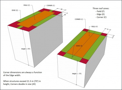
- A roof area that is divided into smaller segments by means of control joints (roof dividers, i.e., a fire wall) or expansion joints, shall be considered one roof area for the purpose of calculating the Specified Wind Loads, unless the height of a control joint or expansion joint exceeds 1 m (39"), in which case the Specified Wind Loads for each roof segment shall be calculated separately (See Figure 3.1.3.2.-B).
- When a building is designed with multiple roof levels (at different elevations), and the roofs are adjacent each other (having a common wall), the Specified Wind Loads for each level, and for each roof area on that level, shall be calculated separately from loads for the adjacent level, unless the elevation difference between adjacent roof levels is less than 1.524 m (5’) (See Figure 3.1.3.2.-B).
- When the shape of a single-level roof varies in width or length, the smallest width dimensions shall be used in the calculation of Specified Wind Loads (Ref. “minimum effective width” as defined in the "British Columbia Building Code", Division B, Part 4, Article 4.1.7.2., "Classification of Buildings").
Figure 3.1.3.2.-B Roofs Adjacent to Each Other
Forming Part of Article 3.1.3.2.
(Click to expand illustration)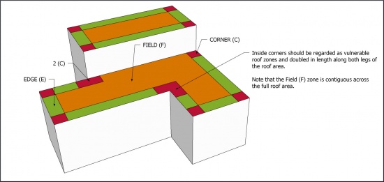
- When a roof area intersects the corner of a wall, the Edge zone on either side of the wall corner must be treated as a roof Corner (2 x C) (Figure 3.1.3.2.-B).
- When an existing roof system is specified for partial replacement, the Design Authority must
- calculate the Specified Wind Loads for the roof,
- determine if securement of the remaining roof components (left in situ) is sufficient to resist the Specified Wind Loads,
- determine a suitable method of securement or have the system of securement engineered, and
- calculate and design securement for any overburden, amenities, or equipment.
- Roof systems should be designed in conjunction with the electrical systems for the building, to avoid unnecessary interference with roof system securement (See also Subsection 2.1.8., "Electrical Cables and Boxes").
- Mansards are a roof system and are therefore subject to the requirements in this Part.
- Securement of an adjoining water-shedding system shall be made in accordance with the requirements in the applicable Standard.
- Wind loads for a roof assembly supporting a vegetated roof system shall be determined in accordance with the requirements of the Building Code and Resistance to Specified Wind Loads | Article 3.1.3.3.] of the “RGC Standard for Vegetated Roofs”.


3.1.3.3. Resistance to Specified Wind Loads
- The wind uplift resistance capabilities of the selected roof system must equal or exceed the Specified Wind Loads calculated for each roof zone to which the system will be applied (see Article 3.1.3.2.).
- Engineered designs to resist wind uplift may refer to the "British Columbia Building Code", Div. B, Appendix C, "Table C-2", which lists various types of loads, including wind loads, for specific reference locations throughout the province.
3.1.3.4. Resistance to Other Loads
- In addition to its capacity to resist Specified Wind Loads, the roof system must be capable of resisting or accommodating
- all anticipated live and dead loads, including (without limitation) other environmental loads, such as rain and snow, expected for the building’s size and location,
- gravity ("drag") loads,
- loads from overburden (See Part 14), and
- thermal expansion and contraction of the roof system components.
- Where the roof is designed to support a vegetated roof system, consideration for other loads shall conform to the requirements in Article 2.1.4.1. of the “RGC Standard for Vegetated Roofs”.
3.1.3.5. Submittals
- Refer to the requirements in Article 1.3.2.4.
3.1.4. Conventionally Insulated Roof Systems
(The requirements in Subsection 3.1.3., "All Systems", shall be read together with the following articles)
3.1.4.1. Securement Against Specified Wind Loads
(See Note A-3.1.4.1.)
- New and fully replaced conventionally insulated systems shall satisfy the requirements of the "British Columbia Building Code" and this Part, and shall be (when applicable)
- an Adhesive Applied Roof System ("AARS"),
- a Partially Attached Roof System ("PARS"), or
- a Mechanically Attached Roof System ("MARS"),
which may be specified as
- a Tested Assembly,
- an Assembly with Proven Past Performance, or
- an assembly with custom-engineered securement.
3.1.4.2. Specifying a Tested Assembly
(See Note A-3.1.4.2.)
- Only roof assemblies that have been tested by qualified facilities wholly independent of roof system manufacturers, using CSA-A123.21, "Standard test method for the dynamic wind uplift resistance of membrane-roofing systems" (latest edition), will be considered valid Tested Assemblies, for the purposes of this Standard (See here for a list of qualified testing agencies).
- The Design Authority is strongly encouraged to specify the application of a Tested Assembly, for any design of a new or fully replaced membrane waterproofing roof system.
- The Design Authority must use only the test observation readings that have been adjusted for the "Safety Factor" (CSA-A123.21, prior to the 2019 edition) or the "Resistance Factor" (CSA-A123.21, 2019 and newer), which must equal or exceed the highest Specified Wind Loads for the roof (this adjusted value is called the Dynamic Uplift Resistance, or DUR. See Figure 3.1.4.2.-A).
- When a Tested Assembly report indicates only one system of securement, that system shall be applied to all roof zones; alternatively, zone-specific securement requirements may be extrapolated by a Registered Professional "skilled in the work concerned", using ANSI-SPRI WD-1, "Wind Design Standard Practice for Roofing Assemblies" (see the "British Columbia Building Code", Division B, Part 5, Notes to Part 5, A-5.2.2.2.(4)).
Figure 3.1.4.2.-A Dynamic Uplift Resistance
Forming Part of Article 3.1.4.2.
(Click to expand illustration)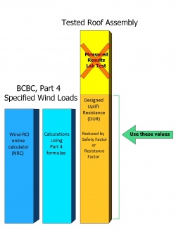
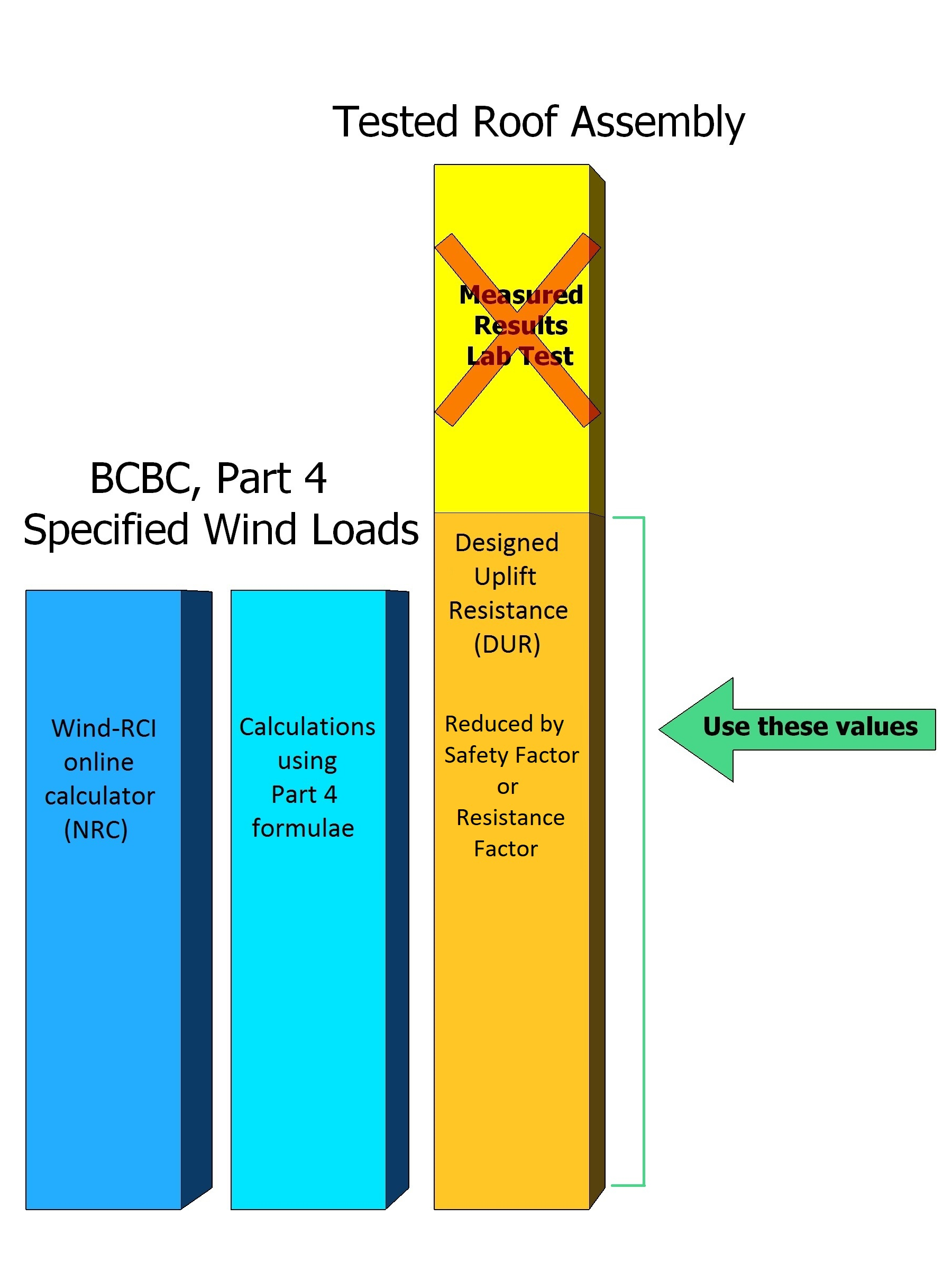
3.1.4.3. Specifying an Assembly with Proven Past Performance
(See the "British Columbia Building Code", Division B, Part 5, Notes to Part 5, A-5.1.4.1.(5) for an expanded explanation of the tests for "proven past performance")
- A new conventionally insulated roof assembly (the new roof assembly) may be designed using a model roof assembly as a reference (the roof Assembly with Proven Past Performance), but only when
- a Tested Assembly cannot be used,
- the material components identified in a Tested Assembly are not accepted by the RoofStar Guarantee Program, and the test report offers no RoofStar-accepted alternates,
- a Tested Assembly is not available because a material or system has not been tested, or because the Specified Wind Loads exceed the capacity of an available or suitable Tested Assembly,
- the model roof assembly
- is an existing roof assembly constructed on a real, existing building (the model building),
- demonstrates resistance to negative wind loads that are the same as, or greater than, the Specified Wind Loads which the new roof assembly must be designed to resist,
- has a history of performance equal to or longer than the expected service life of the new roof assembly, and
- is designed with only RoofStar-accepted materials that possess properties "identical or superior to those of the...assembly used as a reference" (Ref. the "British Columbia Building Code", Division B, Notes to Part 5, Environmental Separation),
- the model building
- is similar in dimensions, exposure, openings, and importance to the building that will support the new roof assembly, and
- is situated in conditions representative of the building that will support the new roof assembly (the term "representative" refers to conditions that include, without limitation, dynamic loads caused by proximity to other structures because of funneling or building harmonics).
- To qualify for a RoofStar Guarantee, a new roof assembly patterned after a model roof assembly and the design using a model roof assembly must be supported with a letter of assurance provided to the Guarantor by the Design Authority, or by the manufacturer of the Assembly with Proven Past Performance, signed by the Principal or a person having the authority of the Principal, stating that the new roof assembly will resist the Specified Wind Loads calculated for the new roof assembly.
- A new roof assembly patterned after a model roof assembly may be used for partial roof replacement.
- Published approvals issued by an insurer or underwriter, or roof assembly designs warranted or guaranteed by anyone other than the Guarantor, do not satisfy the requirements for a roof Assembly with Proven Past Performance.
3.1.4.4. Specifying a Custom-engineered Securement Design
- When, for various reasons, a system of securement cannot be designed using either a Tested Assembly or an Assembly with Proven Past Performance, the securement system must be designed by a Registered Professional "skilled in the work concerned" (See the "British Columbia Building Code", Division C, Part 2, Article 2.2.1.2., "Structural Design").
3.1.5. Uninsulated Systems
(The requirements in Subsection 3.1.3., "All Systems", shall be read together with the following articles)
3.1.5.1. Securement against Specified Wind Loads
- All uninsulated roof systems must be designed to resist displacement by Specified Wind Loads, using the options articulated in Article 3.1.4.1.
- Where air intrusion into the roof assembly could compromise its securement, every roof assembly design must provide guidance for the installation of control layers, particularly where control layers intersect roof drains, penetrations, or assemblies adjacent to the roof (i.e., walls) (Ref. Part 6, "Air and Vapour Controls").
3.1.6. Protected Roof Systems
(The requirements in Subsection 3.1.3., "All Systems", shall be read together with the following articles)
3.1.6.1. Securement of Ballasted Roof Systems
(See Note A-3.1.6.1.. Also see Subsection 9.1.6., "Protected Roof Systems")
- Roof systems secured with stone (gravel) ballast, pavers, or a combination of each, must be designed to resist displacement by Specified Wind Loads, regardless of any overburden the design may call for.
- The securement of all roof systems held in place by ballast must be designed by a registered professional "skilled in the work concerned" ("British Columbia Building Code", Division C, Section 2.2., "Administration"), and ballast rates shall conform to
- the minimum requirements in Table 3.1.6.1. (Ref. Article 3.3.5.1., "Ballasted Systems", and Subsection 9.3.6., "Protected Roof Systems"), or
- extrapolated values using ANSI-SPRI RP-4 (latest edition), "Wind Design Standard for Ballasted Single-ply Roofing Systems".
- Stone ballast size for all ballasted roof systems shall conform to ASTM D7655/D7655M-12, "Standard Classification for Size of Aggregate Used as Ballast for Membrane Roof Systems".
- To facilitate resistance to Specified Wind Loads,
- a filter fabric is required beneath gravel or paver ballast, and
- a protection layer is required beneath crushed ballast.
- On roofs specified to utilize stone ballast, no fewer than two parallel rows of pavers should be considered for Corner and Edge zones, to prevent or reduce wind scouring of the gravel.
- When pavers are selected as ballast for a roof system, the Design Authority must determine the support and placement of pavers to resist displacement by Specified Wind Loads.
- Vegetated roof systems designed as ballast for a protected membrane roof assembly shall be designed in accordance with the requirements in Part 3 of the “RGC Standard for Vegetated Roofs”.
Table 3.1.6.1.
Minimum Requirements for Stone Ballast
Forming Part of Article 3.1.6.1.
(Note: these requirements apply only where no other guidance for stone ballast
has been provied by the Design Authority)
XPS Insulation
ThicknessStone Ballast Required Weight Minimum Ballast Depth
(approximate)†Up to 50.8 mm (2") 60 Kg/M2 (12 lb./sf) 44.45 mm (1-3/4") 76.2 mm (3") 80 Kg/M2 (17 lb./sf) 57.15 mm (2-1/4") 101.6 mm (4") 108 Kg/M2 (22 lb./sf) 76.2 mm (3") 125 mm (5") 132 Kg/M2 (27 lb./sf) 88.9 mm (3-1/2") 152.4 mm (6") 156 Kg/M2 (32 lb./sf) 107.95 mm (4-1/4") 177.8 mm (7") 180 Kg/M2 (37 lb./sf) 125 mm (5") 203.2 mm (8") 204 Kg/M2 (42 lb./sf) 139.7 mm (5-1/2")
- † These minimum requirements should be noted by the registered professional
designing the ballast system.
- † These minimum requirements should be noted by the registered professional
3.1.6.2. Securement of Modified Protected Roof Systems
- Modified protected roof systems shall be secured according to the requirements for conventionally insulated roofs supporting overburden.
3.1.7. Roof Replacement and Alterations
3.1.7.1. Complete Roof System Replacement
- Complete roof system replacement projects must be designed to secure the new roof system against displacement by Specified Wind Loads.
3.1.7.2. Partial Roof System Replacement
- Partial roof replacements must be designed to secure the roof system against displacement by Specified Wind Loads, in keeping with the requirements in Article 3.1.3.2. (See also Article 3.3.6.2.).
- When specifying securement for a partial roof replacement, the securement system must be designed and specified by the Design Authority (See also Subsection 1.1.4., "Replacement and Alterations"); nevertheless, mechanical fastening, when practicable, is the recommended method for securing new materials to an existing roof system (See Note A-3.1.7.2.).
Section 3.2. Materials
3.2.1. Material Properties
3.2.1.1. Substituting Materials Used in a Tested Assembly
(See Note A-3.2.1.1.)
- When a manufacturer's Tested Assembly incorporates materials (and listed alternates) that are not part of the RoofStar Guarantee Program, the Design Authority must identify appropriate substitutions for those materials from the list of RoofStar-accepted Materials, and obtain
- written approval from the technical manager of the manufacturer stating that the substituting material will not reduce the capabilities of the Tested Assembly, or
- a letter of support issued by a registered professional qualified to perform the work in Part 4 of the Building Code (Ref. the "British Columbia Building Code", Division C, Part 2, Article 2.2.1.2., "Structural Design").
- Any material substitution should
- be limited to one (1) material component from the Tested Assembly, but the substitution of more than one material component is permissible provided the substitution complies with the other requirements in this Article, and
- be made in keeping with the decision process flows for MARS, PARS and AARS assemblies published in CSA-A123.21, "Standard test method for the dynamic wind uplift resistance of membrane-roofing systems" (latest edition), "Annex F".
- Because of its nature, a new roof assembly patterned after an Assembly with Proven Past Performance does not qualify for material substitution.
3.2.2. Securement Materials
3.2.2.1. Fasteners
- The minimum requirements in this Article apply to any roof system, regardless of requirements published elsewhere.
- The Design Authority should specify the correct type of fastener, keeping in mind
- pull-out strength, and
- corrosion resistance (contributing factors to fastener corrosion may include dissimilar metal contact, excessive building humidity, corrosive chemicals within components of the roof system, or corrosive elements provided within the building envelope etc.).
- Fasteners must be capable of securing the roof system components to resist Specified Wind Loads.
- Unless otherwise permitted in writing by the manufacturer, fasteners shall be resin-coated, self-drilling screws manufactured with recessed heads, and must be used in combination with plates, as shown in Table 3.2.2.1.
Table 3.2.2.1.
Minimum Fastener and Plate Requirements
Forming Part of Article 3.2.2.1.
(Note: these requirements apply only where no other guidance for fastener and plate types and sizes has been provided by the Design Authority)
| Material | Fastener Size |
Plate |
|---|---|---|
| Deck overlays | #12 | 73.03 mm (2-7/8”) Hexagonal, 76.2 mm (3”) Round or Square |
| Insulation | #12 | 73.03 mm (2-7/8”) Hexagonal, 76.2 mm (3”) Round or Square |
| Insulation Overlays | #12 | 73.03 mm (2-7/8”) Hexagonal, 76.2 mm (3”) Round or Square |
| Membranes | #14 | Proprietary |
3.2.2.2. Adhesives
- Adhesives used to secure any roof system materials must be acceptable to the manufacturer and be capable of resisting Specified Wind Loads.
- Adhesives listed in a selected Tested Assembly
- must be used to secure applicable layers within the roof system, and
- may be substituted only with products listed in the Tested Assembly report.
- In the absence of a Tested Assembly, or for adhered and partially adhered roof assemblies with Proven Past Performance, adhesives used to secure new roofing materials must be acceptable to the manufacturer and must be demonstrably capable of resisting Specified Wind Loads.
- Bitumen used as a hot-applied adhesive must be Type 3 or SEBS.
3.2.2.3. Stone (Gravel) Ballast
(See also Table 3.1.6.1. in Article 3.1.6.1.)
- Stone (gravel) ballast used to secure a roof system must be washed (clean) round or crushed stone and must conform to ASTM D7655/D7655M-12, "Standard Classification for Size of Aggregate Used as Ballast for Membrane Roof Systems", or to Table 3.2.2.3.
- The minimum requirements in this Article must not be reduced except by a written Variance that shall be endorsed in writing by the owner or the owner's representative, and submitted to the RoofStar Guarantee Program as part of the Guarantee record.
| Table 3.2.2.3. Stone Ballast Size and Grades Forming Part of Article 3.2.2.3. |
Nominal size Percentage Passing 38.1 mm (1-1/2") 100% 25.4 mm (1") 70 - 100% 19.05 mm (3/4") 5 - 20 % 12.7 mm (1/2") 0 - 6 % 4.76 mm (3/16") 0 - 2 %
3.2.2.4. Pavers and Pedestals
- Pavers that are partially supported (i.e., with pedestals) should be capable of resisting anticipated loads (i.e., hydraulically pressed concrete pavers).
- Pedestals
- should be adjustable when a level surface is required,
- must be purpose-made, and
- must include an integral spacer rib measuring at least a 3.18 mm (1/8”) in width, to uniformly separate pavers.
Section 3.3. Application
3.3.1. Guarantee Term Requirements
3.3.1.1. RoofStar 5-year Guarantee and RoofStar 10-year Guarantee
- To qualify for a RoofStar 5-year Guarantee or RoofStar 10-year Guarantee, all projects shall comply with the requirements in this Part.
3.3.1.2. RoofStar 15-Year Guarantee
- All projects intended to qualify for a RoofStar 15-year Guarantee shall comply with the requirements in this Standard for a RoofStar 5-year Guarantee or RoofStar 10-year Guarantee, and shall
- conform to the specified design when enhanced roof system securement is required (See Article 3.1.2.1.).
3.3.2. All Systems
3.3.2.1. Securing Systems with Mechanical Fasteners
- Unless otherwise specified by a Tested Assembly, a roof assembly with Proven Past Performance, or a custom-engineered assembly,
- fastener patterns shall conform to the minimum requirements published in Table 3.3.2.1.-B through Table 3.3.2.1.-G,
- the minimum number of fasteners must conform to the requirements in Table 3.3.2.1.-A, and
- fasteners shall be installed at least 152.4 mm (6”) from panel corners, measured from each edge of the panel, but the precise placement of fasteners shall be confirmed with the manufacturer.
- Fasteners used to secure boards from curling, or to secure boards at slope transitions, shall be additional to the minimum number of fasteners and plates required by a Tested Assembly, a roof assembly with Proven Past Performance, a custom-engineered assembly, or the patterns shown in Table 3.3.2.1.-B through Table 3.3.2.1.-G.
- When mechanically attached membranes are installed together with new insulation, the insulation assembly (with or without an insulation overlay) must be held in place independently from the membrane, with no fewer than four (4) fasteners per panel.
- Regardless of where fasteners are used in the roof system, when they penetrate and secure another material to a substrate, mechanical fasteners must conform to the requirements illustrated in Figure 3.3.2.1.-A and shall (unless exceeded by the fastener manufacturer’s published requirements)
- penetrate through the bottom surface of
- steel decks at least 19.05 mm (3/4") (fasteners should penetrate the top flutes only), and
- plywood sheathing by at least 19.05 mm (3/4").
- penetrate into solid dimensional lumber or concrete by at least 25.4 mm (1").
- penetrate through the bottom surface of
- Unless otherwise provided for in a Tested Assembly report, in the documentation for an Assembly with Proven Past Performance, or by a Registered Professional in a custom-engineered securement system, mechanical fastening of panel materials shall conform to the minimum RGC Guarantee historical requirements in Table 3.3.2.1.-A through Table 3.3.2.1.-G.
Figure 3.3.2.1.-A Fastener Penetration Into or Through Deck
Forming Part of Sentence 3.3.2.1.(4).
(Click to expand illustration)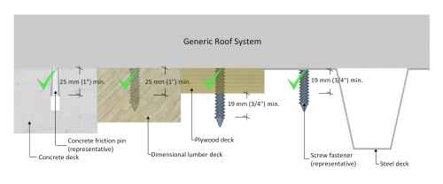

Table 3.3.2.1.-A.
Minimum Requirements for Mechanical Fastening
Forming Part of Article 3.3.2.1.
(Note: Fasteners may be located within 50.8 mm (2") (in any direction) of the positions shown in the diagrams,
but this must be validated by the manufacturer.)
Material Dimensions Roof Zone (Field, Perimeter, Corner) F P C 1219.2 mm x 2438.4 mm (48" x 96") Deck Overlay supporting mechanically attached materials 4 4 4 Insulation or Insulation Overlay supporting mechanically attached materials 4 4 4 Insulation 8 12 15 Insulation Overlays 8 12 15
1219.2 mm x 1828.8 mm (48" x 72") Insulation 6 8 12
1219.2 mm x 1219.2 mm (48" x 48") Insulation 5 6 8
914.4 mm x 1219.2 mm (36" x 48") Insulation 4 6 7
609.6 mm x 2438.4 mm (24" x 96") Insulation 5 6 8
609.6 mm x 1219.2 mm (24" x 48") Insulation 4 4 5
3.3.2.2. Securing Systems with Adhesives
- Adhesives may be used to secure new roofing materials to an existing roof system, provided the specific application procedures and methods are engineered by or for the Design Authority.
- Notwithstanding Sentence (1), the use of adhesive to secure insulation shall conform to Article 7.3.3.1.
3.3.2.3. Securing Roofs with Overburden
- Any overburden, including vegetated roof systems, must be installed in keeping with the designed securement methods and systems specified by the Design Authority, and shall also conform to the the requirements in Part 14 .
NOTE: Table 3.3.2.1.-B through Table 3.3.2.1.-G illustrate fastener patterns and placement based on historical Guarantee requirements, to provide optimum wind uplift resistance. These patterns are to be used only when patterns are not provided in a Tested Assembly, a roof assembly with Proven Past Performance, or in a custom-engineered assembly. Fasteners may be located within 50.8 mm (2") of position shown in diagrams in any direction, but this must be validated by the manufacturer.
Table 3.3.2.1.-B.
Minimum Mechanical Fastening Patterns for
Panels 1219.2 mm x 2438 mm (48" x 96")
Forming Part of Article 3.3.2.1.
(Click on drawing to expand)
1219.2 mm x 2438.4 mm (48" x 96") Field Perimeter Corner 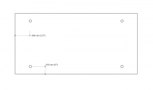 4 Fasteners 4 Fasteners 4 Fasteners
Field Perimeter Corner 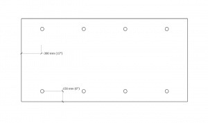 8 Fasteners
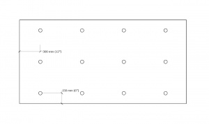 12 Fasteners
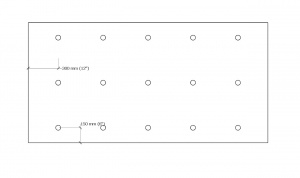 15 Fasteners


Table 3.3.2.1.-C.
Minimum Mechanical Fastening Patterns for
Panels 1219.2 mm x 1828.8 mm (48" x 72")
Forming Part of Article 3.3.2.1.
(Click on drawing to expand)
1219.2 mm x 1828.8 mm (48" x 72") Field Perimeter Corner 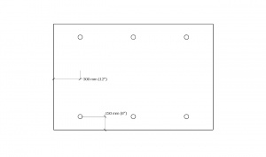 6 Fasteners
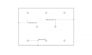 8 Fasteners
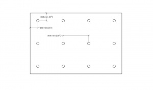 12 Fasteners
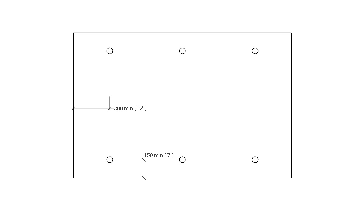


Table 3.3.2.1.-D.
Minimum Mechanical Fastening Patterns for
Panels 1219.2 mm x 1219.2 mm (48" x 48")
Forming Part of Article 3.3.2.1.
(Click on drawing to expand)
1219.2 mm x 1219.2 mm (48" x 48") Field Perimeter Corner 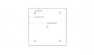 5 Fasteners
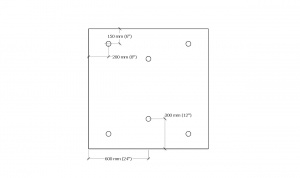 6 Fasteners
 8 Fasteners
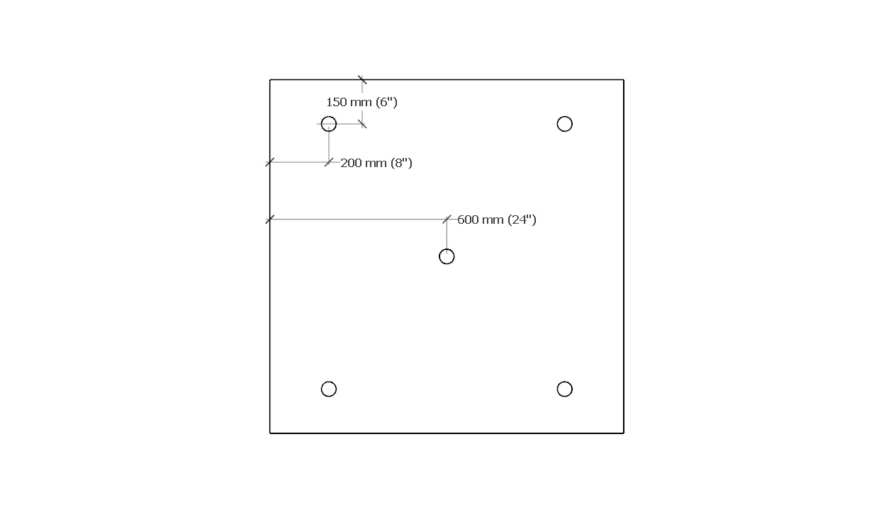
Table 3.3.2.1.-E.
Minimum Mechanical Fastening Patterns for
Panels 914.4 mm x 1219.2 mm (36" x 48")
Forming Part of Article 3.3.2.1.
(Click on drawing to expand)
914.4 mm x 1219.2 mm (36" x 48") Field Perimeter Corner  4 Fasteners
 6 Fasteners
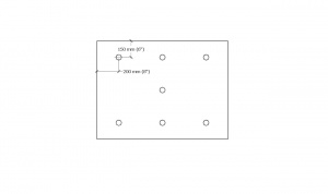 7 Fasteners
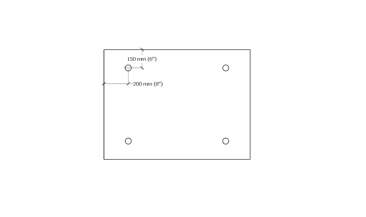
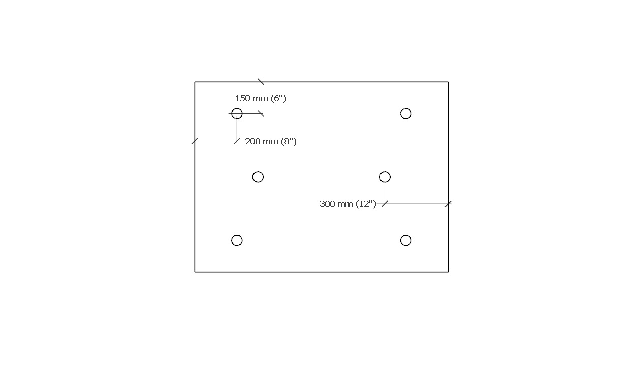

Table 3.3.2.1.-F.
Minimum Mechanical Fastening Patterns for
Panels 609.6 mm x 2438.4 mm (24" x 96")
Forming Part of Article 3.3.2.1.
(Click on drawing to expand)
609.6 mm x 2438.4 mm (24" x 96") Field Perimeter Corner  5 Fasteners
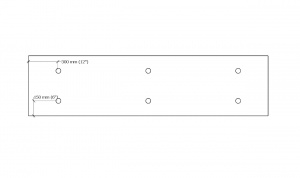 6 Fasteners
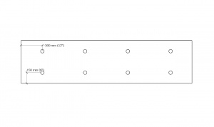 8 Fasteners

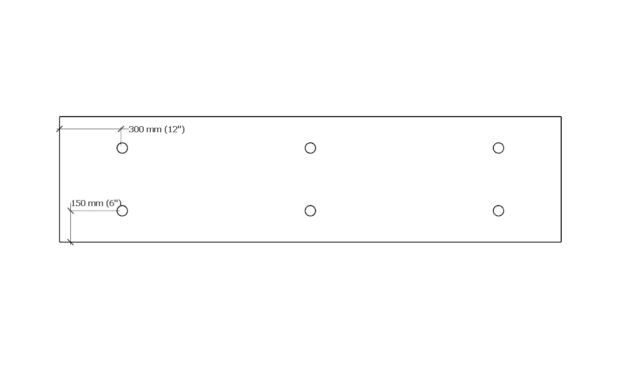

Table 3.3.2.1.-G.
Minimum Mechanical Fastening Patterns for
Panels 609.6 mm x 1219.2 mm (24" x 48")
Forming Part of Article 3.3.2.1.
(Click on drawing to expand)
609.6 mm x 1219.2 mm (24" x 48") Field Perimeter Corner 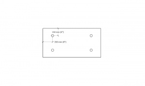 4 Fasteners 4 Fasteners
 5 Fasteners

3.3.3. Conventionally Insulated Roof Systems
(The requirements in Subsection 3.3.2., "All Systems", shall be read together with the following articles)
3.3.3.1. General Requirements
- New and fully replaced conventionally insulated systems must be secured to conform to the Building Code, and shall be capable of resisting displacement by Specified Wind Loads using
- a Tested Assembly,
- an Assembly with Proven Past Performance, or
- an assembly with custom-engineered securement.
3.3.4. Uninsulated Systems
(The requirements in Subsection 3.3.2., "All Systems", shall be read together with the following articles)
3.3.4.1. General Requirements
- All uninsulated roof systems that are not secured with ballast shall conform to the requirements in Article 3.1.4.1. for conventionally insulated systems.
- Uninsulated roof systems secured with stone ballast, pavers or both must be installed following the requirements in Article 3.3.5.1.
3.3.5. Protected Roof Systems
(The requirements in Subsection 3.3.2., "All Systems", shall be read together with the following articles)
3.3.5.1. Ballasted Systems
(Note: the reader must consult the Design and Application requirements for protected roof systems in Part 9).
- Roof systems secured with stone ballast, pavers, or both must be constructed to resist displacement by Specified Wind Loads.
- To facilitate resistance to Specified Wind Loads,
- a filter fabric is required beneath stone or paver ballast,
- a protection layer is required beneath crushed ballast, and
- stone ballast must conform to the specified design.
- Stone ballast shall
- be washed (clean) round or crushed material, and
- be selected (according to the specified design) to resist flotation and Specified Wind Loads.
- Pavers and unit-type masonry, such as brick or paving stones, must be supported by
- purpose-made pedestals conforming to the requirements in Article 3.2.2.4.,
- a proprietary drainage layer overlaid with a filter fabric mat, or
- a drainage layer of loose aggregate (such as pea gravel) measuring at least 25.4 mm (1”) in depth, installed over a filter fabric.
- Pedestals
- must permit at least 12.7 mm (1/2″) of vertical separation between the paver and the underlying substrate, to provide airflow for drying surfaces and assist in leveling,
- should not impede the flow of water or air, and
- should uniformly distribute the dead load of pavers, and other unit masonry products, as well as predicted live loads.
- Pavers must be tied together when specified by the design.
- When a vegetated roof system is used as ballast, the installation shall conform to Part 10 of the “RGC Standard for Vegetated Roofs” (See also Part 3 in the same Standard, concerning design requirements).
3.3.6. Roof Replacement and Alterations
3.3.6.1. Complete Roof System Replacement
- Roof systems that are removed and replaced in their entirety (excluding the air or vapour controls, which may be left in place at the discretion of the Design Authority) must be secured following the requirements for new roof systems.
3.3.6.2. Partial Roof Replacement
- When only a portion of an existing roof system is specified for replacement, the new materials must be secured to resist Specified Wind Loads (See also Subsection 1.1.4., "Replacement and Alterations").
- Mechanical fastening is the most reliable method for securing new materials installed over an existing roof assembly, but when mechanical fastening is not practicable, the system of securement must be
- custom-engineered, or
- patterned after a roof assembly with Proven Past Performance, in keeping with the requirements in Article 3.1.4.3.
© RCABC 2026
RoofStarTM is a registered Trademark of the RCABC.
No reproduction of this material, in whole or in part, is lawful without the expressed permission of the RCABC Guarantee Corp.