
Difference between revisions of "PVC Control Joint (Roof Divider)"
Difference between revisions of "PVC Control Joint (Roof Divider)"
(Created page with "{{Template:RPM Info}} {{DISPLAYTITLE:<span style="position: absolute; clip: rect(1px 1px 1px 1px); clip: rect(1px, 1px, 1px, 1px);">{{FULLPAGENAME}}</span>}} __NOTOC__ <big>...") |
|||
| Line 6: | Line 6: | ||
<big><big>Division D - Construction Details</big></big> | <big><big>Division D - Construction Details</big></big> | ||
<hr> | <hr> | ||
| − | <big><big><big><big><big>PVC | Control Joint (Roof Divider)</big></big></big></big></big> | + | <big><big><big><big><big>PVC | Control Joint (Roof Divider) ([[PVC_Roof_Systems_Standard#10.3.2.3._General Application Requirements for Perimeters and Walls | Article 10.3.2.3.]]; [[PVC_Roof_Systems_Standard#10.3.4.1._Parapets | Article 10.3.4.1.]])</big></big></big></big></big> |
{{Template:Construction Details Header}} | {{Template:Construction Details Header}} | ||
<div class="panel panel-info"> | <div class="panel panel-info"> | ||
| Line 12: | Line 12: | ||
<div class="panel-body"> | <div class="panel-body"> | ||
<div class="col-md-6"> | <div class="col-md-6"> | ||
| + | <br> | ||
<div style="text-align:center; vertical-align:center"> | <div style="text-align:center; vertical-align:center"> | ||
| − | + | [[File:Part 10 - Construction Detail - Control Joint - PVC 1.png | thumb | 700px | link=https://rpm.rcabc.org/images/7/74/Part_10_-_Construction_Detail_-_Control_Joint_-_PVC_1.png | '''Drawing A''']] | |
| − | [[File: | + | |
| − | :Drawing | + | [[File:Part 10 - Construction Detail - Control Joint - PVC 2.png| thumb | 700 px | link=https://rpm.rcabc.org/images/0/04/Part_10_-_Construction_Detail_-_Control_Joint_-_PVC_2.png | '''Drawing B''']] |
</div> | </div> | ||
| − | </div><!-- COL-6 | + | |
| + | </div><!-- COL-MD-6 --> | ||
<div class="col-md-6"> | <div class="col-md-6"> | ||
=== WORK INCLUDED === | === WORK INCLUDED === | ||
| − | ; | + | ;(1) [[PVC Roof Systems Standard#PART_10|'''Control Joint (Roof Divider)''']]: |
| + | :Typically framed with dimensional lumber and plywood on site by the ''Contractor'', or by others (as specified). See [[PVC_Roof_Systems_Standard#10.1.6.2. Control Joints (Roof Dividers) | Article 10.1.6.2.]] concerning permissible design heights for control joints. | ||
| + | |||
| + | :Two models are illustrated here. A ''control joint'' may be as low as 101.6 mm (4”), shown in '''Drawing B''', provided it is not capped with a ''linear metal flashing''. If a metal cap flashing is specified, the minimum height of the ''control joint'' must be 127 mm (5”), shown in '''Drawing A''', and screw fasteners securing the cap flashing must be kept at least 88.9 mm (3-1/2”) above the ''finished roof system surface''. | ||
| + | ;(2) [[PVC Roof Systems Standard#PART_10|'''Roof field membrane''']]: Installed as required in [[PVC_Roof_Systems_Standard#Part_9 | Part 9]], adhered to the sides of the ''control joint'', and mechanically secured to the vertical surface with a ‘term’ bar (illustrated). | ||
| + | ;(2a) [[PVC Roof Systems Standard#PART_10|'''Roof Membrane Securement Strip''']]: | ||
| + | :Proprietary to a single-ply membrane ''manufacturer'' and installed to secure the field membrane at the base of a ''wall'', ''parapet'', expansion joint, or ''control joint''. Not required for SBS-modified bituminous membrane systems. | ||
| + | ;(3) [[PVC Roof Systems Standard#PART_10| '''Membrane flashing''']]: Covers (adhered to) the ''control joint'' and overlaps the field membrane. | ||
| + | ;(4) [[PVC Roof Systems Standard#PART_13|'''Metal Cap Flashing''']]: | ||
| + | :Cap flashing must be designed and installed as required in [[PVC_Roof_Systems_Standard#Part_13 | Part 13]]. | ||
| + | |||
| + | :Note that the cap flashing is sloped at least 2% (mono slope illustrated) when the width of the flashing exceeds 101.6 mm (4”) (Ref. [[PVC_Roof_Systems_Standard#13.1.3.6. Cap Flashing, Counter-flashing, and Reglet Flashing | Article 13.1.3.6., “Cap Flashing, Counter-flashing, and Reglet Flashing”]]). | ||
| + | |||
| + | :Fasteners used to secure metal flashing must be at least 88.9 mm (3-1/2”) above the ''finished roof system surface''. | ||
| + | |||
| + | <hr> | ||
=== RELATED WORK BY OTHERS === | === RELATED WORK BY OTHERS === | ||
| − | ; | + | ;(A) [[PVC Roof Systems Standard#PART_2|'''Acceptable deck''']] |
</div><!-- COL-6-MD --> | </div><!-- COL-6-MD --> | ||
| Line 31: | Line 48: | ||
</div><!-- PANEL --> | </div><!-- PANEL --> | ||
| − | '''NOTE''': See the [[PVC Roof Systems Standard | ''' | + | '''NOTE''': See the [[PVC Roof Systems Standard | '''Standard''']] for additional requirements. |
<hr> | <hr> | ||
| Line 37: | Line 54: | ||
[[PVC Roof System Details|<i class="fa fa-chevron-circle-left fa" ></i> Back to ''PVC Roof System Details'']] | [[PVC Roof System Details|<i class="fa fa-chevron-circle-left fa" ></i> Back to ''PVC Roof System Details'']] | ||
| − | [[ | + | [[Main Page | <i class="fa fa-home fa"></i> Home]] |
{{Template:RPM Page Footer with Copyright and Current Date}} | {{Template:RPM Page Footer with Copyright and Current Date}} | ||
Latest revision as of 20:00, 12 November 2025
Division D - Construction Details
PVC | Control Joint (Roof Divider) ( Article 10.3.2.3.; Article 10.3.4.1.)
| Notice to Reader | |
| Images used in a Construction Detail are representative and not prescriptive, and are not necessarily drawn to scale. They are intended to support the related Standard (Ref. Division A, Article 2.2.1.2.).
The reader may link to the related Article in the detail title, or link to the Standard as it relates to a specific element in the detail. All hyperlinks are displayed blue text. | |
PVC Details
1 WORK INCLUDED
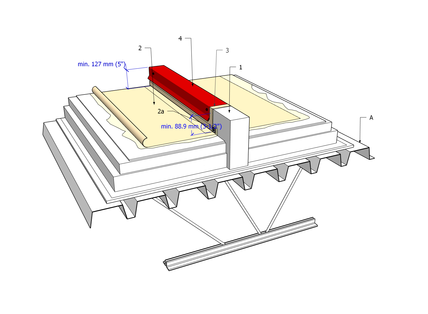
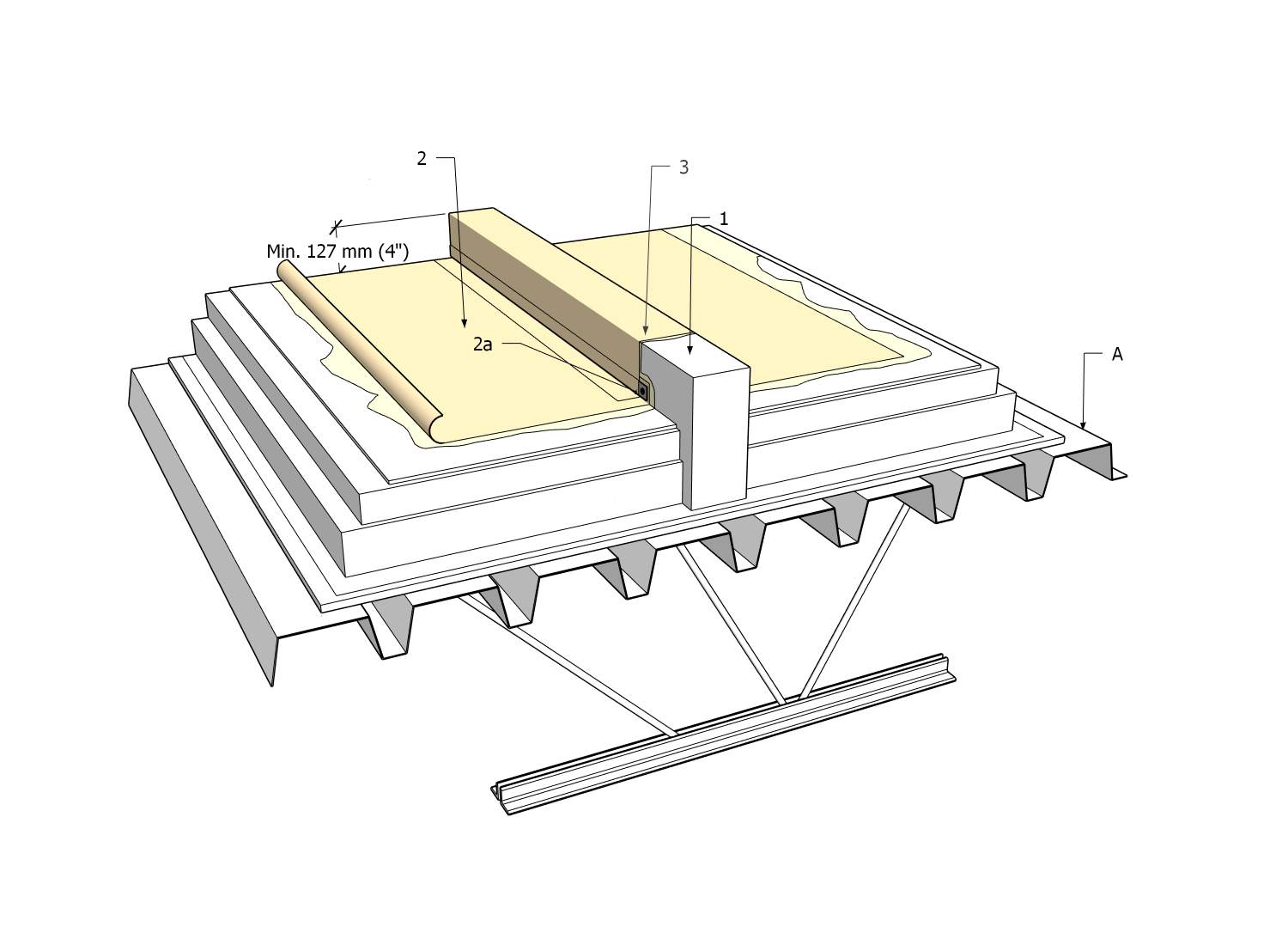
- (1) Control Joint (Roof Divider)
- Typically framed with dimensional lumber and plywood on site by the Contractor, or by others (as specified). See Article 10.1.6.2. concerning permissible design heights for control joints.
- Two models are illustrated here. A control joint may be as low as 101.6 mm (4”), shown in Drawing B, provided it is not capped with a linear metal flashing. If a metal cap flashing is specified, the minimum height of the control joint must be 127 mm (5”), shown in Drawing A, and screw fasteners securing the cap flashing must be kept at least 88.9 mm (3-1/2”) above the finished roof system surface.
- (2) Roof field membrane
- Installed as required in Part 9, adhered to the sides of the control joint, and mechanically secured to the vertical surface with a ‘term’ bar (illustrated).
- (2a) Roof Membrane Securement Strip
- Proprietary to a single-ply membrane manufacturer and installed to secure the field membrane at the base of a wall, parapet, expansion joint, or control joint. Not required for SBS-modified bituminous membrane systems.
- (3) Membrane flashing
- Covers (adhered to) the control joint and overlaps the field membrane.
- (4) Metal Cap Flashing
- Cap flashing must be designed and installed as required in Part 13.
- Note that the cap flashing is sloped at least 2% (mono slope illustrated) when the width of the flashing exceeds 101.6 mm (4”) (Ref. Article 13.1.3.6., “Cap Flashing, Counter-flashing, and Reglet Flashing”).
- Fasteners used to secure metal flashing must be at least 88.9 mm (3-1/2”) above the finished roof system surface.
2 RELATED WORK BY OTHERS
- (A) Acceptable deck
NOTE: See the Standard for additional requirements.
Back to PVC Roof System Details
© RCABC 2026
RoofStarTM is a registered Trademark of the RCABC.
No reproduction of this material, in whole or in part, is lawful without the expressed permission of the RCABC Guarantee Corp.