
Template:SBS - Part 2
Template:SBS - Part 2
Revision as of 21:23, 10 April 2026 by James Klassen (talk | contribs) (Created page with "=={{hilite | Section 2.1. Design || 2021-June-30 }}== ===2.1.1. General=== ====2.1.1.1. Scope==== <ol> <li>The scope of this Part and the Standard shall be as described in ...")
Contents
1 Section 2.1. Design
1.1 2.1.1. General
1.1.1 2.1.1.1. Scope
- The scope of this Part and the Standard shall be as described in Division A, Part 1.
1.1.2 2.1.1.2. Defined Terms
(See Figure 2.1.1.2.-A)
- Words that appear in italics are defined in the Glossary. Additionally, the following terms are used in this Part:
- Common Slope means a roof with a slope 1:3 (4” in 12”, or 18 degrees), up to and including 1:1 (12” in 12”, or 45 degrees).
- Deck overlay means a panel material secured to the supporting deck, to render the deck surface suitable for the installation of roofing materials.
- Extreme Slope means a roof with a slope greater than 21:12 (21” in 12”, or 84 degrees).
- Flat (roof) means a roof with a slope less than 1:6 (2” in 12”, or 9 degrees).
- Low Slope means a roof with a slope 1:6 (2" in 12", or 9 degrees, up to but less than 1:3 (4” in 12”, or 18 degrees).
- Sheathing means a rigid panel material secured directly onto framing.
- Steep Slope means a roof with a slope greater than 1:1 (12” in 12”, or 45 degrees) up to and including 21:12 (21” in 12”, or 84 degrees).
- Supporting deck ("deck") means the "structural surface to which a roof system is applied" (adapted from ASTM D1079-18 Standard Terminology Relating to Roofing and Waterproofing).
- Wall means a structural or non-structural element in a building that vertically separates space. Walls may separate the outside environment from the interior conditioned space of a building, or they may separate one or more interior spaces from each other (adapted from ASTM E631-15, "Standard Terminology of Building Constructions").
- Wall overlay means a panel material secured to the surface of a wall, to render it suitable for the installation of roofing or wall cladding materials.
Figure 2.1.1.2.-A Roof Slope
Forming Part of Article 2.1.1.2.
(Click to expand illustration)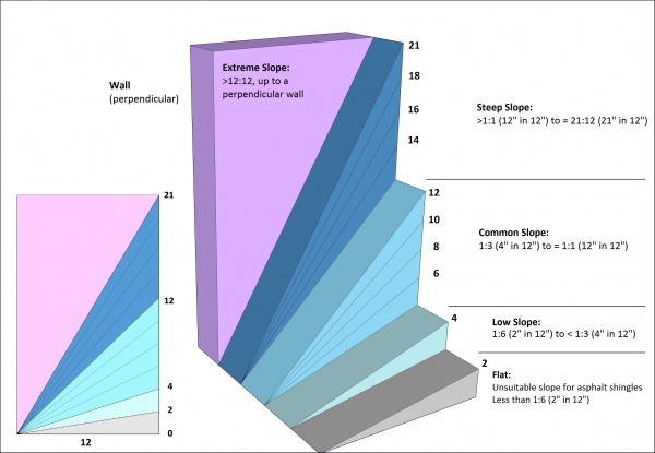

1.2 2.1.2. Guarantee Term Requirements
1.2.1 2.1.2.1. RoofStar 5-year Guarantee and RoofStar 10-year Guarantee
- To qualify for a RoofStar 5-year Guarantee or RoofStar 10-year Guarantee, all projects shall comply with the requirements in this Part.
1.2.2 2.1.2.2. RoofStar 15-Year Guarantee
- To qualify for a RoofStar 15-year Guarantee, all projects shall comply with the requirements in this Part for a RoofStar 5-year Guarantee or RoofStar 10-year Guarantee, and shall (for replacement roofs)
- be designed with a minimum slope of 2% (1/4” in 12”), measured on the primary sloped planes of the roof, and
- incorporate crickets at curbs and sleepers that impede drainage or are wider or longer than 1219.2 mm (48”).
1.3 2.1.3. All Systems
1.3.1 2.1.3.1. General Requirements for Roof Slope
(See Note A-2.1.3.1.)
- The Design Authority must design the slope of a roof to achieve proper drainage and must take into consideration the anticipated deflection and settlement of the structure, which may interfere with drainage.
- While good drainage is desirable but not always perfectly achievable, and roof waterproofing systems generally are not affected by standing water, each project design should incorporate sufficient slope to move water off the roof surface.
- "Sufficient slope", which is subject to conditions that permit evaporation, shall mean that no standing water remains on the roof surface after a reasonable interval following a rainfall (See Note A-2.1.3.1.(4)).
- Roof slope should be increased beyond the minimums published in this Standard when local climate conditions, such as rainfall frequency or severity, result in ongoing or significant ponding conditions (see Article 2.1.3.2. and Article 2.1.3.3. for minimum requirements).
- Drainage (slope toward plumbing drains) should be achieved (in descending order of best practices) with
- four-way slope to drain,
- two-way slope to drain, in combination with crickets between drains,
- slope to a common valley, or to gutters, or
- positive sloping valleys to drains (highly recommended).
- The use of drain sumps, designed to isolate collected water for the drain, is highly recommended, but sloping the perimeters of a sump is not required (See also Article 11.1.3.1., "Principles of Design").
1.3.2 2.1.3.2. Roof Slope for New Construction
- All new construction roofs must be designed and built with a slope of no less than 2% (1/4” in 12”), measured on the primary sloped planes of the roof.
- When the slope of the primary plane of drainage
- is less than 6% (3/4" in 12"), it must be covered with a 2-ply membrane roof system.
- is equal to or greater than 6% (3/4" in 12"), it may be covered with a single-ply membrane roof system.
1.3.3 2.1.3.3. Roof Slope for Replacement Roofing
- Replacement roof systems may qualify for a RoofStar 5-year Guarantee or RoofStar 10-year Guarantee without correcting poor drainage, though the elimination of ponding (standing water) is strongly recommended.
1.3.4 2.1.3.4. Deck Condition and Suitability for Roofing
- The Code having jurisdiction prevails in all cases except where it is exceeded by the requirements published in this Standard.
- Notwithstanding the requirements in this Standard, the RoofStar Guarantee does not cover the supporting deck material or its attachment to the building structure, which is the responsibility of the Design Authority and the building contractor.
- The supporting deck must be dimensionally stable, resist deflection from dead and live loads, and must be capable of accommodating roof system component movement.
- Walls, parapets, curbs, blocking, and penetrations should be constructed or placed by other trades prior to the commencement of roofing work.
1.3.5 2.1.3.5. Drainage Around Obstructions
- Curbs that span 2438.4 mm (96") or more when measured perpendicular to roof slope, across the direction of drainage, should be designed with a cricket to divert water around the curb.
1.4 2.1.4. Reserved
1.5 2.1.5. Roof Decks
1.5.1 2.1.5.1. Steel Roof Decks
(See Note A-2.1.5.1.) (See also Part 9 and Part 10 for substrate preparation requirements)
- Steel decks must be acceptable to the manufacturer and must conform to either
- ASTM Standard Specification A653 / A653M, "Standard Specification for Steel Sheet, Zinc-Coated (Galvanized) or Zinc-Iron Alloy-Coated (Galvannealed) by the Hot-Dip Process": Structural (Physical) Quality, minimum Grade 33, with a design thickness of 22-gauge (0.759 mm) or greater and a minimum zinc coating designation Z275, or
- ASTM Standard Specification A792 / A792M, "Steel Sheet, Aluminum-Zinc Alloy-Coated by the Hot-Dip Process": General Requirements, minimum Grade 33, with a design thickness of 22-gauge (0.759 mm) or greater and a minimum aluminum-zinc alloy coating designation AZ150.
1.5.2 2.1.5.2. Concrete Roof Decks
(See Note A-2.1.5.2.)
- Cast-in-place and precast concrete decks must cure for at least 28 days before receiving an adhered roof membrane ("adhered", as it is used in this requirement, means fully or intermittently bonding any membrane to the deck with an adhesive, hot asphalt (bitumen), or heat), but this limitation may be reduced if
- both the building envelope engineer and the manufacturer expressly permit membrane application within the first 28 days after pouring, and
- their respective signed letters of permission are furnished to the Guarantor forthwith, to be included with the project record.
- Shotcrete-formed concrete decks are not an acceptable substrate for the application of sheet membranes.
1.5.3 2.1.5.3. All Wood Roof Decks
(See Note A-2.1.5.3.)
- Wood decks
- must conform to the material requirements of the Code (see "British Columbia Building Code", Division B, Part 9, Article 9.23.16.2.. "Material Standards"),
- shall be free of loose knots or cracks,
- shall have a moisture content acceptable to the manufacturer (for self-adhered or adhered membranes, moisture content shall not exceed 19%; Ref. Canadian Wood Council, "Moisture and Wood"), and
- shall be secured to other supporting structural elements of the building in keeping with the published requirements of the Code having jurisdiction; specifying the structural suitability of fasteners is the responsibility of the Design Authority.
- Differential edge movements or deflection exceeding 1/360 of the span must be prevented
- by constructing the deck with tongue-and-groove plywood, and supporting the non-grooved edges with joists or solid blocking, or
- by supporting butt joints at unsupported edges with solid blocking.
- All wood board decks to which a membrane will be directly applied must be covered with a properly secured, suitable overlay to
- ensure the integrity of the membrane, and
- protect membranes from wood sap or deck surface irregularities and protruding fasteners.
- Mass timber wood decks do not require an overlay unless specified by the manufacturer.
- Securement of overlaid sheathing shall conform to the requirements for wood decks in this Part.
- All types of wood decks should be roofed promptly after installation.
- Wood roof decks that are uninsulated and vented may be subject to deterioration from condensation and therefore the roof assembly should be designed around the principles in Article 7.1.5.2.
1.5.4 2.1.5.4. Plywood Roof Decks
- Plywood panels should conform to CSA 0121, “Douglas Fir Plywood”, CSA 0151, “Canadian Softwood Plywood”, or CSA 0153, “Poplar Plywood”, but in any event must conform to the requirements published in the Code having jurisdiction (See Note A-2.1.5.4.(1)).
- All plywood decks (notwithstanding the minimum requirements for plywood used to overlay mass timber and wood board decks; see Article 2.1.5.5., Article 2.1.5.6., and Article 2.1.5.7.) shall be constructed to conform to the "British Columbia Building Code" for either Part 3 or Part 9 buildings, and shall be
- at least 12.7 mm (1/2”) thick, unless exceeded by the specified securement design (Ref. Part 3, "Securing the Roof Assembly"),
- free of loose knots and cracks, which are considered defects and must be covered with sheet metal, mechanically fastened in place,
- securely fastened to roof framing, and installed so that the surface grain (plywood) runs at right angles to the roof framing,
- properly gapped between panels, and
- fully supported along all panel edges.
- When a plywood deck is intended to support a protected roof system and a vegetated roof system,
- the deck and any vertical planes that contact the vegetated roof system should be pressure-treated tongue-and-groove plywood at least 19.05 mm (3/4”) thick, but when the existing deck and adjoining wall surfaces are untreated wood, they should be overlaid with no less than one layer of an RGC-accepted deck overlay panel listed in Division C of this Manual (See Note A-2.1.5.1. Suitability of Roof Deck in the "RGC Standard for Vegetated Roofs"), and
- the Design Authority shall be responsible to calculate the anticipated live and dead loads of the system and design suitable approaches to mitigate deflection.
1.5.5 2.1.5.5. Mass Timber Roof Decks
(See Note A-2.1.5.5.)
- Mass timber decks, which include cross-laminated timbers (CLT), nail-laminated timbers (NLT), dowel-laminated timbers (DLT), and traditional glue-laminated timbers (Glulam), are acceptable to the Guarantor and do not require an overlay, but when an overlay is required by the manufacturer it must be plywood conforming to the material requirements in Article 5.2.1.1.
- A mass timber deck that will support a vegetated roof system may be overlaid with a vapour permeable membrane, followed by screw-fastened marine-grade T&G plywood at least 19.05 mm (3/4”) thick, to which the roof system may be applied.
1.5.6 2.1.5.6. Non-veneered Panel Roof Decks
- Non-veneered wood decks are only suitable when the grade
- has been listed as the deck material in a tested assembly using the CSA A123.21 test method, or
- is overlaid with plywood having a minimum thickness of 12.7 mm (1/2”) and secured to the structure (joists or trusses) (See Note A-2.1.5.6.).
1.5.7 2.1.5.7. Wood Board Roof Decks
- Wood board decks should be of sound seasoned lumber, properly secured to the supporting structure.
- Wood board decks (including decks constructed with shiplap lumber) to which an uninsulated membrane roof system will be installed must be overlaid with an acceptable overlay conforming to Article 5.2.1.1., to render the deck suitable for roofing.
1.6 2.1.6. Reserved
1.7 2.1.7. Walls
(See Note A-2.1.7.)
1.7.1 2.1.7.1. General
- Wall surfaces must be clean, dry, and smooth, suitable for the application of roof system materials.
- Wood or steel-stud walls must be sheathed with a material suitable for adhering membranes and securing metal flashings; when sheathing is unsuitable, it must be overlaid with an accepted wall overlay.
- Sheathing is considered a wall surface for the purpose of this Standard.
- Wall surfaces suitable for receiving waterproofing materials must extend beyond the maximum installed height of the waterproofing, but in any event must be installed at least 203.2 mm (8”) above the finished roof system surface (For wall overlays, refer to Article 5.2.1.3.).
- Indirect connections between walls and roofs require a control joint (See Note A-10.1.6.2.).
1.8 2.1.8. Electrical Cables and Boxes
(See Note A-2.1.8. concerning electrical systems, fire and shock hazards, and Rule 12-022 of the Canadian Electrical Code, Part I)
1.8.1 2.1.8.1. New Construction
- Electrical cables, raceways or boxes shall not be installed within a roof assembly (Figure 2.1.8.1.-A).
- Electrical cables, raceways or boxes shall not be installed on the underside of a roof assembly, unless
- the supporting deck structure equals or exceeds 76.2 mm (3”) in thickness (Figure 2.1.8.1.-B), or
- the cables, raceways or boxes are installed and supported so there is a separation of not less than 38.1 mm (1-1/2") measured between the underside of the roof assembly and the electrical installation (Figure 2.1.8.1.-C).
- Notwithstanding either (1) and (2), cables or raceways shall be permitted to pass through a roof assembly for connection to electrical equipment installed on the roof, provided that the passage through the roof is a part of the roof assembly design.
- Electrical cables installed above the roof assembly should be elevated to permit proper support, roof maintenance and future replacement roofing (Figure 2.1.8.1.-D).
Figure 2.1.8.1.-A
Prohibited Installation of
Electrical Conduit
Forming Part of Sentence 2.1.8.1.(1)
(Click to expand)Figure 2.1.8.1.-B
Roof Decks and Electrical Conduit
Installation
Forming Part of Clause 2.1.8.1.(2)(1)
(Click to expand)


Figure 2.1.8.1.-C
Minimum Separation Between Roof Assembly
and Electrical Conduit
Forming Part of Clause 2.1.8.1.(2)(2)
(Click to expand)Figure 2.1.8.1.-D
Electrical Conduit Elevated Above
Roof Assembly
Forming Part of Sentence 2.1.8.1.(4)
(Click to expand)


1.8.2 2.1.8.2. Roof Replacement and Alterations
- If existing electrical cables or boxes do not conform to the requirements in Article 2.1.8.1., the Design Authority must consider the attachment of the roof system above the electrical system, and the requirements set out in Part 3, "Securing the Roof Assembly".
- The Design Authority should
- specify protection of existing electrical cables and boxes (a 4.76 mm (3/16”) steel plate may be used to minimize the possibility of fastener penetration and cutter damage, but protection plates may interfere with mechanical fasteners used to secure the roof system against wind uplift, even for future replacement roofing), and
- provide the building owner with detailed as-built drawings that accurately map the location of electrical cables and boxes.
2 Section 2.2. Materials
2.1 2.2.1. Material Properties
2.1.1 2.2.1.1. Sheathing for Framed Walls
- Framed wall sheathing must be
- moisture resistant fibreglass-faced silicon treated gypsum core board, with a minimum thickness of 12.7 mm (1/2”) (These panels are specifically designed to receive roof membranes and may be installed horizontally or vertically).
- fibre-mat reinforced cement boards with a minimum thickness of 9.53 mm (3/8"), or
- plywood, having a minimum thickness of 12.7 mm (1/2”).
- Where wall sheathing is unsuitable to receive roofing materials, refer to Part 5, "Deck and Wall Overlays".
3 Section 2.3. Application
3.1 2.3.1. Guarantee Term Requirements
3.1.1 2.3.1.1. RoofStar 5-year Guarantee and RoofStar 10-year Guarantee
- To qualify for a RoofStar 5-year Guarantee or RoofStar 10-year Guarantee, all projects shall comply with the requirements in this Part.
3.1.2 2.3.1.2. RoofStar 15-Year Guarantee
- To qualify for a RoofStar 15-year Guarantee, all projects shall comply with the requirements in this Part for a RoofStar 5-year Guarantee or RoofStar 10-year Guarantee, and replacement roofing shall
- achieve a finished slope of at least 2% (1/4” in 12”), when measured on the primary sloped planes of the roof, and
- incorporate crickets at curbs and sleepers that impede drainage or are wider or longer than 1219.2 mm (48”).
3.2 2.3.2. All Systems
3.2.1 2.3.2.1. Construction of Decks and Walls
- Unless otherwise permitted and described in this Standard, the construction of deck and wall structures, and their suitability for the application of roofing materials, is the responsibility of other trades.