
ASM Cylindrical Penetration (Split Panel Flashing)
ASM Cylindrical Penetration (Split Panel Flashing)
Revision as of 20:06, 28 June 2022 by James Klassen (talk | contribs)
Division D - Construction Details
ASM | Cylindrical Penetration (Split Panel Flashing) ( Article 12.3.1.2. and Article 12.3.2.1.)
| Notice to Reader | |
| Images used in a Construction Detail are representative and not prescriptive, and are not necessarily drawn to scale. They are intended to support the related Standard (Ref. Division A, Article 2.2.1.2.).
The reader may link to the related Article in the detail title, or link to the Standard as it relates to a specific element in the detail. All hyperlinks are displayed blue text. | |
ASM Details
 Under Revision

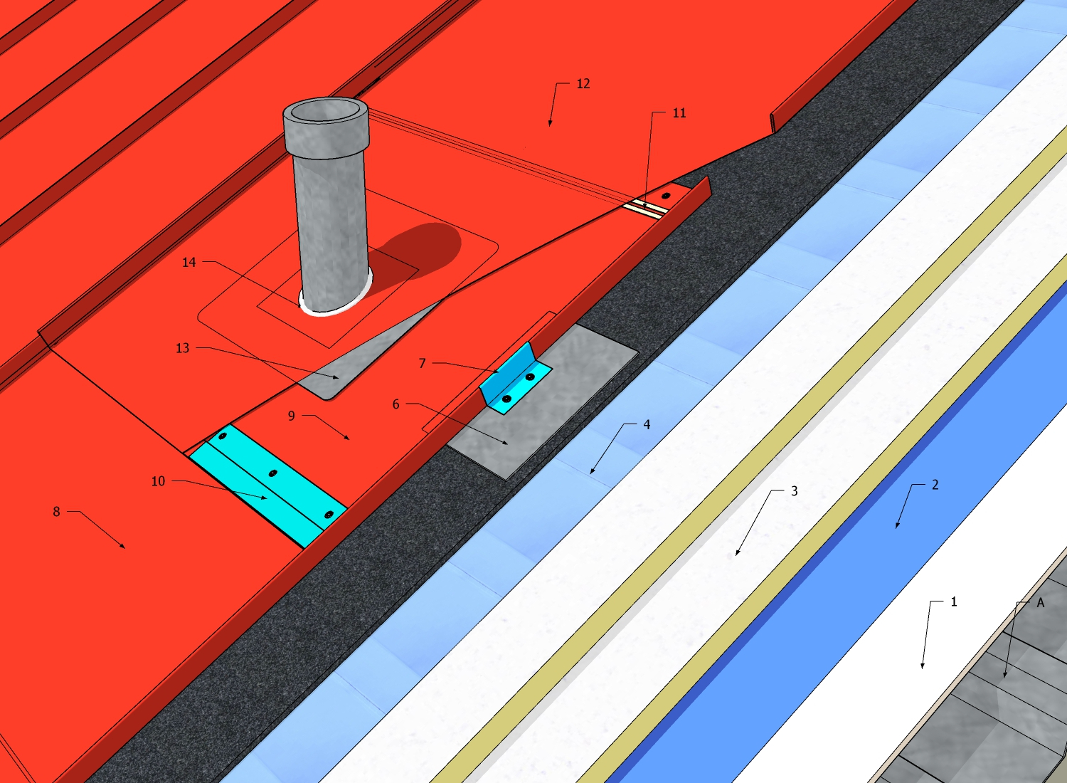
1 WORK INCLUDED
- (1) Deck overlay
- Required for continuous support of the underlayment when the deck is not suitable.
- (2) Underlayment
- The type of underlay required is determined by roof slope.
- (3) Insulation
- Offset and stagger layers 300 mm (12").
- (4) Vapour-permeable separation membrane
- Installed over insulation and required on all insulated Architectural Sheet Metal Roof Systems. The material must be located between the insulation and metal panels/ventilation material.
- (5) Ventilation beneath panels
- A ventilation space is required on slopes less than 1:3; entangled mesh (shown) may be used as void fill. The ventilation space facilitates drying as condensation forms on the underside of the metal panels.
- (6) Bearing plate
- Only thermally non-conductive clips or bars passing through the insulation assembly, or mechanically fastened bearing plates, may be used to secure and support insulation panels, or provide support for panel clips.
- (7) Architectural metal panel clip
- (8) Architectural metal roof panel (lower)
- Lower, installed prior to the pipe flashing, cut hole large enough to allow for movement. Extend 400 mm (16") upslope beyond the pipe.
- (9) Overlap area of lower panel
- Penetration flashing is mounted here, set in an acceptable sealant.
- (10) Spaced Cleat
- Discontinuous cleats (to permit drainage), set in accepted caulking, spaced 50 mm (2") and fastened with compatible non-corrosive flat head screws.
- (11) Sealant
- (12) Architectural metal roof panel (upper)
- Installed after penetration flashing. Cut hole for pipe penetration and turn lower panel end under to hook onto cleat.
- (13) Protrusion Flashing
- Flange set in two continuous beads of accepted caulking.
- (14) Sealant
- Applied around base of penetration flashing.
- (15) Settlement Cap
- Material must match flashing material.
2 RELATED WORK BY OTHERS
- (A) Acceptable Deck
NOTE: See the Standard for additional requirements.
Back to ASM Roof System Details
© RCABC 2024
No reproduction of this material, in whole or in part, is lawful without the expressed permission of the RCABC Guarantee Corp.