
Notes to SBS Standard
Notes to SBS Standard
Revision as of 16:30, 12 November 2021 by James Klassen (talk | contribs) (Created page with "__NONUMBEREDHEADINGS__ <div class="row"> <div class="col-md-3" style="float:right;" id="tocDiv"> __TOC__ </div> <!-- tocDiv --> <div class="col-md-9" id="mainB...")
(Notes are explanatory and non-binding, each provided to support the requirements, guiding principles and recommendations of the Standard.)
Notes to Part 1
- A-1.1.3. (General Requirements)
- Designing a good roof begins with the end in mind and an answer to the essential question, “What purpose will the roof serve?” For example, the roof may
- simply weatherproof the building interior.
- provide a location for building equipment and services.
- support liveable (amenity) spaces.
- There are four principal waterproofing assemblies used on roofs; the choice of system may be influenced by the way in which the roof will be used, and by the type of roof deck:
- Uninsulated Systems - typically insulated below the roof deck.
- Conventionally Insulated Systems - sometimes referred to as Compact Roofs, these are insulated beneath the roof membrane.
- Protected Membrane Roof Systems - also referred to as “inverted”, these systems are insulated above the roof membrane.
- Modified Protected Membrane Roof Systems - these are systems that combine the properties of both a Conventionally Insulated Systems and a Protected Membrane Roof Systems
- Refer to Part 9 of the Standard for membrane and system requirements. For securement requirements, refer to Part 3.
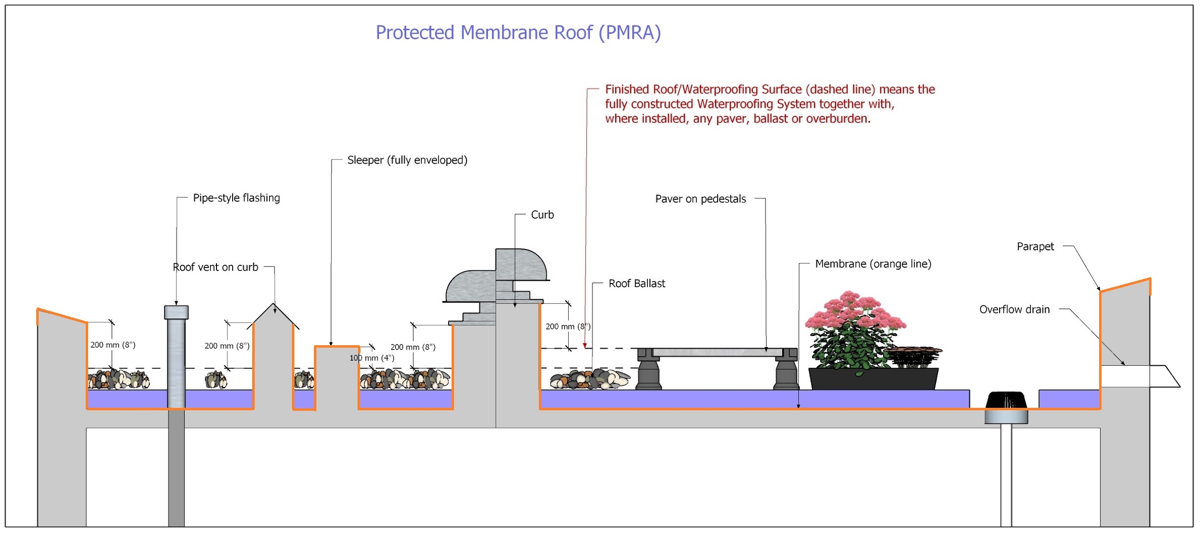
- The Finished waterproofing system is defined by whatever is placed on the membrane, which may be insulation, ballast, pavers or overburden. These materials will displace water and therefore affect the height of membrane flashing needed to prevent water ingress. The definition of Finished waterproofing system is illustrated below in Figures 1.3.2-1 and 1.3.2-2. See also 1.2 Definitions.
Figure 1.3.2-1 (Conventionally Insulated Waterproofing System)(Click to expand) 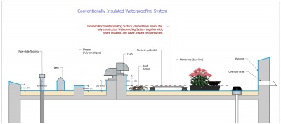

Figure 1.3.2-2 (Protected Membrane Roof System)(Click to expand) 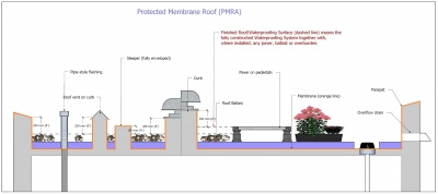
- A-1.1.3.2. (Membrane Integrity Scans)
- An integrity scan is performed after the installation of the roof waterproofing system, before any overburden, equipment or amenity space is installed on top of it. An integrity scan typically uses low-voltage electrical current to detect even the smallest breaches in the roof membrane, but some waterproofing materials may require the use of other technologies to verify the roof system’s integrity. Therefore, Design Authority should specify the appropriate technology, keeping in mind the limitations of each scan and detection methodology, and of the membranes that are specified.
- Neither an integrity scan nor an Electronic Leak Detection (ELD) system are considered Accepted Materials, but firms that provide these services are nevertheless specifically recognized and approved by the RoofStar Guarantee Program.
- A-1.1.4.3. (Electronic Leak Detection)
- Electronic Leak Detection (ELD) utilizes low-voltage electrical current, typically conducted through wires installed in a grid pattern. ELD technologies are used in response to a leak, to isolate its location in order to minimize investigation time and material removal. This can benefit a building owner who will have to bear the costs of demolition or overburden removal when the standard limits of coverage afforded by the RoofStar Guarantee are exceeded by the Project design and construction. ELD technologies may be passive (installed but not monitored) or actively monitored (by the installer, through real-time data collection).
- A-1.1.3.4. (Hot Works)
- When any portion of a waterproofing system is installed with heat, the work is classified as Hot Works. Some tools used in the course of Hot Works can ignite combustible materials, and some building environments are more sensitive to fire than others, such as a building containing or in close proximity to flammable liquids. Hot works may occur during
- tear off (sparks).
- deck preparation (drying wet surfaces).
- cold temperatures (warming materials or surfaces).
- equipment use (sparks within electrical tools, or from cutting, drilling or grinding metal, concrete, stone or other hard surface products).
- membrane installation (with the means of a kettle, hot-air welder or open flame torch).
- A-1.1.4. (Alterations and Additions)
- As a roof ages, is neglected or is damaged, it may lose its ability to perform reliably and effectively, necessitating replacement. Replacement roofing, also referred to as "re-roofing," whether made in whole or in part, should be undertaken with the Quality Assurance and Quality Control provided for under the RoofStar Guarantee Program. Regardless of the approach to replacement roofing, the existing deck structure must meet the pullout resistance rating for mechanical fasteners and must be capable of supporting all dead and live loads. Furthermore, the deck must be capable of supporting any additional dead loads of the new roof system.
- Three types of replacement roofing are contemplated and permitted (with varying degrees of limitations and conditions) under the RoofStar Guarantee Program:
- System replacement - removal and replacement of all roof system components, except for the supporting deck structure.
- Membrane replacement – removal and replacement of the roof membrane, while retaining existing roof system components (i.e. insulation, ballast).
- Recovering - installation of a new membrane over an existing membrane, while retaining some or all of the other roof system materials (NOTE: Recovering is permitted only with a written Variance issued by the Guarantor).
- Qualifying and construction conditions and limitations for each of these replacement options are outlined in Article. Other conditions and limitation may be determined by the Guarantor subject to the nature and specifications of the replacement roofing project.
- A-1.3.3.2. (Workmanship)
- While integrity and functionality of a new roof or grade-level waterproofing is the foundation of a RoofStar Guarantee, it is no less important to ensure that the finished project exhibits excellent workmanship.
Notes to Part 2
- A-2.1.4.1. (Roof Slope)
- Roof slope may be achieved either by designing the roof structure with sloped decks ("structural slope"), or by introducing slope with tapered board insulation (built into the roof system).
- A-2.1.5.1. (Steel Roof Decks)
- Steel decks are constructed of light gauge (usually 22, 20, or 18 gauge) cold-rolled steel sections (panels) that are usually galvanized. In cross-section the panels are ribbed, with the ribs usually spaced at 150 mm (6") O.C. The ribs provide the strength and rigidity of the panels. Steel decks are generally supported by open-web steel joist framing and are welded or mechanically fastened to the framework.
- A-2.1.5.2. (Concrete Roof Decks)
- Concrete decks to which a roof system may be applied include
- Cast-in-place.
- Pre-cast panels.
- Pre-stressed panels.
- Lightweight.
- A-2.1.5.3. (All Wood Roof Decks)
- Wood is a common roof deck construction material that has been used for many years because of its economy, ease of fabrication, lighter construction, and ready availability. Acceptable wood roof decks may include (without limitation)
- wood board (tongue-and-groove, ship-lapped, or splined boards or planks that typically range in thickness from 19 mm to 89 mm (nominal 1" to 4"). Wood board decks may also include Mill Decks which are also called Nail-Laminated Timber decks. These are constructed with a single layer of dimensional boards (dimensions can vary), placed on edge and spiked together to form a Mill Deck. The thickness of the boards is determined by the anticipated loads and spacing of roof joists or trusses.
- plywood (exterior type plywood mechanically fastened to the roof framing).
- non-veneered (oriented strand board, waferboard, etc.).
- laminated timber (typically comprised of crossing layers of dimensional solid wood material, laminated to form a thick, dimensionally stable slab strong enough to support significant structural loads).
- A-2.1.6.1. (Expansion Joints)
- Roof expansion joints, or movement joints, are designed to safely absorb thermal expansion and contraction of materials, or to absorb vibration. They also allow for movement caused by settlement and earthquakes.
- A-2.1.6.2. (Control Joints)
- Control joints (sometimes referred to as roof dividers) are site-built but relatively uncommon for roofs with flexible membranes. They are designed to help control thermal expansion and contraction stresses in the roof system where no structural expansion joint has been provided in the building design. Control joints may be present on older roofs with built-up roof systems, and will have to be taken into consideration by the Design Authority; in some cases, control joints may be eliminated for replacement roofing. Still, control joints may be employed by the Design Authority to control expansion and contraction of any materials in the roof system, or for dividing existing roof areas for phased replacement roofing.
- A-2.1.7. (Walls)
- Walls and roofs intersect either directly (where the wall structurally connects to the roof structure, so that both move together), or indirectly (where the roof structure and the wall structure are independent of each other, so that the movement of one does not affect the other). These locations require an expansion joint.
- A-2.1.8. (Electrical Cables and Boxes)
- Electrical cables (including conduit) or boxes installed inside, on top of, or beneath a roof assembly may expose roofing workers to electrical shock, and may inhibit the installation of some roof systems designed to resist wind uplift. Furthermore, electrical cables on, in or under the roof assembly expose the building and the public to both shock and fire. Hidden electrical wiring and boxed junctions can be extremely difficult to document before work begins, and while some technologies are purportedly accurate in identifying energized circuits before they are damaged, false readings make these technologies less than reliable. During replacement roofing, avoiding damage to electrical circuits from cutters and fasteners is sometimes next to impossible. It is therefore desirable to design buildings with realistic separations between electrical wiring and boxes, and roof assemblies.
- For more about this topic, see the Information Bulletin reissued by Technical Safety BC (formerly BC Safety Authority) in June 2020.
- Currently, neither the Canadian Electrical Code, Part I nor the British Columbia Electrical Code expressly prohibit, nor expressly permit, the installation electrical cables and boxes anywhere in close proximity to a roof assembly. The Design Authority therefore has the latitude to write restrictions concerning the location of electrical installations, and consequently eliminate shock and fire hazards. To do so, apply the following standards when preparing project specifications to qualify for a RoofStar Guarantee.
Notes to Part 3
- A-3.1.1.1. (Scope)
- Wind exerts tremendous forces on a roof system, regardless of roof type. While wind is commonly experienced as a “pushing” force, wind also generates “negative” (pulling or “uplift”) forces, particularly on flat roofs. These powerful forces can, if the roof system is poorly secured to the building’s structural elements, detach a portion or all of a roof system from the building.
- The Code refers to these calculated forces as Specified Wind Loads, which act in concert with the “responses of the roof system…[and therefore] are time-and-space dependent, and thus are dynamic in nature.” (CSA Standard A123.21 Standard test method for the dynamic wind uplift resistance of membrane-roofing systems (latest edition), 4.1). Because of this dynamic interplay between loads and a building’s structural capacities (the load paths between the roof system and other structural elements of the building), the Design Authority must design a roof capable of effectively absorbing and mitigating Specified Wind Loads.
- As stated earlier, the calculation of Specified Wind Loads falls under Division B, Part 4 Structural Design, 4.1.7 Wind Loads, while the securement of the roof components system to resist Specified Wind Loads is governed by Division B, Part 5 Environmental Separation, 5.2.2.2 Determination of Wind Load.
- A-3.1.1.2. (Intent)
- In December 2018 the Province of British Columbia released a revised edition of theBritish Columbia Building Code (the "Code"), based on the 2015 National Building Code of Canada. The 2018 Code includes a considerable expansion of the requirements in Division B, Part 4 (see 4.1 Structural Loads and Procedures, 4.1.7 Wind Load) applicable to the loads exerted on a roof system by wind. The careful reader will note that these Part 4 requirements apply to all Part 3 buildings and to some Part 9 structures.
- While the expansion of Part 4 addresses the calculation of dynamic wind loads experienced by a roof assembly, Part 5 (Environmental Separation) specifies how a roof system should be secured to resist Specified Wind Loads (see 5.2 Loads and Procedures, 5.2.2.2 Determination of Wind Load).
- Article 5.2.2.2 of the Code applies almost exclusively to Conventionally Insulated Roof Systems and is specifically oriented to sheet membrane roof systems. While sheet membrane Conventionally Insulated Roof Systems are prolific and perhaps the most common type of waterproofing roof system, the Code offers little guidance for other roof types, including uninsulated roof systems, liquid membrane systems and systems insulated above the membrane (referred to as “inverted” or “protected”). This Standard incorporates design and construction guidance, even where the Code appears to offer little or no support.
- Proper securement of the roof system, to resist wind uplift loads, is good practice. It also fulfills the design and construction objectives of the Code, to guard public safety, and it supports the design objectives of the RoofStar Guarantee Program, to keep weather outside of the building. In this Part, the reader will find explanatory notes and aids in the design and construction of a roof intended to be Code-compliant.
- A-3.1.4.2. (Specifying a Tested Assembly)
- Tested Assemblies are roof assemblies that have been selected by the membrane manufacturer, installed on a specific deck type, secured using one of three systems, and tested by an independent certified laboratory to determine the limits of the assembly’s ability to resist negative wind pressure (loads), or ‘wind uplift’. Each of the three methods is expressed with an acronym:
- MARS, or Mechanically Attached Roof Systems – these systems are held in place only with mechanical fasteners that are installed at the membrane layer.
- PARS, or Partially Adhered Roof Systems – both mechanical fasteners and adhesives are used as a hybrid method of securement; the membrane is always adhered, using an applied adhesive or heat-welding.
- AARS, or Adhesive Applied Roof Systems – these are membrane roofs secured only with adhesives or heat-welded components.
- A-3.2.1.1 (Substituting Materials Used in a Tested Assembly)
- Tested Assembly values (Dynamic Uplift Resistance) are predicated on a specific combinations (system) of materials. Each material in the system possesses unique "cohesive properties" (internal strength and integrity) and is linked to the adjacent material in a particular way that may depend on a material’s unique "adhesive properties".
- The substitution of material components in a Tested Assembly is not contemplated by CSA-A123.21, but Annex F (a non-mandatory part of the CSA Standard, included at the back of the Standard document for information only) includes three decision processes for MARS, PARS and AARS assemblies, to guide the Design Authority when a substitution is desirable or necessary (ref. A123.21 Standard test method for the dynamic wind uplift resistance of membrane-roofing systems, Annex F (informative) Component swap flow diagrams). Using Annex F as a basis for guidance, the following standards and guiding principles apply for the purpose of issuing a RoofStar Guarantee.
Notes to Part 4
Notes to Part 5
- A-5.1.3.1. (Required Use of Overlays)
- A roof deck overlay (also called a system underlay) is installed as part of the roof system, on the top surface of the roof deck but beneath other roofing materials. These products are most commonly affixed to steel decks to provide a level surface for the roof membrane, to support air or vapour control layers, or to serve as a thermal barrier between the roof deck and combustible insulation. Roof deck overlay materials may also be applied to other types of supporting deck structures, depending on the roof design criteria.
Notes to Part 6
- A-6.1.1.1. (Design)
- Air and vapour control layers, along with thermal barriers, water resistive barriers and water-shedding surfaces, serve to separate the outside environment from the interior environments of a structure. Continuous air control layers are perhaps the most critical. Codes in each jurisdiction, and the National Energy Code (2011), require the selection and proper installation of “a continuous air barrier system comprised of air-barrier assemblies to control air leakage into and out of the conditioned space” (NEC 2011).
- Air control layers regulate and often prohibit the “flow of air through the building enclosure, either inward or outward” (Guide for Designing Energy Efficient Building Enclosures, Homeowner Protection Office). Controlling air flow into and out of conditioned spaces affects the performance of “thermally efficient enclosure assemblies” (ibid), impacts the potential for condensation in between materials, and directly influences rain water penetration of the building envelope.
- Vapour control layers regulate or prohibit the movement of water vapour from one space to another by means of diffusion. Consequently, these control layers are referred to as either vapour-permeable or impermeable. Diffusion is a slow process, in contrast to air movement, and its regulation is not always mandatory or even desirable.
- Any references in this Manual to installation methodologies, and any construction details that show air and vapour control layers, are merely illustrative and not prescriptive. Installers of continuous air and vapour control layer systems are urged to understand and comply with best practices for their application.
Notes to Part 7
- A-7.1.3.1 (Responsibility for Design)
- Insulation materials rely on various standards for the determination of thermal resistance, which means that not all data can be easily compared. Furthermore, not all insulation products perform with consistent thermal resistance as temperature changes, and some insulation performance declines with age. Therefore, refer to the Long-term Thermal Resistance (LTTR) for each insulation product, in relation to the product's placement within the roof assembly and the anticipated outside and interior climates of the building.
- Also see the British Columbia Building Code, Division B, Part 10 (Section 9.25. Heat Transfer, Air Leakage and Condensation Control for structures governed by Part 9), together with relevant requirements in Division A and Division C of the Building Code.
- A-7.1.3.2 (Effective Thermal Resistance and Layering)
- In warm seasons, the roof surface may reach temperatures higher than 85°C (185°F), affecting the performance and stability of some insulation. Consequently, the requirement which limits panel size in single-layer applications ensures that inevitable gaps between adjacent panels are kept to a minimum. Combining insulation types in a roof system may help mitigate these temperature swings and the consequence of thermal contraction. The Design Authority therefore must consider these variables when specifying materials and their installation.
- The Long-Term Thermal Resistance (LTTR) measurement of closed-cell insulation materials remains the standard by which insulation performance is measured. Published R-values should reflect the LTTR of the material. In Canada, two principal standards apply to the accurate measurement of thermal resistance: CAN/ULC-S770 (Standard Test Method for Determination of Long-Term Thermal Resistance of Closed-Cell Thermal Insulating Foams) and CAN/ULC-S704.1 (Standard for Thermal Insulation, Polyurethane and Polyisocyanurate, Boards, Faced).
- A-7.1.3.4 (Tapered Insulation and Crickets)
- The effective thermal resistance of any insulation is dependent on location and other intervening factors (penetrating screw fasteners, for example) which may diminish the performance of the insulation panel. Effective thermal resistance of sloped or tapered insulation is not the same as the average value, using the minimum and maximum thermal resistance of a panel. For help with these calculations, use the RoofStar Effective Thermal Resistance Calculator for Sloped Insulation.
Notes to Part 8
- A-8.1 (Design)
- Insulation overlay boards are installed in most conventionally insulated systems to
- protect heat-sensitive insulation materials from damage by heat and flame.
- protect insulation materials from accidental impact.
- provide dimensional stability to the roof system.
- distribute dead loads from heavy overburdens or equipment installed on top of the finished waterproofing system.
- ensure the membrane performs as it should.
- provide a suitable substrate for membrane application.
- Insulation overlay boards may be mechanically attached or adhered, depending upon the insulation type and the design requirements of the entire roof assembly.
Notes to Part 9
- A-9.1.3.2. (System Securement)
- SBS-modified bituminous membranes are fabricated as rolled sheets and, when specified for use on roofs, are normally designed for application only on Flat or Low Slope structural roof decks and come in a variety of thicknesses and surface finishes. They may be reinforced with different materials (each reinforcement material exhibiting particular properties and offering different benefits), and may each be applied in one or more ways.
- Most SBS-modified bituminous membranes are designed as two separate plies – a base and cap membrane – which are heat-welded together as a 2-ply assembly. Some are self-adhered or adhered to each other and to a substrate with mop-applied hot bitumen or with an adhesive (see below). A third ply is occasionally part of the manufacturer's specified system and may be required or simply is prudent for additional waterproofing protection in certain circumstances.
- Common applications include:
- Mechanically fastened (where the base membrane is affixed to the roof deck with self-drilling screws and load-distributing plates; the cap membrane is then torch-applied or adhered to the base).
- Torch-applied (where torch heat brought to bear on the both the base and cap membranes liquefies the modified bitumen in the membrane so that it bonds with the substrate below).
- Adhered:
- Self-adhering (SA) (using a proprietary adhesive film bonded to the modified bitumen, SA membranes are often adhered with the help of a primer; occasionally, the base membrane is self-adhering, and the cap membrane is then torch-applied to the base).
- Cold-adhered (using bitumen-based or synthetic adhesive, this may sometimes be referred to as 'cold-applied’).
- Hot bitumen adhered (sometimes referred to as 'hot-mopped', 'hot-applied' or simply 'mopped', this application method applies to both the base and cap membranes, or may apply only to the base membrane; the cap, then, is torch-applied to the base membrane).
- A-9.3.3.3.
- "Adhered" refers to a broad category of membranes that may be self-adhering, typically requiring a primer to enhance adhesion (refer to the manufacturer's published instructions), adhered with cold adhesives (synthetic or bitumen-based), or mop-applied with hot bitumen (bitumen that is melted in a kettle). Different requirements apply to each of these, depending on the membrane type, the method of application and the slope of the roof.
Notes to Part 10
Notes to Part 11
- A-11.2.1.2. (Roof Drains and Scuppers)
- Roof drains are comprised mainly of two parts: a bowl or flange that is affixed to the roof deck with mechanical fasteners or a proprietary clamping mechanism; and an integral drain stem that connects the bowl or flange to the leader. Roof drains are sized according to the diameter of the drain stem. The appropriate size and number of roof drains for any given roof area is determined by the relevant building code in force (ref. British Columbia Plumbing Code, Division B, Part 2; Article 2.4.10.4 Hydraulic Loads from Roofs or Paved Surfaces).
- Roof drains can be further classified as internal or external. Internal roof drains are connected to leaders located and connected to a storm building drain or sewer inside the exterior surface of a building. Internal roof drains may be made of cast iron (secured to the roof assembly with clamps) or from copper or aluminum, fashioned from spun components that are welded together and incorporate a flange around the drain bowl.
- External roof drains direct storm water outside the exterior surface of a building. Scuppers and overflow drains are the common types of external roof drains, and may connect to leaders or simply drain freely. Any requirements for leaders and connections to leaders may be found in the applicable municipal and provincial building and plumbing codes (ref. British Columbia Building Code, Division B, 5.6.2.2 Accumulation and Disposal).
Notes to Part 12
Notes to Part 13
Notes to Part 14
- A-14.1. (Design)
- Membrane roof systems may be utilized for more than simple weather protection; they can be occupied by casual or regular users, for gardening, playing, lounging, or other leisure activities. Roofs that serve as amenity spaces require that the Design Authority pay particular attention to the system selection itself and, especially, to the protection of the roof membrane.
- A Conventionally Insulated System is not appropriate for all types of use or roof coverings. For example, the designed live loading for occupied spaces, or the weight of a roof covering, may require the Design Authority to specify particular materials, and consequently to design a roof as a Protected Membrane Roof System. Furthermore, some roof coverings require maintenance that may result in damage to Conventionally Insulated Systems; Protected Membrane Roof Systems shield the sensitive membrane from this inevitability.
- A Protected Membrane Roof System (often referred to as an "inverted roof") offers the designer many benefits, including
- longer lasting membranes.
- capacity for heavier dead and live loads.
- only one control layer to seal and join with the rest of the building envelope.
- fewer waterproofing challenges around penetrations.
- the capacity for electronic leak detection (whether passive or monitored).
- A-14.1.4.3. (Gravel)
- Gravel used as a roof covering is different from its function as ballast on a Protected Membrane Roof System or Modified Protected Membrane Roof System; gravel used as ballast is considered a means of securement and is covered in Part 3 SECURING the ROOF ASSEMBLY and in Part 9.
© RCABC 2021
No reproduction of these Standards, in whole or in part, is lawful without the expressed permission of the RGC Guarantee Program.