
SBS 2-Part Retrofit Flashing (Cable Penetration)
SBS 2-Part Retrofit Flashing (Cable Penetration)
Revision as of 18:24, 27 June 2022 by James Klassen (talk | contribs)
Division D - Construction Details
SBS | Penetration Flashing (2-Part Retrofit) ( Article 12.3.2.1.)
| Notice to Reader | |
| Images used in a Construction Detail are representative and not prescriptive, and are not necessarily drawn to scale. They are intended to support the related Standard (Ref. Division A, Article 2.2.1.2.).
The reader may link to the related Article in the detail title, or link to the Standard as it relates to a specific element in the detail. All hyperlinks are displayed blue text. | |
SBS Details
- Click below for a printable version of this page (under development)

1 WORK INCLUDED
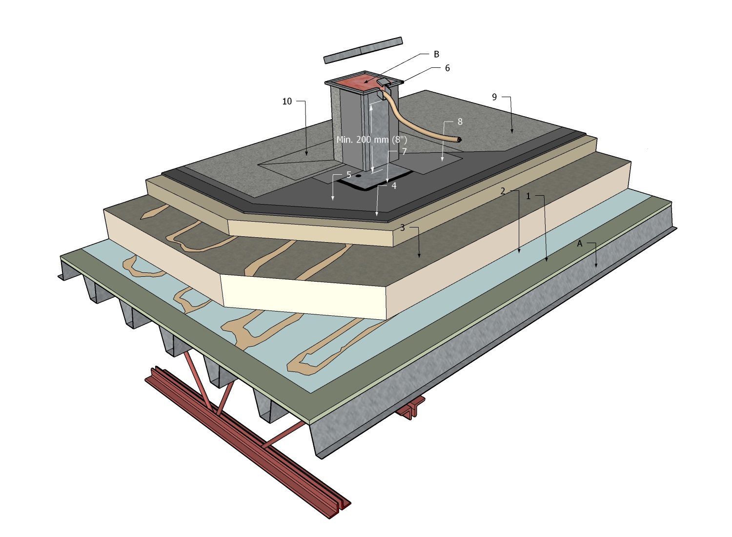
- (1) Supporting Deck Overlay
- Optional, depending upon deck condition and roof system requirements.
- (2) Air or Vapour Control Layer
- Installed following the requirements of Part 6 in this Standard. Tie in the control layers with membranes installed by other trades, to preserve continuity of the building enclosure (2a).
- (3) Insulation
- Installed in staggered and offset layers, and secured in accordance with the design of the system, which is based on the British Columbia Building Code, Part 4 and Part 5, and on Part 3 of the RoofStar Guarantee Standards for the membrane system type.
- (4) Insulation Overlay
- Subject to the requirements of Part 8 in the RoofStar Guarantee Standards for the membrane system type.
- (5) Field Membrane (field)
- Mechanically attached, torch-applied, adhered (shown) or self-adhered. See Tables 9.1 for acceptable membrane types and securement options. See 9.3 for application requirements.
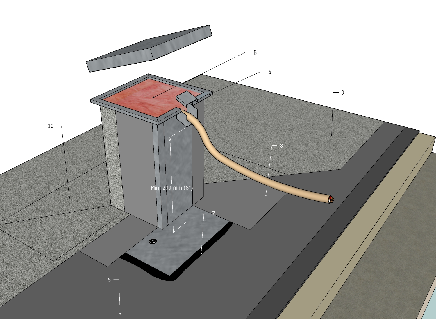
- (6) Two-part Penetration Cable Flashing
- May be proprietary or shop-fabricated from galvanized sheet metal, consisting of two parts that are riveted together in the field, secured to the roof assembly and then ‘stripped’ into the field membrane to waterproof the flashing. This type of flashing may be adapted in its design to accommodate a pipe that turns horizontally to the roof field plane. The exit point for the penetration must be shielded with a hood and sloped downward to shed water. Secure separate lid with screw-type fasteners.
- See 11.2.3 Curbs and Penetration Flashings for fabrication standards.
- (7) Mastic
- Applied to area receiving metal penetration flashing. See 11.3.3.1 (12)(1).
- (8) Base Membrane Flashing (target patch)
- Cut from a single piece of self-adhering or torch-applied base membrane material, it is fashioned with a hole to fit around the penetration flashing and is sealed to the flashing and the roof field. The target patch must cover the flashing flange and extend beyond the edge of the flange, onto the field base membrane, by at least 100 mm (4”). See 11.3.3.1 (12) for all applicable standards.
- (9) Cap Membrane (field)
- Granule-surfaced membrane. See Tables 9.1 and 9.2 for acceptable cap membrane types and their securement options. See 9.3 for application requirements.
- (10)Cap Membrane (flashing)
- Granule-surfaced membrane, installed following the standards published in Part 11.
2 RELATED WORK BY OTHERS
- (A) Acceptable Supporting Deck Structure
- (B) Fibreglass insulation
- Cavity fill, to inhibit condensation inside the flashing.
NOTE: See the Standard for additional requirements.
Back to "SBS" Roof System Details
© RCABC 2024
No reproduction of this material, in whole or in part, is lawful without the expressed permission of the RCABC Guarantee Corp.