
SBS Conventionally Insulated System (alternate)
SBS Conventionally Insulated System (alternate)
Revision as of 17:56, 7 September 2021 by James Klassen (talk | contribs)
Division D - Construction Details
SBS 1.3.1-2 Conventionally Insulated System (alternate)
| Notice to Reader | |
| Images used in a Construction Detail are representative and not prescriptive. Nor are they necessarily drawn to scale. Rather, they are provided to visually convey the requirements of the Standard they represent. Unless otherwise required by the Standard, dimensions, the selection of materials and their application remains the responsibility of the Design Authority. The full text of the referenced requirements in the Standard may be read by using the blue hyperlinks | |
SBS Details
- Click below for a printable version of this page (under development)

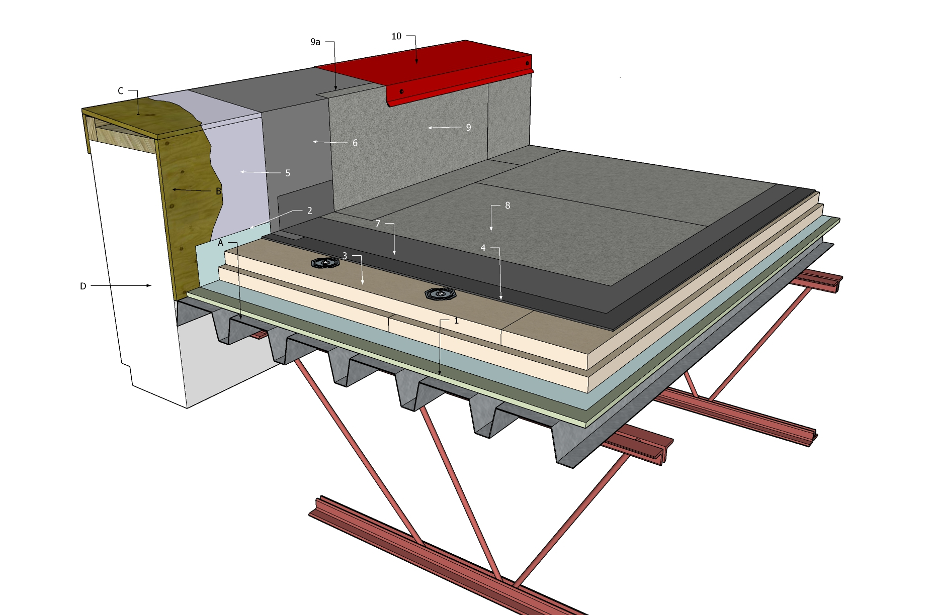
1 WORK INCLUDED
- (1) Supporting Deck Overlay
- Optional, depending upon deck condition and roof system requirements.
- (2) Air or Vapour Control Layer
- Installed following the requirements of Part 6 in this Standard.
- (3) Insulation
- Installed in staggered and offset layers (not fully illustrated), and secured in accordance with the design of the system, which is based on the British Columbia Building Code, Part 4 and Part 5, and on Part 3 of the RoofStar Guarantee Standards for the membrane system type.
- (4) Insulation Overlay
- Subject to the requirements of Part 8 in the RoofStar Guarantee Standards for the membrane system type.
- (5) Primer
- As required by the membrane manufacturer.
- (6) Base Membrane (pre-flashing, as illustrated)
- Base membrane flashing is applied before the field membrane (pre-flashing), and is carried vertically up a wall or parapet at least 200 mm (8”); on parapets, carry the base membrane flashing over the outside face of the parapet at least 50 mm (2”) and secure it (see 10.3.5.1 (2)). Extend base membrane flashing onto the field substrate at least 100 mm (4”) (greater if required by the membrane manufacturer). See also Figure 10.2 (a through d) for sequential illustrations.
- (7) Base Membrane (field)
- Pre-flashing approach (Illustrated). Base field membrane is installed on a suitable, prepared substrate. See 9.3 for application requirements. If permitted by the membrane manufacturer, the field membrane may be turned up at the ends at least 100 mm (4”) (see illustration above), to protect any vulnerabilities at the change in plane. Also see 10.3.3 for other application approaches.
- (8) Cap Membrane (field)
- Granule-surfaced membrane, which may be adhered, self-adhered or heat-welded. See Tables 9.1 and 9.2 for acceptable cap membrane types and their securement options. See 9.3 for application requirements.
- (9) Cap Membrane (flashing)
- Extended vertically past the termination of the base membrane flashing, to provide a positive seal at the top edge. Membrane may be terminated at the top of the vertical plane or turned onto the top of the parapet as required by the manufacturer (9a).
- (10) Metal Cap Flashing
- Fabricated and secured according to the requirements in Part 13 METAL FLASHINGS.
2 RELATED WORK BY OTHERS
- (A) Acceptable Deck
- (B) Suitable Wall Sheathing
- If and as required.
- (C) Sloped Parapet Top
- Sloped to roof where parapet is over 100 mm (4") in width.
- (D) Wall or Parapet Structure
NOTE: See the Standard for additional requirements.
Back to "SBS" Roof System Details
© RCABC 2024
No reproduction of this material, in whole or in part, is lawful without the expressed permission of the RCABC Guarantee Corp.