Difference between revisions of "LMF Metal Cap Flashing (joints)"
Difference between revisions of "LMF Metal Cap Flashing (joints)"
| Line 20: | Line 20: | ||
(5) <b>Metal Cap Flashing: </b>Fastened with continuous concealed clips or cladding screws evenly spaced between seams. See {{hilite | <i>RGC Guarantee Standard A6.10 || 2016-November-19 }} for requirements.</i> | (5) <b>Metal Cap Flashing: </b>Fastened with continuous concealed clips or cladding screws evenly spaced between seams. See {{hilite | <i>RGC Guarantee Standard A6.10 || 2016-November-19 }} for requirements.</i> | ||
| + | |||
| + | |||
| + | |||
| + | |||
| + | |||
| + | |||
Further detail on fastening of flashing is detailed in the SMACNA Manual referenced in Section 10.2. | Further detail on fastening of flashing is detailed in the SMACNA Manual referenced in Section 10.2. | ||
Revision as of 22:11, 19 August 2016
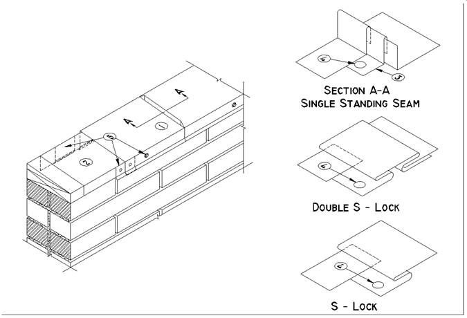
END JOINTS in metal flashings are made using any one of the joints shown in this section, providing the following rules are complied with:
(1) Expansion: Allowances should be made for expansion and contraction. Soldered joints are not acceptable.
(2) Underlayment: Membrane under cap flashing. See RGC Guarantee Standard A5.6
(3) Clips: Standing seams are fastened to wood blocking before applying the following length, using nails and clips.
(4) Fasteners: S-locks and Double S-locks are nailed through the single leaf before applying the following length. See RGC Guarantee Standard A6.8
(5) Metal Cap Flashing: Fastened with continuous concealed clips or cladding screws evenly spaced between seams. See RGC Guarantee Standard A6.10 for requirements.
Further detail on fastening of flashing is detailed in the SMACNA Manual referenced in Section 10.2.
NOTE: Refer to RoofStar Guarantee Standards for additional requirements.

