Difference between revisions of "LMF Metal Cap Flashing (joints)"
Difference between revisions of "LMF Metal Cap Flashing (joints)"
| Line 8: | Line 8: | ||
<div style="text-align:center; vertical-align:center"> | <div style="text-align:center; vertical-align:center"> | ||
[[File:10.2.1.jpg|class=img-responsive]] | [[File:10.2.1.jpg|class=img-responsive]] | ||
| − | |||
| − | |||
| − | |||
| − | |||
| − | |||
| − | |||
</div> | </div> | ||
</div><!-- COL-MD-6 --> | </div><!-- COL-MD-6 --> | ||
Revision as of 19:45, 5 November 2019
| RoofStar Guarantee Standards are blue-linked |
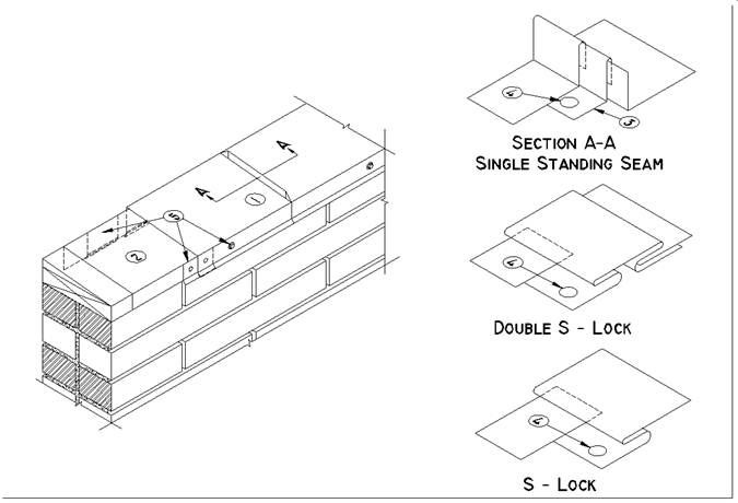
END JOINTS in metal flashings are made using any one of the joints shown in this section, providing the following rules are complied with:
(1) Expansion: Allowances should be made for expansion and contraction. Soldered joints are not acceptable.
(2) Underlayment: Membrane under cap flashing. See, for example, SBS Roof Systems, 10.3 Application.
(3) Clips: Standing seams are fastened to wood blocking before applying the following length, using screws and clips.
(4) Fasteners: S-locks and Double S-locks are screwed through the single leaf before applying the following length. See SBS Roof Systems - 13. Perimeter Flashing: Metal.
(5) Metal Cap Flashing: Fastened with continuous concealed clips or cladding screws evenly spaced between seams. See SBS Roof Systems - 13. Perimeter Flashing: Metal.
Further detail on fastening of flashing is detailed in the SMACNA Manual referenced in the RoofStar Guarantee Standards sections of any of the Low Slope Membrane Roof Systems sections.
NOTE: Refer to RoofStar Guarantee Standards for additional requirements.

