Difference between revisions of "SBS Roof System Details"
Difference between revisions of "SBS Roof System Details"
m (James Klassen moved page Section:SBS Construction Details to SBS Construction Details) |
(→SBS Construction Details) |
||
| Line 1: | Line 1: | ||
| − | |||
| − | |||
The drawings contained within this section are intended to represent a variety of modified bituminous roof system designs while remaining generic with regards to manufacturers’ specific application specifications. They do not represent all possible manufacturer application roof system designs. Consult manufacturers’ specifications and RGC Guarantee Standards to develop a system acceptable to both the manufacturer and RGC. | The drawings contained within this section are intended to represent a variety of modified bituminous roof system designs while remaining generic with regards to manufacturers’ specific application specifications. They do not represent all possible manufacturer application roof system designs. Consult manufacturers’ specifications and RGC Guarantee Standards to develop a system acceptable to both the manufacturer and RGC. | ||
Revision as of 18:50, 25 November 2015
The drawings contained within this section are intended to represent a variety of modified bituminous roof system designs while remaining generic with regards to manufacturers’ specific application specifications. They do not represent all possible manufacturer application roof system designs. Consult manufacturers’ specifications and RGC Guarantee Standards to develop a system acceptable to both the manufacturer and RGC.
For further information about flexible membrane system designs, see Section 2.1.3 Guarantee standards for Flexible Membrane Roofing Systems, Section 5 Flexible Membrane Roofing Systems and Section 8 Construction Details.
Modified Bituminous Membrane Construction Details
- D1.7.1 Insulated Steel Deck: Generic Conventional Assembly
- D1.7.2 Cant Edge
- D1.7.3 Protected Membrane
- D1.7.4 Curb Opening
- D1.7.5 Clamping Copper Drain
- D1.7.6 Two Part Cable Flashing
- D1.7.7 Mechanical Curb Opening
- D1.7.8 Pre-Curb Planter Wall
Click on any one of the tabs to the right to see details for each detailed application of SBS roofing
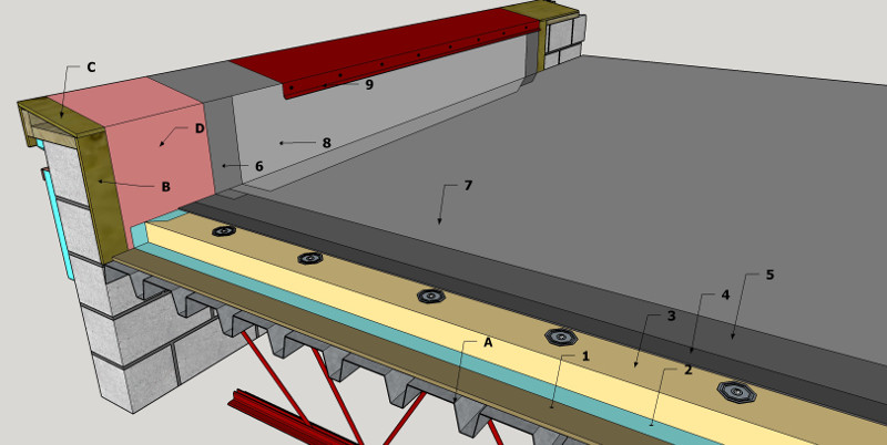
1 MODIFIED BITUMINOUS MEMBRANE:INSULATED STEEL DECK GENERIC CONVENTIONAL ASSEMBLY
1.1 WORK INCLUDED
- (1) Gypsum Board
- Required when insulation is too thin to span flutes of steel decking (see RGC Guarantee Standard A2.5) or when required as a thermal barrier by design authority.
- (2) Vapor Retarder
- If required by design authority.
- (3) Insulation
- Mechanically fastened. (See Section 2.2 for accepted materials and Section 2.1.1 RGC Guarantee Standards A4.3 and A4.4.2).
- (4) Overlay Board
- Asphalt adhered or mechanically fastened. Two layers required over heat-sensitive insulation. (See RGC Guarantee Standard C4.1)
- (5) Base Sheet
- Adhered to overlay board using asphalt, cold adhesive, self-adhered, mechanical attachment or torch applied according to manufacturer’s specification. Torching directly to wood surfaces is not permitted.
- (6) Base Sheet Flashing
- Adhered according to manufacturer’s specifications using cold adhesive, hot asphalt self-adhered or torch applied to cover boards, or mechanically attached membrane. Torching directly to wood surfaces is not permitted. Must be carried over to outside of parapet or minimum 200 mm (8") above finished roof surface. (See RGC Guarantee Standards Section 2.1.1, A5.6, and Section 2.1.3, C8.5).
- (7) Cap Sheet
- Applied according to manufacturer’s printed instructions, all options.
- (8) Cap Sheet Flashing
- Applied according to manufacturer’s printed instructions to top of parapet or minimum 200 mm (8") above finished roof surface. All options.
- (9) Metal Flashing
- As required by RGC Guarantee Standards. (See RGC Guarantee Standard A6.9 and A6.10)
1.2 RELATED WORK BY OTHERS
- (A) Acceptable Steel Deck
- (B) Plywood Backing
- Required on rough surfaces or where adhesive is asphalt. Must be primed.
- (C) Wood Blocking
- Sloped to roof where parapet is over 100 mm (4") in width. Must be primed.
- (D) Primer
- Prime wood substrate to receive self-adhesive base membrane stripping.
NOTE: Refer to RGC Guarantee Standards for additional requirements.
1 MODIFIED BITUMINOUS MEMBRANE: CANT EDGE
1.1 WORK INCLUDED
- (1) Vapor Retarder
- If required by design authority.
- (2) Insulation
- Mechanically fastened where deck type permits. (See list of accepted materials in Section 2.2). (See Section 2.1.1 RGC Guarantee Standard A4.4
- (3) Overlay Board
- Asphalt adhered or mechanically fastened. Two layers required over heat-sensitive insulation. (See RGC Guarantee Standard C4.1)
- (4) Base Sheet
- Adhered to overlay board using asphalt, cold adhesive, self-adhered, mechanical attachment or torch applied according to manufacturer’s specification. Torching directly to wood surfaces is not permitted.
- (5) Base Sheet Flashing
- Adhered according to manufacturer’s specifications, using cold adhesive, hot asphalt self-adhered or torch applied to cover boards, or mechanically attached membrane. Must be carried over to outside of fascia. Torching directly to wood surfaces is not permitted. (See RGC Guarantee Standards Section 2.1.1, A5.6, and Section 2.1.3, C8.5).
- (6) Cap Sheet
- Applied according to manufacturer’s printed instructions and RGC Guarantee Standards.
- (7) Cap Sheet Flashing
- Applied according to manufacturer’s printed instructions and RGC Guarantee Standards up to the top of cant.
- (8) Metal Flashing
- As required by RGC Guarantee Standards. (See RGC Guarantee Standard A6.9 and A6.10)
1.2 RELATED WORK BY OTHERS
- (A) Acceptable Deck
- Smooth, dry and clean.
- (B) Fascia
- Optional.
- (C) Wood Blocking
- Equal to height of insulation and overlay board, primed wherever in contact with asphalt.
NOTE: Refer to RGC Guarantee Standards for additional requirements.
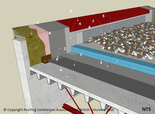
1 MODIFIED BITUMINOUS MEMBRANE: PROTECTED MEMBRANE
1.1 WORK INCLUDED
- (1) Base Sheet
- Adhered to deck using asphalt, cold adhesive, self-adhered, torch applied membrane or loose laid according to manufacturer’s specification and to RGC Guarantee Standards.
- (2) Base Sheet Flashing
- Adhered according to manufacturer’s specifications using cold adhesive, self-adhered or torch applied to cover boards, or mechanically attached membrane. Torching directly to wood surfaces is not permitted. Must be carried over to outside of parapet or minimum 200 mm (8") above finished roof surface. (See RGC Guarantee Standards Section 2.1.1, A5.6, and Section 2.1.3, C8.5).
- (3) Cap Sheet
- Applied according to manufacturer’s printed instructions and RGC Guarantee Standards.
- (4) Cap Sheet Flashing
- Applied according to manufacturer’s printed instructions and RGC Guarantee Standards to top of parapet or minimum 200 mm (8") above top of finished roof surface.
- (5) Insulation
- See list of accepted materials in Section 2.2.
- (6) Filter Fabric
- Metal base flashing required. (See RGC Guarantee Standard A6.9.1.2)
- (7) Ballast
- Gravel or concrete paving tiles. (See RGC Guarantee Standards Section 2.1.1, A5.2)
- (8) Metal Flashing
- As required by RGC Guarantee Standards. (See RGC Guarantee Standard A6.9 and A6.10)
1.2 RELATED WORK BY OTHERS
- (A) Acceptable Deck
- Smooth, dry and clean concrete, coated with proprietary primer.
- (B) Plywood Backing
- Required on rough concrete or where stripping adhesion is asphalt. Must be primed.
- (C) Wood Blocking
- Sloped to roof where parapet is over 100 mm (4") in width.
NOTE: Refer to RGC Guarantee Standards for additional requirements.
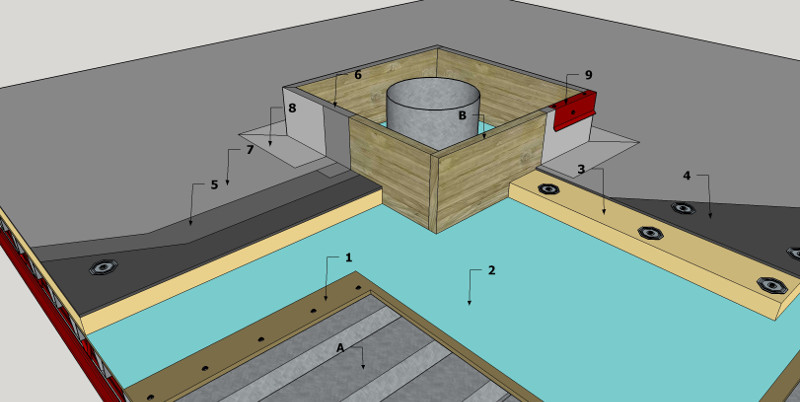
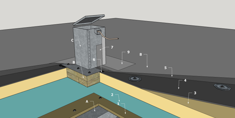
1 MODIFIED BITUMINOUS MEMBRANE: CURB OPENING
1.1 WORK INCLUDED
- (1) Gypsum Board
- Required when insulation is too thin to span flutes of steel decking (See RGC Guarantee Standard A2.5) or when required as thermal barrier by design authority.
- (2) Vapor Retarder
- If required by design authority.
- (3) Insulation
- Mechanically fastened. (See Section 2.2 for accepted materials). (See Section 2.1.1 RGC Guarantee Standard A4.4).
- (4) Overlay Board
- Asphalt adhered or mechanically fastened. Two layers required over heat-sensitive insulation. (See RGC Guarantee Standard C4.1)
- (5) Base Sheet
- Adhered to overlay board using asphalt, cold adhesive, self-adhered, mechanical attachment or torch applied according to manufacturer’s specification and to RGC Guarantee Standards. Torching directly to wood surfaces is not permitted.
- (6) Base Sheet Flashing
- Adhered according to manufacturer’s specifications, using cold adhesive, self-adhered, or torch applied to cover boards, or mechanically attached membrane. Torching directly to wood surfaces is not permitted. (See RGC Guarantee Standards Section 2.1.1, A5.6, and Section 2.1.3, C8.5).
- (7) Cap Sheet
- Applied according to manufacturer’s printed instructions and to RGC Guarantee Standards.
- (8) Cap Sheet Flashing
- Applied according to manufacturer’s printed instructions and to RGC Guarantee Standards to top of curb.
- (9) Metal Flashing
- As required by RGC standards. (See RGC Guarantee Standard A6.9 and A6.10)
1.2 RELATED WORK BY OTHERS
- (A) Acceptable Deck
- (B) Wood Blocking
- Minimum 200 mm (8") in height. (See asphalt adhered or mechanically fastened. Two layers required over heat-sensitive insulation. (See RGC Guarantee Standard A5.6.2) Cant is optional.
NOTE: Refer to RGC Guarantee Standards for additional requirements.
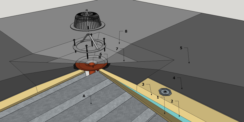
1 MODIFIED BITUMINOUS MEMBRANE: CLAMPING COPPER DRAIN
1.1 WORK INCLUDED
- (1) Gypsum Board
- Required when insulation is too thin to span flutes of steel decking or as thermal barrier when specified by the design authority. (See RGC Guarantee Standard A2.5)
- (2) Vapor Retarder
- If required by design authority.
- (3) Insulation
- Mechanically fastened where possible. (See Section 2.2 for accepted materials and RGC Guarantee Standard A4.4).
- (4) Overlay Board
- Asphalt adhered or mechanically fastened. Two layers required over heat-sensitive insulation. (See RGC Guarantee Standard C4.1)
- (5) Base Sheet
- Adhered to overlay board using asphalt, cold adhesive, self-adhered, mechanical attachment or torch applied according to manufacturer’s specification and to RGC Guarantee Standards. Torching directly to wood surfaces is not permitted.
- (6) Mastic
- Compatible mastic accepted by the membrane manufacturer.
- (7) Base Sheet Flashing
- Adhered according to manufacturer’s specifications and to RGC Guarantee Standards.
- (8) Cap Sheet
- Applied according to manufacturer’s printed instructions and to RGC Guarantee Standards.
1.2 RELATED WORK BY OTHERS
(A) Acceptable Deck (B) Clamping Copper Drain: Primed and mechanically fastened. Installed in bed of compatible mastic.
- NOTE
- Refer to RGC Guarantee Standards for additional requirements.
- Leader size is determined by design authority using the calculation found in the BC Building Code at Appendix P.7.4.10 and Sectionle 7.4.10.11 (Sectionle 7.4.10.10 for gutters) in conjunction with the 15 minute rainfall value from the National Building Code, Appendix C.
1 MODIFIED BITUMINOUS MEMBRANE: TWO PART CABLE FLASHING
1.1 WORK INCLUDED
- (1) Gypsum Overlay Board
- Required when insulation is too thin to span flutes of steel decking or as thermal barrier when specified by the design authority. (See RGC Guarantee Standard A2.5).
- (2) Vapour Retarder
- If required by design authority.
- (3) Insulation
- Mechanically fastened where possible. (See Section 2.2 for accepted materials and RGC Guarantee Standard A4.4).
- (4) Insulation Overlay
- As required. See RGC Guarantee Standard C4.1
- (5) Base Sheet
- Adhered to overlay board using asphalt, cold adhesive, self-adhered, mechanical attachment or torch applied according to manufacturer’s specification and to RGC Guarantee Standards. Torching directly to wood surfaces is not permitted.
- (6) Mastic
- Compatible with membrane
- (7) Base Sheet Flashing
- Adhered according to manufacturer’s specifications, using cold adhesive, self-adhered or torch applied. Must be carried up flashing and terminate under hood flange. Torching directly to wood surfaces is not permitted. (See RGC Guarantee Standards Section 2.1.1, A5.6, and Section 2.1.3, C8.5).
- (8) Cap Sheet
- Applied according to manufacturer’s printed instructions and to RGC Guarantee Standards.
- (9) Cap Sheet Flashing
- Applied according to manufacturer’s printed instructions and to RGC Guarantee Standards. Must be carried up flashing and terminate under hood flange.
1.2 RELATED WORK BY OTHERS
- (A) Acceptable Deck
- (B) Wood Blocking
- (C) Two Piece Flashing
- Assembled around protrusion, laid in bed of compatible mastic on top of base sheet. Mechanically fasten two componentstogether and fasten flange to wood blocking or deck.
NOTE: Refer to RGC Guarantee Standards for additional requirements.
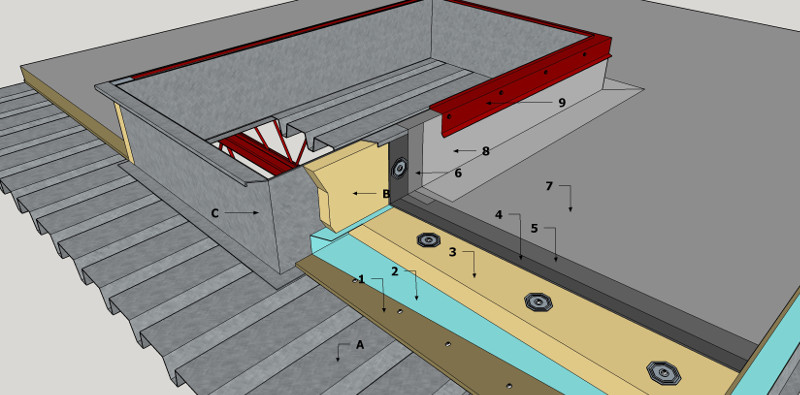
1 MODIFIED BITUMINOUS MEMBRANE: MECHANICAL CURB OPENING
1.1 WORK INCLUDED
- (1) Gypsum Overlay Board
- Required when insulation is too thin to span flutes of steel decking (See RGC Guarantee Standard A2.5) or when required as thermal barrier by design authority.
- (2) Vapour Retarder
- If required by design authority.
- (3) Insulation
- Mechanically fastened where possible. (See Section 2.2 for accepted materials and Guarantee Standard A4.4).
- (4) Insulation Overlay
- As required. See RGC Guarantee Standard C4.1
- (5) Base Sheet
- Adhered to overlay board using asphalt, cold adhesive, self-adhered, mechanical attachment or torch applied according to manufacturer’s specification. Torching directly to wood surfaces is not permitted.
- (6) Base Sheet Flashing
- Adhered according to manufacturer’s specifications, using cold adhesive, hot asphalt, self-adhered or torch applied to cover boards, or mechanically attached membrane. Must be tucked under metal flange and mechanically attached to nailing strip. (See RGC Guarantee Standards Section 2.1.1, A5.6, and Section 2.1.3, C8.5).
- (7) Cap Sheet
- Applied according to manufacturer’s printed instructions and to RGC Guarantee Standards.
- (8) Cap Sheet Flashing
- Applied according to manufacturer’s printed instructions and to RGC Guarantee Standards. Must be tucked under metal flange and mechanically attached to the nailing strip.
- (9) Metal Base Flashing
- Mechanically fasten, standing seam at corners. Full width base flashing optional on flexible membranes. Partial skirt flashing minimum 75 mm (3") required on mechanical curbs that require flashing under metal flange. (See Detail Section 8.3.5).
1.2 RELATED WORK BY OTHERS
- (A) Acceptable Deck
- (B) Rigid Insulation
- (C) Mechanical Curb
- Minimum 200 mm (8") and maximum 300 mm (12") above finished roof surface.
- NOTE
- Some mechanical curbs are designed to allow membrane flashing to be carried up onto metal flange, as illustrated. Install according to manufacturers’ instructions.
- Refer to RGC Guarantee Standards for additional requirements
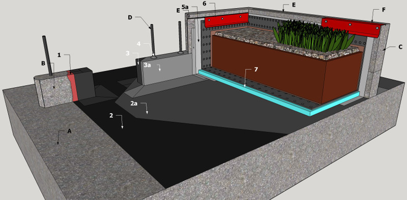
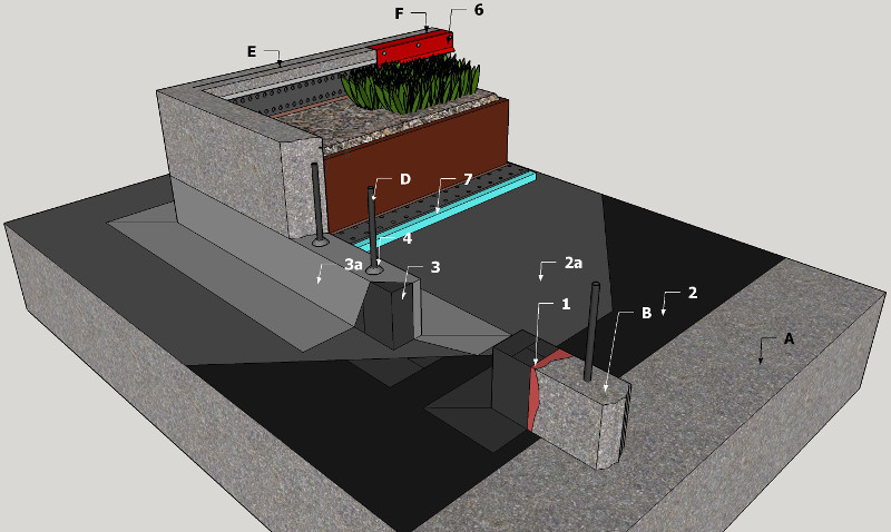
1 MODIFIED BITUMINOUS MEMBRANE: PRE-CURB PLANTER WALL PROTECTED MEMBRANE ROOF ASSEMBLY
1.1 WORK INCLUDED
- (1) Primer
- Application method and coverage rate as approved by Primary Membrane Manufacturer.
- (2) Primary Roof Membrane
- Modified Bituminous base and cap sheet membranes installed as per manufacturer’s published application specifications.
- (3) Pre-Curb (Start-Up Curb) Membrane Flashing
- Modified Bituminous base and cap sheet membrane flashing installed as per manufacturer’s published application specifications.
- (4) Proprietary liquid membrane flashing System
- RGC accepted Liquid Membrane Flashing System(s) (Refer to RPM Section2.2, Section 5.2) or hot melt SBS modified bitumen. Install as per the Manufacturer’s published instructions.
- (5) Inside
- Planter Wall Membrane Flashing: Adhered according to manufacturer’s specifications using cold adhesive, self- adhered or torch applied membrane. Torching directly to wood surfaces is not permitted. Carry membrane flashing plies to reglet termination near top of planter wall (stagger membrane seal minimum 300mm (6”).
- (6) Reglet
- Metal Counter Flashing: As required by RGC Guarantee Standards. (See RGC Guarantee Standard A6.9)
- (7) Plaza Deck Assembly
- Extruded polystyrene insulation and filter mat over primary roof membranes. Concrete pavers placed above pre-curb membrane flashing height, on proprietary pedestals. Note: membrane flashing is not permitted above pre-curb membrane flashing on plaza deck side of planter walls.
1.2 RELATED WORK BY OTHERS
- (A) Acceptable Deck
- Concrete slab shown. Each planter area must have a drain through the roof deck.
- (B) Pre- Curb
- Minimum of 100mm (4”) in height above concrete deck, smooth dry and clean.
- (C) Cast over Concrete Planter Wall
- Form on top of membrane sealed Pre-curbs or Start-up curbs.
- (D) Re-Bar
- Placed a centre of Pre-curb.
- (E) Reglet
- Premanufactured purpose-made reglet cast in concrete wall or saw-cut.
- (F) Alternate Termination
- Horizontal Reglet alternative to premanufactured purpose-made reglet cast in concrete wall or saw-cut on vertical surface of inside planter walls.
NOTE: Refer to RGC Guarantee Standards for additional requirements.

