Difference between revisions of "Fasteners"
Difference between revisions of "Fasteners"
(→Regional Wind Speed) |
(→Regional Wind Speed) |
||
| Line 200: | Line 200: | ||
<hr> | <hr> | ||
| − | |||
| − | |||
| − | [[ | + | |
| − | + | [[Section:B. Essential Elements|<i class="fa fa-chevron-circle-left fa-2x" ></i>Back to ''Essential Elements'']] | |
| + | |||
| + | [[BUR Materials|<i class="fa fa-chevron-circle-right fa-2x" ></i>''BUR Materials'']] | ||
Revision as of 15:49, 27 November 2015
Contents
- 1 General
- 2 Adhesives
- 3 Mechanical Fasteners
- 4 Fastener Corrosion
- 5 Roofing Nails
1 General
Securement of the roof system to the roof deck is necessary to prevent damage caused by wind uplift (possibly resulting in a blow-off) and lateral movement of the roofing materials due to thermal and moisture variations. Traditionally, the roof insulation and roofing are secured to the roof deck by means of mechanical fastening, adhesive, or a combination of both. RGC Guarantee Standards requires mechanical fastening of the insulation wherever practical. Over concrete and other non-nailable decks, or where mechanical fastening is not feasible an adhesive may be used, usually bitumen.
2 Adhesives
In the past, roofing was installed over wood decks using mechanical fasteners. As construction technology progressed, many new types of decks developed bringing with them different securement requirements.
Concrete and other non-nailable decks dictated that an adhesive, usually bitumen, be used to apply the roof insulation and roofing. On sloped roofs where securement is required to prevent slippage, wood nailing strips must be cast into or fixed to the deck to permit mechanical attachment.
On steel decks, the initial use of bitumen as the adhesive has proven to be less successful than adhesion to concrete. Steel deck deflection can result in breaking the adhesive bond between the insulation and the deck. In addition, the use of bitumen may contribute to the fire hazards associated with steel decks.
Several less hazardous adhesives have been developed but have not been entirely successful in achieving adequate adhesion against wind uplift and lateral movement resistance. To properly evaluate an adhesive the design authority must know the strength developed by the adhesive.
Many factors can influence the strength achieved, including substrate characteristics and preparation, bonding area, chemical compatibility of adhesive and insulation and moisture and temperature conditions at time of application. As a result, the industry has developed a large variety of mechanical fasteners designed to secure the roof insulation to steel decks.
3 Mechanical Fasteners
Mechanical fastening to steel decks provides more effective wind uplift resistance and greater horizontal shear resistance than adhesives (thereby decreasing potential membrane splitting). Fastening patterns and rates that have proven to be successful are published in RGC Guarantee Standards and should be enforced as a minimum. In addition to insufficient fasteners, the type of fastener can prove critical. For example, failure may occur from nails with inadequate head size to pull through the roofing felts.
The correct fastener should be specified by the design authority for each component of a roof system.
The design authority should consult with the fastener manufacturer to determine the fastener's pullout strength in specific deck types to determine the number of fasteners required.
Wind uplift has been shown to be greater at the perimeters and therefore fastener requirements vary between field and perimeter areas. In addition, mechanical fastening may be required at the perimeter detail to restrain lateral movement of the membrane.
4 Fastener Corrosion
The design authority should research and establish the correct fastener, deck and roof assembly components in order to prevent the possibility of fastener corrosion. Contributing factors to fastener corrosion may include dissimilar metal contact, excessive building humidity, corrosive chemicals within components of the assembly, or corrosive elements provided within the building envelope etc.
Responsible fastener manufacturers have developed sophisticated fastener coatings and metal alloys to counteract or slow fastener corrosion. These fasteners are usually tested for corrosion resistance through a method called the Kesternich Chamber. This method stipulates that the fastener be exposed to sulphurous acid for a minimum of 15 cycles and show less than 15 percent rust after testing. Proof of successful testing at least gives an indication of corrosion prevention but the designer must still consider the other corrosion contributors discussed.
5 Roofing Nails
Manufacturers of roofing nails that conform to CSA Standard CSA B111, suitable for use in roofing systems include:
- National Nail Inc.
- Simplex Nails
These are available through selected RCABC Associate Members.
5.1 Winduplift
5.1.1 Design Wind Loads
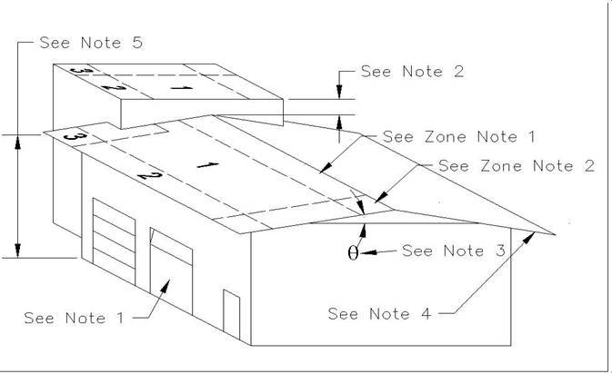
Design Wind Loads are forces caused by wind, which a structure is built to withstand, whether they are negative or positive forces. On the roof the forces are typically negative much like the negative pressure acting on the top of an airplane wing providing lift. Therefore wind acting against the wall of a building passes over the roof exerting uplift on the roofing system. Factors affecting uplift forces are wind speed, building height, roof slope, wall openings, roof overhangs and ground roughness. The roof is divided into three zones: Zone 1, the field; Zone 2, the perimeter; and Zone 3, the corner.
5.1.2 Wind Speed
Designing for wind speed requires specific data. The historical data of weather patterns determines the anticipated wind speeds a structure should be designed to withstand. Wind speed for a wind chart is typically measured at an elevation of 9 m - 11 m (30 - 35 feet) above ground level based on intervals of 50 - 100 years (Mean Recurrence Interval). Section 3.8.5.3 Regional Wind Speed gives a general location of high wind areas in the province of B.C.
5.1.3 Ground Roughness
Also referred to as exposure, this feature has 4 class descriptions, which affect wind load design considerations. General descriptions of these classes from least to greatest loading are:
- Exposure A - Large city center,
- Exposure B - Urban, suburban or wooded area
- Exposure C - Unobstructed areas, in some cases with shoreline
- Exposure D - Flat unobstructed land near open water
For more detailed descriptions see FM 1-28 Design Wind Loads.
5.1.4 Zones
Under wind loading conditions, Zone 1, the field area, has the least uplift, equal to the force against the wall on the windward side of the building. If a 160 kph (100 mph) wind exerts a pressure of 1.9 kPa (40 psf) against the wall, there is 1.9 kPa (40 psf) of uplift (or outward) pressure on the roof in Zone 1. At Zone 2 (perimeter areas), under certain conditions, the uplift can be as much as 1.68 times the field values (about 3.2 kPa [67 psf]). At corner locations (Zone 3) this factor can be as high as 2.53, producing an uplift pressure of about 4.8 kPa (101 psf). If the building has openings in the walls, i.e.: windows, doors or loading bays which allow the interior of the building to be pressurized, these forces can be as high as 4.6 kPa (97 psf) at Zone 2 and 6.1 kPa (127 psf) at Zone 3. Factors for overhangs increase these values again by as much as 1.6 times in some conditions. This emphasizes the need for enhanced fastening zones in mechanically attached roofing systems.
RGC Guarantee Standards fastening standards take into consideration the worst-case scenario for a wind speed of up to 137 kph (85 mph) and building height up to 18 (60’) to meet the FM 1-90 Wind Rating. For an enclosed building, using ground exposure “C”, the uplift design pressure for Zone 1 is 1.1 kg (24 psf). If the building is partially enclosed with an overhang, Zone 1 becomes 1.7 kPa (35 psf), Zone 2 becomes 2.6 kPa (54 psf) and Zone 3 is 3.3 kPa (69 psf). When designing for taller buildings or for greater expected wind speeds an engineer should be consulted to ensure sufficient attachment. As altitude increases, wind speed typically increases but not directly and some geographic locations regularly have high winds. Therefore, the engineer must consider all these variables when calculating the design wind loads.
5.1.5 Fastener Pull-out Strength
Fastener pull-out is the force required to remove the fastener from the substrate without unscrewing. Pull-out test results depend on the deck material, fastener material, shank size and length, and thread pitch and depth. A typical #14 screw designed for insulation attachment (as an example) in a 22 ga. steel deck has a pull-out resistance of 230 kg (507 lb). The total fastener pull-out strength of all fasteners in a sheet must be greater than the total uplift for each sheet being attached. Distribution is also important.
5.1.6 Fastener Distribution
Fasteners must be distributed evenly throughout the sheet material being attached. The actual strength of the material between fasteners is the issue. If a roof requires 1.7 kPa (35 psf) uplift resistance, a 1.2 m x 2.4 m (4’ x 8’ or 32 ft²) sheet of insulation would require a total force of 508 kg (1120 lb) to resist uplift. A single fastener with 522 kg (1150 lb) pull-out strength would cover the uplift force but clearly would not be sufficiently distributed throughout the sheet. In most cases the distribution of fasteners takes precedence over pull-out strength.
5.1.7 Deck Material
Fastener requirements are not the same for all deck materials. As plywood thickness and steel gauge increases, fastener pull-out strength increases, hence less fasteners are required, as shown in the tables at Section 2.1.1.
5.1.8 WIND UPLIFT DESIGN CRITERIA
5.1.8.1 ZONE AREAS
- Field Area:
- Zone 1
- Perimeter Area:
- Zone 2. The area at the edge of the roof. Perimeter width shall be defined as the lesser of 10% of the building width or 40% of the building height, but not less than 2.0 m (7’).
- Corner Area:
- Zone 3. Corner area dimensions shall be equal to perimeter width in both directions and not less than 2.0 m (7’).
5.1.8.2 NOTES
- Wall Openings:
- Contribute to increased wind uplift on roof area. Included in RGC fastener requirements.
- Adjoining Roof Height:
- Where less than 900 mm (3’), design as if one roof. Where 900 mm (3’) or greater, upper roof should be designed as separate roof.
- Roof Slope:
- Wind uplift changes at all Zones as slope changes.
- Overhangs:
- Overhangs increase the wind uplift in some roof locations. Included in RGC fastener requirements.
- Roof Height:
- On slopes under 10° (2’ in 12’ nominal) use eave height for roof height. On slopes 10° (2’ in 12’ nominal) or greater, use mean average roof height (mid-point).
5.1.8.3 ZONE NOTES
- Ridge:
- On slopes over 10° (1:6 or 2" in 12", nominal) the ridge field area should be upgraded to Zone 2 (perimeter).
- Ridge Corner:
- On slopes over 10° (1:6 or 2" in 12", nominal) and on buildings 18 m (60’) high or less ridge perimeter at the corners should be upgraded to Zone 3 (corner).
NOTE: Refer to RGC Guarantee Standards for additional requirements.
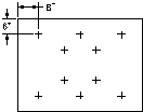
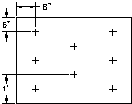
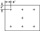
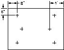
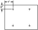
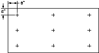
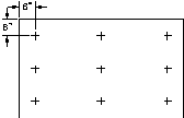
5.1.9 FASTENER PATTERNS: VARIOUS BOARD SIZES
| 4'x8' | 4'x6' | 4'x4' |
|---|---|---|
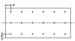 18 Fasteners |
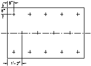 14 Fasteners |
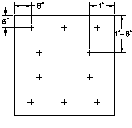 10 Fasteners |
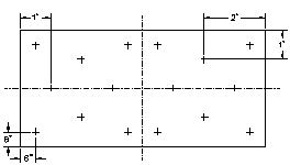 16 Fasteners |
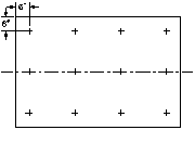 12 Fasteners |
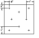 8 Fasteners |
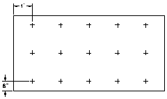 15 Fasteners |
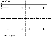 10 Fasteners |
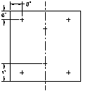 6 Fasteners |
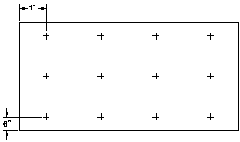 12 Fasteners |
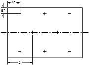 8 Fasteners |
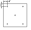 5 Fasteners |
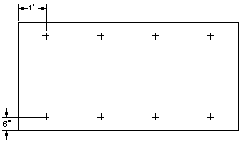 8 Fasteners |
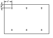 6 Fasteners |
NOTE:
- Fastener locations are for optimum uplift resistance. Fasteners may be located within 50 mm (2") of position shown in diagrams in any direction.
- For acceptable insulation fasteners see RGC Guarantee Standard A4.4
NOTE:
- Fastener locations are for optimum uplift resistance. Fasteners may be located within 50 mm (2") of position shown in diagrams in any direction.
- For acceptable insulation fasteners see RGC Guarantee Standard A4.4
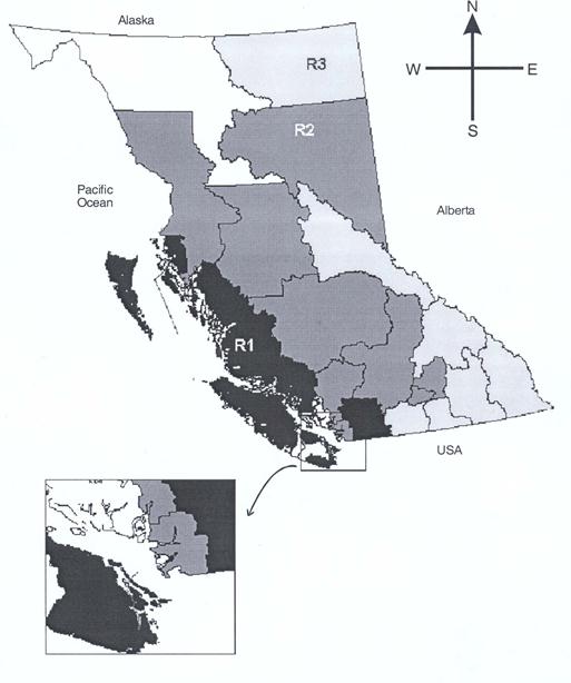
5.1.10 Regional Wind Speed
The province of British Columbia is divided into three regions:
Region 1 - High wind region
Region 2 - Moderate wind region
Region 3 - Low wind region
Note:
- Region 1 is located near the coast while most of Region 3 is located at the inland area.

