Roof Maintenance
Roof Maintenance
1 Introduction
This section has been reprinted with the kind permission of:
- The Roofing Industry Educational Institute (RIEI)
- 14 Inverness Drive East
- Building H, Suite 110
- Englewood, Colorado 80112-5608
The purpose of this manual is to provide the reader with guidelines for establishing and conducting a roof maintenance program.
- Why Does a Roof Need Maintenance?
A roof system is exposed to all manner of chemical and physical stress. The long-term effects of these forces are called “normal aging”. In reality, small isolated problems caused through abuse, stress concentration, error or other factors result in shortened lifespan. These small problems, if undetected, escalate over time until they are extensive and more expensive to resolve.
The most important reason for establishing a program of regular roof maintenance inspection is to protect the owner’s investment. A properly executed maintenance program will not only add years to the life of the roof, it will also detect minor problems before damage is widespread and will avoid interruption of the internal functions of the building.
A smooth-functioning maintenance program will allow capital to be requested on an orderly basis, so that, as each roof membrane finally reaches the end of its life cycle and is no longer economical to maintain, it can be replaced or recovered in the best possible weather. Thus, a good maintenance program is in operation from the time a built-up roof is specified until the time it is replaced.
2 Establishing A Maintenance Program
A planned maintenance program is simply a program of scheduled inspection and corrective action. The best time to plan for roof maintenance is at the time the roof is first designed and installed.
At that time, an HISTORICAL FILE should be compiled and turned over to the owner. The following items should be included in the file:
- As-built BUR specification(s) and applicable addenda.
- Roof plan(s) showing location of all penetrations and rooftop equipment.
- As-built drawings of construction details directly related to the roofing system, such as flashings, deck, etc.
- Minutes of pre-job conference, including list of those present.
- Reports by job inspector during applications including weather condition, materials used, code numbers on packaging, identifying areas completed each day (including photos), etc.
- Materials manufacturer specifications and brochures for each component (approved submittals).
- All correspondence or notes between parties involved with the installation of the roof.
- Roof bonds or guarantees from manufacturer and / or roofing contractor.
- Report of each subsequent maintenance inspection performed (including photos).
- Reports of any previous problems and corrective action taken.
- Record of any changes made to or on roof surface or substrate and copies of letters notifying roofing manufacturer of such changes.
- Record of new mechanical equipment installations and date.
The historical file should be supplemented by interviewing key personnel at the building site.
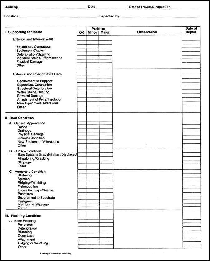
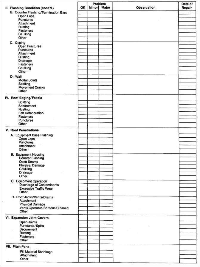
The second step is to conduct THE ROOF SURVEY. This is covered in detail elsewhere in this manual. Checklists and a building plan help in making a thorough survey. This manual is set up in the same order as the RoofStar Guarantee Program (RIEI) checklists. Regular inspections should be made by competent personnel at least twice a year, in the Spring and the Fall. The Spring inspection permits observation of possible Winter damage and allows repairs to be made in the best possible weather. A Fall inspection allows for observations to be made in preparation for the oncoming Winter. Extra inspections should be made after major storms or after any construction activity that could affect the roof. Non-destructive roof surveys might be combined with the visual techniques described in this manual, either on a regular basis or when water penetration is suspected.
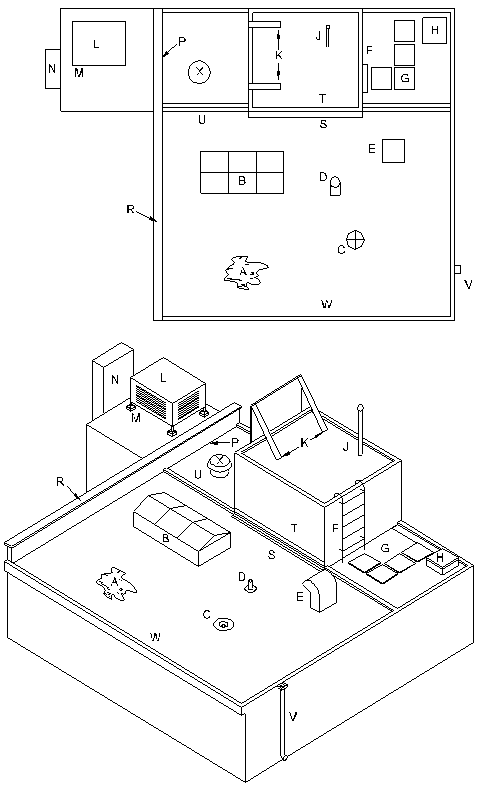
When surveys are completed, all the roof areas should be categorized as to their condition, and where necessary, repair procedures and priorities established. Repair programs can then be conducted in the best weather, with capital allocated based upon priorities. The priorities can be clearly marked on a copy of the roof plan (see next page for example), and updated as work progresses.
|
A - Ponded Water B - Skylight C - Roof Drain D - Vent Pipe E - Vent or Fan F - Ladder G - Walkway H - Hatch J - Flag Pole K - Sign Support L - Air Conditioning Unit M - Pitch Pan N - Chimney & Flashing P - Parapet or Fire Wall R - Coping S - Base Flashing T - Cap Flashing U - Expansion Joint Cover V - Down Spout & Leader W - Fascia & Gravel Stop X - Roof Vent |
3 Roof Inspection
Many of the remarks in this section pertain to bituminous built-up roofs. However, data is also included on flexible membrane (“non-conventional”) systems as applicable.
3.1 Inspection Materials
Basic material (for visual inspections)
- Clipboard, latest roof plan, inspection forms, ruler and coloured pencil or pen
- Camera and film
- Aerosol can of bright spray paint or crayons
- Sharp knife
- Measuring tape
- Pocket whisk broom
- Flashlight
- Supplemental materials (for cleaning and minor patching)
- A can of roof mastic (for bituminous roofs)
- Small can of adhesive, solvent, brushes, or other patching equipment recommended for elasto / plastic roofing
- Pointed trowel for mastic or brush for adhesive
- Screwdriver (to open pails)
- Stiff wire brush to clean surfaces of dirt or rust
- Carrying bag with sturdy handles to hoist and carry tools
- Rope, with safety clip, to hoist materials
- Reinforcement fabric, i.e., jute, woven treated glass mesh, narrow roll of roofing felt, uncured elastomeric sheeting for elastomeric membranes, appropriate sheeting for other products.
- Scissors to cut reinforcements
- Straight claw hammer, spud bar or 35 mm (1-1/2") chisel to remove aggregate
- Small can of primer and brush
- Work gloves Additional materials (when roof cuts are planned)
- Large plastic bags (i.e. trash bags), masking tape, labels
- Wider rolls of patching materials
- Insulation to replace any wet materials discovered in cuts
- Additional mastic of correct type
- Small jar to run solvent test on bitumens
- Mineral spirits for clean-up
- Delmhorst meter for moisture probes
- Templates of required sizes
- Masonry saw if roof has aggregate surface
3.2 Conducting a Roof Inspection Using the RoofStar Guarantee Program (RIEI) Checklist
During the inspection, every component of the roofing system should be closely checked. Signs of deterioration should be noted, as well as rooftop traffic patterns, signs of poor drainage and collections of debris.
- Before the roof inspection is conducted, a visual inspection should be made of the structure itself. Exterior walls frequently indicate signs of movement which may relate to roof problems. Water stains might suggest problems with fascia / gravel stops, flashings, copings and / or in colder climates, air leakage.
- When the interior deck is visible, indications of the integrity of the deck are important. Signs of rust or spalling may indicate serious degradation of the system.
- Note the type of deck and if it appears to be lying flat over supporting members with no evidence of detachment.
- Has the deck shrunk, buckled, cracked, warped or distorted
- If deck is of precast units, are there any indications that units have shifted, opening cracks at some joints
- Has the type of occupancy changed (to higher humidity, etc.) since the roof system was designed
- Check to be sure horizontal runs of water and drain pipe are insulated, particularly in false ceiling areas.
- Check any water stains on ceilings, piping, ducts or supporting members as well as underside of deck, to attempt to isolate potential areas of leaking.
- Check for any physical damage.
- Note any alterations or installation of new equipment which either penetrates or could overload the roof deck.
3.3 Rooftop Inspection
Before completing the (RIEI) checklist below, refer to “as-built” specifications on the previous inspection report. Determine the composition of the roofing system, i.e., bituminous, elastomeric, inverted, etc. Is the membrane the original one or is it a recover Are there patches or problem areas
- General Impression
- First impressions of the roof appearance should be written down. Collections of debris, clogged drains, ponded water, etc. may suggest changes in routine (housekeeping) procedures. Vast amounts of equipment, stacks, vents and other penetrations might suggest a study to see if the equipment could be entirely removed. Heavy traffic on the roof may require protective traffic pads.
- Orientation of the roof plan
- Note North on all plans. It is generally helpful to break the roof down into smaller areas for note taking. These might by alphanumeric such as Roof Area A-1, A-2, etc., or by function such as “Boiler Room”. Note building height.
- Note
- When entirely different roof systems are used, i.e., folded plate steep roof over gymnasium compared to flat roof deck elsewhere, a completely different inspection file is suggested.
- Surface Condition
- Examine surface for compliance with original specifications. Ballasted roofs rely on aggregate for wind protection and securement. It may be desirable to estimate depth of surfacing and check weight. Severely eroded corners of roof might require heavier stones or pavers, especially if evidence of lifting or wrinkling is found.
Bare spots on bituminous roofs may be due to wind sweeping, flow of flood-coat, blistering, etc. On organic membranes, these bare spots can seriously affect long term performance. Inorganic systems of asbestos or glass fibre may not require immediate protection, but should be recoated during periodic maintenance.
Good photographs of common roof surface problems can be found in several available maintenance publications.
- DEFECTS IN BUILT-UP BITUMINOUS ROOFING MEMBRANES
| Defect | Probable Causes |
|---|---|
| Blisters between layers of felt | Expansion in sunny weather of entrapped air or water in areas of poor adhesion |
| Blisters between felt membrane and substrate | Expansion in sunny weather of entrapped air or water, usually over decks with concrete fills or with wet insulation. |
| Cracking or breaking | Breaks in unsupported felt. Cracking of blisters or ridges by traffic. Breaks at sharp bends in felt. |
| Tensile splits | Stress concentrations due to inadequate attachment. Flexure at moving joints, fatigue, several other causes. |
| Ridging or buckling | Movement of the felts, deck or substrate under moisture or thermal affects, causing long ripple ridges especially where felt is not well bonded; often over insulation or deck joints or at lap of base sheet. |
| Lifting at laps (fishmouths) | Poor adhesion initially due to wrinkled felt or workmanship, or pulling as a result of blister or ridging formation. |
| Felt penetrating top pour and gravel at laps | Poor workmanship initially resulting in poor adhesion. Curling of felt edges when left exposed too long during construction. |
3.4 Flashings
Terminations and connections to a roof system require careful inspection.
Base Flashings, such as at joints where a roof membrane is terminated at a vertical wall, are very susceptible to concentrated stress or puncture. Right angle bends, where cant strips have been omitted, invariably result in fatigue failure.
Loose-laid systems may require special attachment techniques, as the terminations are key anchorage points for the entire membrane.
| Defect | Probable Causes |
|---|---|
| Flashing failures | Inadequate allowance for movement. Inadequate fixing intoreglets or inadequate use of nailers. |
| Poor adhesion or inadequate protection of stripping felts. | |
| Movement at roof drains or vent pipes. | |
| Damage to coping at parapets and expansion joints. | |
| Loss of mastic or damage to pitch pans. | |
| Inadequate height. | |
| No cant strip. | |
| Ponding of water. | |
| Shrinking of roofing membrane. | |
| Counter-Flashings are subjected to thermal and wind stresses. Many problems will relate to movement, flexure or vibration. | |
| Loose at mortar joint | Movement of wall or metal. |
| Disintegration of supporting mortar. | |
| Insufficient depth of metal. | |
| Open Laps | Movement of wall. Thermal expansion with inadequate restraint. |
| Fastener Popping | Fastener not properly designed or installed. |
| Loose at reglet | Inadequate design of receiver. |
Coping problems are similar to counter-flashings in nature. Copings should be designed to shed water away from joints in the wall or flashings. Joints require careful inspection for porosity, disintegration, etc.
Walls -- Mortar in masonry units, fasteners and laps in metal sidewalls, and other joints should be carefully inspected. Air leakage may show up as spalling or efflorescence (white salt deposits) on wall surfaces. The air leakage may be caused by internal air pressure such as chimney effects and / or missing vapour seals in the wall or roof system. Spalling and salt deposit may also be due to porous masonry or leaking copings.
3.5 Roof Edging / Fascia
Thermal or wind-induced movements put great stress on the contact points between metal and bituminous surfaces. Laps or metal edging, even when carefully stripped in, will ultimately overstress the waterproofing detail.
Current flashing details reflect this dilemma by raising the metal out of the reaches of ponded water. On inspection of existing roofs each metal lap must be inspected for splitting of the bituminous stripping. Old patches may need to be removed and surfaces cleaned before repairs can succeed.
Some elastomeric systems carry the membrane under the metal and down the fascia. Many thermoplastic systems will leave a gap between the metal pieces. This is capped with a plastic sheet. Refer to the historical and as-built file to determine what materials were used and for specified edge details. Do not contaminate plastic / elastomeric sheets with bituminous patches.
3.6 Roof Penetrations
Every penetration in a roof membrane threatens its integrity. Check to determine if existing equipment is absolutely necessary, and remove when possible.
Current practice suggests wood curbs be used to raise equipment above the water level. Refer to industry manuals for excellent flashing details.
3.7 Flanges
Flanges on expansion joint covers should also be raised above water level. Existing flanges are subject to many of the same problems as roof edging. Splices of joint sections may work loose. Again, avoid bituminous contamination and use appropriate elastomeric repair materials. Check the historical file for “as-built” expansion joint covers.
3.8 Pitch pans
Pitch pans are no longer recommended (see alternates in industry manuals). Existing pans are troublesome as the filler shrinks with age. Heat, oxidation, rust, scaling paint or vibration of the pipe also breaks the seal. The level of filler should be checked at every inspection. Pipe saddles, guy wires, and other “abrasive” penetrations should be affixed to raised (and properly flashed) curbs. It is sometimes best to try to install a skirt or cone to the pipe or penetrations which would completely cover the pan.
4 Repair Techniques
Repairs are listed as Emergency, Maintenance (prior to failure), and Recover / Replacement.
4.1 Emergency Repairs
The best time to prepare for emergency repairs is before they occur. This suggests keeping a supply of basic repair materials on hand. Special leak-plugging chemicals such as expanding bentonite might also be considered.
Emergencies, by definition, require quick action, usually in adverse weather conditions. Severe weather conditions are dangerous conditions, both on the roof, as well as inside. Electricity and water are a hazardous combination. Protect occupants by closing-off areas that are endangered or shut off electrical service, if necessary.
- Suggested Tools and Equipment
- Satchel to haul tools
- Treated woven glass or burlap (for bituminous systems)
- Bituminous mastic (appropriate for roof type). (Some “wet-patch” mastics may be helpful.)
- Adhesive and narrow rolls of elastomeric / plastic membrane Suggested
- Tool Kit
- Screwdriver, sharp knife, scissor, straight claw hammer
- Trowel for mastics, brush for adhesives
- Dry rags
- Large-headed nails for flashing failures
- Push broom
4.2 Roof Top Procedures
Safety first! Two men should work together. Before stepping onto the roof, check for fallen electrical lines or other dangerous situations. If the roof is so heavily loaded with water, snow or ice that the deck could collapse, notify the occupants to evacuate the building.
Water may back up into flashings, pitch pockets, or wall surfaces if the membrane cannot drain freely. Examine drains first, and clear the strainers. Do not remove the strainers to reach into a drainpipe, as the sudden cleaning may cause dangerous suction.
Leaks sometimes are associated with punctures from wind-toppled equipment. Look for signs of missing hatch covers, loose guy wires, or other clues to punctures.
Use brooms, squeegee, snow shovel, pumps, or siphons when necessary to lower water level. As water level drops, have occupant observe interior leaks. When they slow down, the puncture may be at the perimeter of that ponded area. (Shovels will probably damage surface of membrane, and should be allowed only when snow build-up is great).
Wind torn or displaced roofing requires battens, sand bags, concrete blocks or other emergency steps to protect ever widening damage. On steel or nailable decks, wood batten strips can be fastened directly through the membrane. Tarps or other covers may have to be applied and ballasted to seal areas where the membrane has been lost. Look for missing fascia metal, displaced copings, or other perimeter damage as wind effects usually are most severe at the corners and perimeters of roof areas.
4.3 Wet Condition Repairs
Obviously these are hurry-up situations and repairs should be regarded as temporary only. Permanent, durable repairs should be completed as soon as conditions allow.
Dry out the surface as much as possible. Even “wet-patch” materials have a better chance of success if surface water is removed. If necessary, dam off water flow to repair area by bedding 50 mm x 100 mm (2" x 4") nominal in plastic cement or use sand, sandbags, portland cement, mortar mix, or lime, etc.
Wipe clean with rags, dry with propane torch, compressed air, fans, hot air guns, etc. (Caution in using electrical devices in wet area). Chip or brush debris or gravel back at least 100 mm (4") to either side of damaged area to receive patch (bituminous roofs). Wire brush elastomeric surfaces to remove oxidized layer, wipe with ether or acetone to remove surface moisture and apply contact adhesive. On thermoplastic membranes, clean and use heat welding rather than solvent welding to help evaporate water. Do not attempt to froth urethane patches in wet weather; plug with bituminous material until weather allows proper repair. With all products of elastoplastic systems (flexible membrane), check with materials manufacturer to insure compatibility.
After the emergency is under control, record the location of the temporary repairs and schedule permanent repairs as soon as possible. In the event severe weather persists for weeks, the patches may have to be checked on a frequent basis and redone as necessary to protect the building.
4.4 Basic Repairs
Each category of the roofing system will have some basic repair techniques that serve well in a variety of conditions:
| Category | Basic Materials |
| Bituminous Membranes | Bitumen-based primer, mastic, fabric, coatings. |
| Thermoplastic (PVC) | Solvent for welding, same film as membrane, caulk for lap edges. |
| Thermoplastic (Modified Bitumen) | Mastic, same film as membrane, heat welding torch. |
| Elastomeric Sheets | Contact adhesive, flashing adhesive, uncured film (note both mastic and film will cure with age, use fresh material). |
| Liquid-applied Elastomerics | Primer, correct coatings (caution -- use fresh material). |
| Sprayed-on Polyurethane | Froth pack as suggested by manufacturer; coating system and primer identical to in-place system (i.e. Hypalon, silicone, acrylic). Granules to embed in coating. Caulk to fill small coating perforations. |
Bituminous Membranes -- Basic Repair Techniques
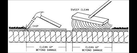
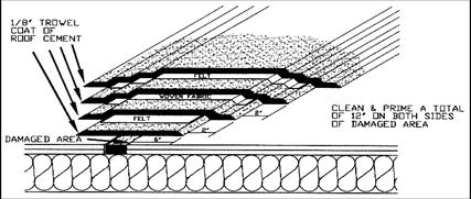
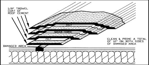
1 Clean and dry surfaces approximately 300 mm (12") to either side of damaged area. On aggregate-surfaced roofs, the surfacing should be chipped away down to the felts.
12" = 300 mm
2 Prepare surfaces with brush application of bituminous primer. This penetrates loose dust, etc. and promotes adhesion.
3 Apply mastic.
4 Embed recommended patching fabric. Each layer should extend 50 mm (2") further onto existing membrane.
1/8" = 3 mm
2" = 50 mm
6" = 150 mm
12" = 300 mm
- Thermoplastic - (PVC) Film - Basic Repair Technique
A. To repair membrane:
- 1 Clean, wipe with solvent if necessary to remove contaminants.
- 2 Apply solvent to clean, dry surfaces only, in dry weather. Alternate system uses heat welding which may be more reliable in damp or cold weather.
- 3 Embed new film immediately. After solvent evaporates / film cools, inspect carefully with blunt tool to be certain edges are sealed.
- 4 Use heat-gun and roller to seal any loose edges.
- 5 Caulk all exposed edges with appropriate caulk.
B. To repair special coated metal (Base Flashings):
- 1 Salvage original metal with PVC coating when possible. Re-secure with screws, nails, etc. as necessary.
- 2 Clean and wipe as above.
- 3 Follow steps for film above.
- 4 When new metal is required for above repairs or for new installations, purchase special coated metal from film supplier only. Do not use galvanized, etc.
- Thermoplastic (Modified Bituminous) Film - Basic Repair Technique
- 1 Remove damaged material, clean surfaces to be bonded.
- 2 Prime with bituminous primer.
- 3 Apply special mastic where recommended. In some cases, ordinary bituminous mastic is acceptable. Refer to literature for correct materials and reinforcements.
- 4 Many systems can be “torched” with a propane torch. Caution -- use appropriate equipment. Do not “experiment” on the roof. Keep fire extinguisher handy. Technique requires experience to “flux” old and new materials together, followed by pressure on trowel, spatula, or flat edge of knife to ensure adhesion. Too much heat may melt reinforcement.
- 5 Resurface as required. Some materials have factory applied granules, foil etc. Others may have gravel embedded in mastic, loose ballast, or conventional roof coatings.
- Elastomeric (Cured-Vulcanized) Sheets - Basic Repair Technique
- 1 Clean surfaces.
- 2 Abrasion with wire brush, sandpaper, etc. may be necessary to roughen surface and remove surface oxidation.
- 3 Use primer where specified.
- 4 Apply “contact” cement (proprietary adhesive) to both surfaces to be bonded. Allow to dry until light finger touch is tacky but does not transfer to finger.
- 5 Carefully embed new film, starting at one side only, so all air is expelled in front of film.
- 6 Press firmly, roll with hard roller.
- 7 Inspect laps and reseal as needed.
- 8 Caulk edges with elastomeric caulking.
- 9 Resurface to match rest of system.
- Elastomeric (Liquid-Applied) Systems - Basic Repair Technique
- 1 Clean surfaces, abrade to remove oxidation.
- 2 Apply brush-coat of base material (e.g. in Neoprene-Hypalon system, base coat is black neoprene).
- 3 While tacky, lay repair fabric into base coat and firmly embed. Apply more base coat to thoroughly impregnate fabric. Allow to dry.
- 4 Apply additional coats of base and colour coat until mil thickness matches original membrane.
5 Embed granules or grit into final coat to match rest of system.
- Sprayed-on Polyurethane (and coating system) - Basic Repair Technique
- 1 Clean surfaces, remove damaged material.
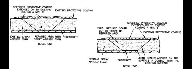
- 2 Trim exposed foam in fracture to obtain clean foam surface to depth of penetration. Slices of 3 mm to 6 mm (1/8" to 1/4") are adequate to provide suitable foam surface for patch. Bevel cut edge at approximately 45° angle around perimeter of opening to depth of penetration.
- 3 Brush back loose granules and abrade coating around penetration.
- 4 Use Froth Pack, or take two cups, one each marked A and B. Fill A to 40% of volume with the isocyanurate component and cup B to 40% of volume with the polyol component.
- 5 Gradually pour contents of cup A into cup B while stirring with wooden tongue depressor or spatula. Continue stirring the combined materials for approximately 30-40 seconds or until mixture begins to show a colour change which indicates incipient foaming.
- 6 Gradually pour foaming mixture into prepared areas as follows: Begin by pouring material onto bevelled cut foam edge in order to wet out as completely as possible, then distribute remaining material evenly over bottom of the penetration or repair area.
- 7 Permit the foam to rise and set. Allow in-place foam to cure for a minimum of 1/2 hour.
- 8 If repair area is underfilled, a second or third pour may be required to completely fill the void.
- NOTE -- With experience, it will be found that quantities of the foam system can be varied to match size of repair.
- 9 If second or third pour is required, pour(s) can be made as soon as foam is tack free (4-5 minutes) without waiting for 1/2 hour cure period.
- 10 Alternative: Install rigid 1.1 kg to 1.4 kg (2-1/2 to 3 lb) density urethane foam board, cut to shape in the prepared area. Embed in sealant applied on the surfaces to come in contact with the existing spray foam and substrate (See detail two).
- 11 Once foam in filled void is cured, trim away excess foam with serrated knife, saw or grinder to level of adjacent roof. Remove all foam dust and / or bits prior to application of coating.
- 12 Following above steps, brush coats of protective coating to be used can be applied for completion of the repair.
- It is recommended that a total of 0.65 mm to 2 mm (25 to 80 mils) wet coating be brush-applied over the repaired area, using a two-coat procedure. A minimum of 4-6 hours drying time should be utilized between coats.
- Further, the same drying time should be permitted after application of the final coat prior to subjecting the repaired area to foot traffic.
4.5 Specific Repairs
4.5.1 Surface Conditions
- A. (1) Bare Spots: Gravel Surfaced Bituminous Roofs
- Description:
- Loss of aggregate, aggregate not bonded to bitumen, loss of bitumen, felts exposed to weather.
- Problems:
- Loss of protection allows rapid deterioration of bitumen and felts. Exposed membrane may absorb moisture and degrade through freeze / thaw or wet / dry cycles.
- Repair Procedures:
- Remove loose aggregate, dirt, and debris.
- Repair all damage before surface treatment.
- Trim and discard all loose or curled felts.
- Apply cold-process recoating / resaturant and re-embed gravel to match rest of roof.
OR
Prime with asphalt primer and re-pour with appropriate hot bitumen for slope and climate.
OR
If bare spots are very small, such as crowns of ridges or tops of blisters, prime, apply roof mastic and re-embed loose gravel.
- (2) Bare Spots: Smooth Surfaced Bituminous Roofs
- Description:
- Loss of coating, erosion due to water flow, normal weathering.
- Problems:
- Smooth roofs will normally consist of asbestos or glass based membranes, and in this case the natural weathering of the coating is not a major defect, as long as roof area is free of ponded water.
- Repair Procedures:
- Re-coating will normally consist of light applications of emulsions, cut-back coatings, aluminium roof coatings, etc.
- B. Eroded or Abraded Bituminous Surface
- Description:
- Traffic patterns, wind scoured corners, water washed bare spots, or loss of bitumen from chemical / physical attack
4.6 Problems
- Loss of protection as above.
- Repair Procedures:
- Traffic patterns: access to roof areas should be limited. Foot traffic can be directed by chains or handrails. Membrane can be protected by asphalt planks, wood walkways, etc.
- Wind scoured corners may require double pour and gravel technique, using hot bitumen. re-coatings / re-saturants following manufacturer's instructions.
OR
- Use coarse rock (normally 38 mm [1-1/2"]) embedded in fresh applications of bitumen or mastic.
- Water Washing - use splash pans to reduce velocity of water. Divert condensate from air conditioners, etc. to drains or locate new drains to pick up water flow. Re-embed surfacings as for Bare Spots, A(1) and A(2) above.
- C. Loss of Gravel Ballast on Loose-Laid Systems
- Description:
- Displacement of ballast due to wind, erosion or billowing of membrane. Sometimes moved intentionally by workman.
- Problems:
- Loss of ultra-violet, fire, and wind uplift protection.
- Repair Procedures:
- Replace stones with heavier application to reduce lifting; OR
- Use coarser stones; OR
- Use concrete pavers in localized locations; OR
- Use concrete pavers to delineate walkways, to keep gravel back from drains, and to provide work platforms at rooftop equipment. Do not use asphalt walkways on PVC membranes.
- D. Loss of Ballast - Protected Membrane Roof Systems
- Description:
- Floating or physical displacement of insulation may cause (or result from) displacement of ballast.
- Problems:
- Ballast in PMR system not only protects insulation from fire, wind and sunlight but keeps insulation from floating due to buoyancy in an intense rainstorm.
- Repair Procedures:
- First determine the cause for flotation. If drains have become non-functional, they must be properly repaired to assure good drainage.
- If insufficient ballast was installed, add additional ballast to bring weight up to specification.
- If boards have been poorly adhered in an adhered specification, they may have to be re-adhered. Caution: Do not allow solvent based mastics to be used as these will damage polystyrene foam. The membrane must be clean and dry if hot bitumen is to be used as an adhesive. Allow hot bitumen to cool somewhat before re-embedding polystyrene.
- Alternative: loosely lay the affected boards and overlay them with a non-woven synthetic fibre mat, which should extend 600 mm to 900 mm (2' to 3') beyond the loose boards in all directions. The mat application helps distribute the weight of the ballast to restrain the loose, floated boards.
- Where stone has been misplaced due to foot traffic, use pavers as in “C” above.
- E. Alligatoring / Cracking - (Bituminous Systems):
- Description:
- Shrinkage of the surface of bitumen results in a “mud-cracking” pattern having the scaly look of an alligator's hide. The pattern is most pronounced in thick applications of exposed bitumen, such as where extra material has flowed out of laps in felt or flashing applications.
- Problems:
- As surface continues to shrink, cracks develop down to depth of felts and may stress-crack the membrane in cold weather. Channels hold water which penetrates membrane.
- Repair Procedures: Smooth Asphalt Roofing
- Light checking / crazing: Clean surface and remove “blobs” of thick bitumen. Apply thin coat of asphalt primer (less than 0.5 L / sq.m (1 gal / square), and allow to dry. Apply clay-stabilized asphalt emulsion, making sure all fissures are filled.
- Heavy checking / cracking to felt depth: Clean and prime as above. Apply emulsion as above, but while it is still wet, embed resin or bitumen treated porous glass mat or glass fabric. Lap fabric 50 mm (2"). Press gently to allow emulsion to totally wet fabric. Apply additional emulsion. Non-woven synthetic mats may be substituted for the treated glass products. Prime as above.
- Apply chopped glass roving simultaneously with emulsion. Apply using equipment designed for this purpose.
- NOTE: Do not add additional hot asphalt to an alligatored roof surface. This increases the coefficient of thermal expansion of the bituminous film and makes cracking even more severe. Slight exposure of glass or asbestos felts is usually not serious, and is preferred to heavy bituminous coatings.
- F. Surface Slippage - (Flow of Bitumen and Aggregate)
- Description:
- Liquefaction of flood coat, with flow towards drains and other low spots. Usually occurs in hot weather. Flow of excess bitumen from laps of felt.
- Problems:
- Clogging of drains; loss of protection where aggregate and flood coat are lost.
- Repair Procedures:
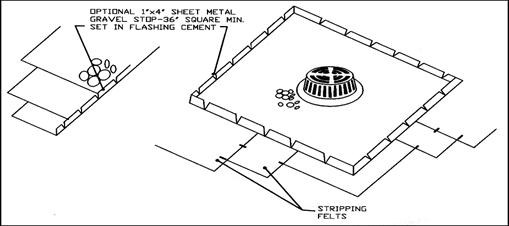
- Clear drains, place extra gravel
guard, etc. around drains to hold surfacing back. Flow gradually slows with time and surface hardening; therefore, an application of a heavy coat of white-wash or other reflective coating each Spring will usually suffice for a couple of years. All lost aggregate should be replaced prior to coating.
1" = 25 mm
4" = 100 mm
36" = 915 mm
- G. Loss of Coating System - (Foamed Polyurethane Systems)
- Description:
- Erosion due to natural weathering, abrasion, excessive water flow; reveals brownish-yellow colour of polyurethane foam underneath. Problems:
- Polyurethane foam is vulnerable to ultraviolet attack and weather degradation. Roof may not leak, but loss of insulation value worsens with time.
- Repair Procedures:
- Follow instructions of coating manufacturer. Steps generally include surface cleaning and abrasion to remove “chalk”, priming, refoaming when necessary, application of new coatings and surface texture if applicable.
4.6.1 Membrane Condition
- A. Blistering (Bituminous Membranes)
- Description:
- Raised, enclosed swelling in the roof surface; spongy feel when pressed. May occur between layers of felt or between roof membrane and substrate. Usually associated with skips or voids between two impermeable surfaces. The entrapped air contains moisture which expands as the temperatures rise, resulting in sufficient pressure to push the felts apart.
- Problems:
- Bare spots due to surface flow are vulnerable (see Bare Spots). Blisters may be broken by foot traffic or hail, resulting in punctures (see Punctures). Blisters may be so large as to affect drainage, causing ponding. Blisters may grow so large that they pull laps apart, resulting in leakage.
- Repair Procedures:
- Small (less than a foot in diameter), unbroken blisters are best left alone. Blisters holding pressure do not leak water. Do not step on or intentionally puncture blisters. Note the condition on inspection forms, and mark some of the blisters with paint, so it can be determined whether they are getting worse with time.
- Bare spots should be treated (see Surface Conditions - Bare Spots, 11.1.3 page 6).
- When blister repairs must be made, the following steps can be followed:
- (1) Remove entire blister to point at edges where remaining felts are well-adhered.
- (2) Let remaining surface dry thoroughly.
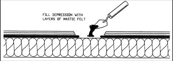
- (3) Fill depression to level of surface of roof membrane using fitted felts adhered with bituminous mastic.
- (4) Trowel mastic smoothly over patch or leave area slightly raised.
- (5) Complete the repair following the basic repair procedures presented previously.
1/8" = 3 mm
2" = 50 mm
6" = 150 mm
12" = 300 m
- If more than a few blisters need to be repaired, hot bituminous repairs and patches should be considered.
- On aggregate-surfaced roofs, removal of all aggregate around perimeter of patch is very important. This “chipping” can best be done in cool weather or early in the morning. However, blisters should be repaired in the warm part of the day when felts are ductile and less likely to be harmed by foot traffic and “walking-in”.
- Some maintenance manuals recommend making “X-cut” blister repairs. In this technique, the corners of the cut are peeled back (in warm weather), the interior of the blister is allowed to dry, mastic is worked into the cavity, the “ears” of the membrane are pulled back into place, and the mastic is “walked-in” so that it completely fills the cavity and extrudes out the cut edges. The “X-cut” is then patched or new felts are applied to completely cover the cut area. The problem with this technique is that you must be sure there are no remaining voids at the back edges of the “ears”, and that all water has been removed.
- B. Blistering in Cap Sheet Roofing or 2-Ply Modified Bituminous Roof Systems
- Description:
- Spongy raised area as in “A”.
- Problems:
- More vulnerable to puncture, hail damage, etc.
- Repair Procedures:
- If the blisters are low in profile, the “X-cut” technique is sometimes used, but more reliable repairs can be achieved by removing the blister, filling in and patching. In the modified bituminous systems, repairs can be made with cold mastic or in some cases by propane torch or heat gun. Refer to the historical file for information on the system being worked on.
- C. Splitting (Bituminous Roofs)
- Description:
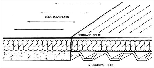
- Long cracks in roof membrane. Direction of split may be parallel to felts or insulation joints, indicating tensile failure due to concentrated stress. Sometimes splits are parallel to structural elements, indicating relative movement.
- Irregular stress cracks sometimes follow perimeter of ponded areas, indicating ice attachment coupled with ice expansion in cold weather.
- Cracks may be related to cracking of substrate such as gypsum fill, insulating concrete, wood decking, or at panel joints of decking.
- Splits may be due to localized ruptures such as from concentrated wheelbarrow loads during construction. In this case, basic repairs will suffice.
- If stresses are still present, the patches will not endure unless reinforced. In this case, look for other causes of stress.
- Lack of attachment to substrate.
(1) Stress from differential movement or cracking of the supporting structural deck or substrate, which can occur where deck changes direction, where two types of deck are installed adjacent to each other, or where built-up roofing is solidly cemented to a deck which develops shrinkage cracks.
(2) Stress from contraction of the membrane in an area where the membrane or a component of the roofing system is poorly attached. This can occur between: deck and insulation, layers of insulation, or built-up roofing membrane and insulation.
Attachment between components can be broken by: rolling loads across roof, heavy loads which cause deflection, or drumming of roofing system from high winds.
Repairs of splits are often a short term solution depending on the cause and extent of the problem. They may continue to open and close with thermal change or with moisture change in some deck materials.
Problems:
- Provides opening for water, usually in cold weather. Penetrations may go unnoticed until melt-off. Usually allow a great deal of water into system in a very little time.
Repair Procedures:
- Before a satisfactory and permanent repair can be accomplished, a careful diagnosis is necessary. (Meanwhile, of course, emergency repairs may be made.)
- Junctures between deck elements or damage resulting from other structural causes can be treated by installing a full structural expansion joint, with wood curbs, etc. Where this procedure is done, make sure drainage is unaffected. Each roof area must have proper roof drainage.
- Tension splits from contraction of poorly attached elements can be eliminated by resecuring the roof elements, such as by driving fasteners through the roof membrane and insulation into the deck.
The fasteners must be stripped-in, as must the split. Hot repairs will go much easier if extensive re-securement is necessary.
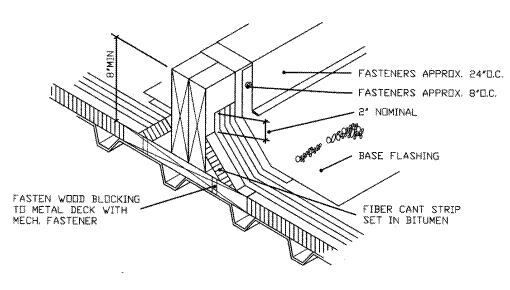
Tension splits which originate at corners of equipment, projections of wall areas, etc. may be controlled by using “Area Dividers” (see drawing next page).
- If basic repairs are made to tension splits, they should be checked during each severe cold spell during the first year to see if they are holding. Look for new splits or other evidence of stress at the same time.
AREA DIVIDER
2" = 50 mm
8" = 200 mm
24"= 610 mm
NOTE:
An area divider is designed simply as a raised double-wood member attached to a properly flashed wood base plate that is anchored to the roof deck. Area dividers should be located between the roof's expansion joints at 30 m to 60 m (100' to 200') intervals, depending upon climatic conditions and area practices. They should never restrict the flow of water.
- D. Ridging, Wrinkling, and Buckling (Bituminous Roofing)
- Description:
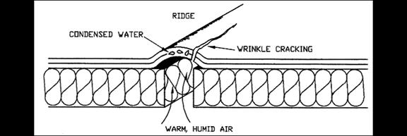
- Narrow, elongated wrinkles usually found over joints of insulation or roof deck. Expansion of felts from moisture absorption as illustrated:
- (1) Interior moisture vapour migrating to the cool underside of the membrane, condensing, then being absorbed by the organic fibres of the felt which swell into a ridge over each joint of insulation in “picture frame” pattern.
OR
- (2) An unattached or poorly attached membrane, or insulation shifting during seasonal changes, due to expansion and contraction.
OR
- (3) Curling or lifting of insulation or deck units.
OR
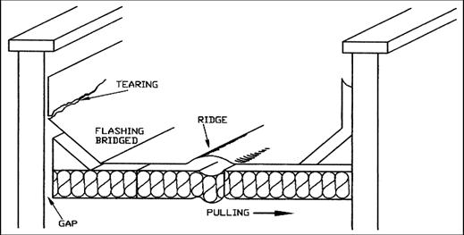
- (4) Slippage of felt plies -- ridges usually perpendicular to slope, at lower end of roof membrane. Upper edge of ridge may show loss of surfacing and exposure of plies.
- Problems:
- Crowns of wrinkles will lose surfacing and may deteriorate. Continued flexure results in fatigue or “wrinkle-cracks”. Ridges may cause ponding on low slope systems.
- Repair Procedures:
- If only a single ridge is involved, it may be preferable to cut the ridge out and apply a multi-ply basic repair.
- If there are many ridges, this would be impracticable. Clean and recoat with roof coating or mastic and aggregate, as required, to prevent further weathering.
- Note wrinkles on roof plan, and inspect crowns for cracks; repair as required.
- Check substrate for saturation, loss of bond.
- E. Ridges and Wrinkling of Single-Ply Loosely-Laid Membrane
- Description:
- Elongated wrinkles, frequently located at drains or other projections through roof membrane. May be due to inadequate attachment of substrate, curling of insulation, natural expansion and contraction of loosely-laid membrane, inadequate ballast, or “memory” of membrane after application.
- Problems:
- Exposure to weather may accelerate aging. May interfere with drainage.
- Repair Procedures:
- May be possible to pull flat or lay wrinkles under ballast for protection. If membrane is wrinkled from wind uplift, add additional ballast and carefully inspect perimeter for tears. Repair as for basic repairs.
- F. Fishmouthing or Loose Felt Laps - (Bituminous Systems)
- Description:
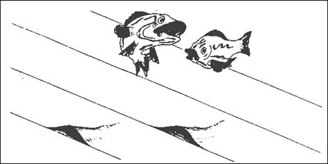
- See illustration:
- Lifting of laps, opening at edges of felts in scalloped or wavy appearance, may be caused by pulling felt during application or by using felt with damp edges.
- Problems:
- Fishmouth or loose lap may allow water penetration into the roofing system. Loss of coating leaves exposed felts.
- Repair Procedures:
- If fishmouths or loose edges extend back only a few inches, the loose material may be snipped off and discarded. An alternate procedure, especially if the fishmouths are more than 50 mm (2") deep, is to cut the membrane down the middle of the fishmouth until well-adhered material is found. Trim flaps so they lie flat. Apply mastic, press flaps into mastic, use basic repair technique over cut.
- G. Fishmouthing or Loose Felt Laps - (Single-Ply System)
- Description:
- Unbonded edge due to wrinkle at time of application, excess solvent (PVC System); contact cement not allowed to dry (elastomeric system); inadequate heat welding (PVC or modified bituminous system).
- Problems:
- Allows water penetrations, weathering.
- Repair Procedures:
- Clean area and prepare for bonding following basic repair procedures; trim excess material as required. Apply caulk to lap edge per instructions of material manufacturer. Apply surfacing to match rest of system.
- H. Punctures and Ruptures
- Description:
- Breaks in membrane from broken blisters, nails backing out of deck, dropped objects, ladders placed directly on membrane, hail, lack of membrane support, etc.
- Problems:
- Leakage
- Repair Procedures:
- Follow basic repair techniques. If membrane is unsupported, replace broken substrate (i.e. corners of insulation boards, holes in decking).
- If entire roof shows puncture damage from hail, assume that a significant amount of water has entered membranes. Applying patches or impermeable cap sheet repairs to roof is very likely to result in blisters. Use breathing insulation or vented base sheet before recovering.
- Punctures in sprayed polyurethane systems may only require application of sealant to fill indentations, followed by granules. When cured, recoat with coating to match original system. If foam is damaged to any significant extent, follow basic repair procedure for foam systems. Check for absorbed water. Cut out wet foam.
- I. Securement to Substrate - (Attached Systems)
- Description:
- Loss of bond may result in shrinkage of membrane, pulled flashings, tensile splits, wind-lifting, wrinkles or ridges.
- Problems:
- As described above.
- Repair Procedures:
- Loss of adhesion has several causes. Roof cuts should be carefully and gently done to determine extent of problem. If membrane and / or insulation is loose from a nailable deck, rows of nails or screws may be used, followed by stripping-in or recover. If loss of bond is related to water vapour attack, determine source. Reroof with proper vapour retarder and air seal may be necessary.
- On non-nailable decks such as structural concrete and precast “T” decks, it may be possible to recover and ballast without tear-off.
- Refer to Factory Mutual Loss Prevention Data 1-28 for repair procedures on insulated steel deck systems, and 1-48 for repair of wood and cementitious roofs.
- J. Fasteners Backing-Out
- Description:
- Mechanical fasteners may puncture membrane by either backing out of the deck, or by loss of thickness of nailed insulation.
- Problems:
- Punctures.
- Repair Procedures:
- Pull fasteners out where the membrane is punctured. Replace with longer fasteners or screws. Fix as for punctures.
- If roof has multiple stress points, total replacement or recover may ultimately be necessary -- determine if interior moisture is a factor, as this may be vital in design of recover.
- K. Membrane Slippage
- Description:
- Felt movement of one ply relative to another. Slippage can be of all plies, relative to substrate, or – more commonly – slippage of ply felts relative to a base sheet. Slippage can be due to wrong bitumen used, excessive interply bitumen, too much heat, too much gravity load for slope, or a combination of factors.
- Problems:
- Loss of headlap of system, resulting in less coverage than desired, formation of wrinkles or ridges, dislocation of roof jacks, tearing of membrane, etc.
- Repair Procedures:
- See surface slippage (section F).
10' = 3 m
20' = 6 m
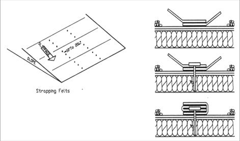
- A strapping technique can be used to stabilize a slipping membrane. If felts run perpendicular to slope, run rows of fasteners parallel to slope, nailed through strips of new roofing felt. If the felts have slipped less than 150 mm (6"), the rows of nails may be 7 m (20') apart, closing to 5 m (15') for 150 mm to 300 mm (6" to 12") slippage and 3 m (10') for more than 300 mm (12") slippage.
- Severe slippage may result in loss of coverage. Remove wrinkled felts and all surfacing, add two ply felts laid parallel to slope, backnailing to prevent slippage. Fasteners should be driven into decking, rather than into insulation, when possible.
4.6.2 Flashing Condition
- A. Base Flashings (Bituminous):
- (1) Punctures and Holes
- Description:
- Damage usually caused by foot traffic or mechanical abuse.
- Description:
- Problems:
- Leakage behind flashing into wall and roof system.
- Problems:
- Repair Procedures:
- Examine to see if flashing is supported and in contact with cant strip and wall. If under great tension, roof membrane may be shrinking and pulling flashing. Patching materials incorporate heavier-bodied flashing cements and woven jute, glass, combination flashing fabrics, or modified bituminous sheets, as aggregate protection is not possible. Mineral surface cap sheets are sometimes used as flashings in mild weather service such as on the West Coast.
- Repair Procedures:
- (2) Deterioration of Base Flashing
- Description:
- Loss of granules in cap sheets, erosion of coating and sloughing of fibres.
- Description:
- Problems:
- Loss of coating eventually leads to holes and tears in the flashing.
- Problems:
- Repair Procedures:
- Remove all loose and damaged material. Patch with reinforcements as necessary. Coat with thin applications of roof coatings. Aluminum roof coating is frequently preferred as it reduces the heat load on the wall.
- Repair Procedures:
- Some modified bituminous roof flashing materials are also recommended for general patching or recoating. They may have factory-applied foil or roofing granules for weather protection.
- Inspect flashings after rainstorm to be certain water does not stand against flashings. Also inspect for defective copings and or counter-flashing that allow water to flow against top of flashings.
- (3) Blistering of Base Flashing:
- Description:
- Similar to membrane blisters.
- Description:
- Problems:
- More vulnerable to puncture.
- Problems:
- Repair Procedures:
- If necessary, Use “X-cut” technique. Examine blister while open for cause.
- Examine top of flashing and laps to see if blister has caused looseness. Repair as necessary.
- Repair Procedures:
- (4) Open Laps in Base Flashing:
- Description:
- Laps pulled free, admitting water.
- Description:
- Problems:
- Leakage.
- Problems:
- Repair Procedures:
- Many details for flashings require mechanical attachment at the vertical lap of the flashing (but not on the 45° cant).
- Repair Procedures:
- If this has not been done, nail as specified. Use heavy flashing mastic to re-embed loose laps and strip-in with woven reinforcement. Carry repair down to membrane level by removing surfacing, patching, and re-embedding aggregate to surface.
- (5) Attachment, Buckled Flashing, Falling Away From Wall:
- Description:
- The weight of flashing materials, especially if improperly secured at the top edge, will allow them to sag away from the wall.
- Sometimes caused by relative movement of wall and membrane or shrinkage of the membrane.
- Description:
- Problems:
- Results in tears, stress concentration, water penetration at upper edge or open laps, general deterioration.
- Problems:
- Repair Procedures:
- If there is metal counter-flashing, lift it to a horizontal position being careful to avoid damage.
- Repair Procedures:
- Remove aggregate on membrane at least one foot beyond damaged area.
- Cut damaged or unsatisfactory membranes at top of cant and remove from wall.
- Nail remaining membranes to cant.
- Apply 2-ply flashing system using flashing cement. Nail 150 mm to 200 mm (6" to 8") o/c along top edge. Seal all laps and strip-in with woven fabric to match original specification (or, use modified bituminous cover strip).
- Embed aggregate over new horizontal flashing in mastic or hot bitumen.
OR
- Re-embed buckled flashing (if it is generally in good condition) into mastic, then nail along top edge.
- (6) Ridging or Wrinkling of Base Flashing
- Description:
- Elongated wrinkles, frequently on a diagonal, pointing to the ends of the wall. May indicate differential movement between wall system and roof system. Usually indicates inadequate attachment of flashing system to wall, shrinkage of roof membrane or lack of attachment to substrate.
- Description:
- Problems:
- Wrinkles ultimately result in fatigue cracks or tears in system.
- Problems:
- Repair Procedures:
- Patching using basic repair will generally hold flashing until next inspection.
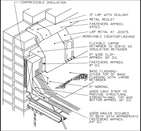
- Durable repairs require steps be taken to: Restrain relative deck-to-wall movement. (Requires structural anchoring).
- Repair Procedures:
- OR
- Construct deck mounted curb so deck and base flashing move together.
2" = 50 mm
3" = 75 mm
8" = 200 mm
16" = 400 mm
24" = 610 mm
30" = 760 mm
- NOTES:
- This detail allows wall and deck to move independently.
- This detail should be used where there is any possibility that differential movement will occur between the deck and a vertical surface, such as at a penthouse wall. The vertical wood member should be fastened to the deck only. This is one satisfactory method of joining the two-piece flashing system. Other methods may be acceptable.
- B. Counter-Flashings:
- Description:
- Counter-flashings usually consist of some form of metal attached to a wall and installed in a manner so as to cover the top of the base flashing. This diverts the flow of water away from the top edge of the base flashing.
- Movement of the metal, the parapet, or the building wall – and disintegration of the supporting mortar – are contributing factors in causing the metal to fall from the joint.
- Problems:
- When the seal over the base flashing is broken, water can enter the interior, the roof insulation, and the cant strip.
- Repair Procedures:
- Clean the mortar joint or enlarge if necessary. Return metal to original setting and secure with lead wedges -- caulk top of metal and reglet opening with construction grade caulking compound. Do not use lead wool.
- Wall-mounted counter-flashings should be reset with fasteners and recaulked as needed.
- C. Copings:
- Description:
- Copings are a cover for the wall system. They need to be well-secured to resist wind forces. Movement of both the building wall and coping cap will frequently create openings in the joints of the coping. Punctures or loss of mechanical fasteners allow water into the wall.
- Problems:
- Wall leakage and penetration under the roof membrane.
- Repair Procedures:
- If mortar is used between sections, it should be chipped from the joint at least 12 mm (1/2") deep.
- Clean joint of dirt and all contaminants.
- Apply gun-grade construction caulking into joint.
- If joints are metal seams, use appropriate solder or cover with flexible cover; some elastomeric or modified bituminous systems provide durable repairs.
- Bituminous patches, using primer, mastic and fabric will be adequate if inspected regularly.
- D. Walls
- Contact RIEI for reprints. RIEI has published a number of articles giving a fresh approach to solving wall leakage problems.
4.6.3 Roof Edging / Fascia
- Description:
- Extruded metal and formed metal gravel stops serve to terminate roof edges and to deflect overflowing water away from the wall. When in contact with bituminous membranes, the metal may split the membrane, starting at the joint of the metal.
- Problems:
- Leakage into the roof system-splits leading into BUR system.
- Repair Procedures:
- Basic techniques for splits will generally hold for a year or so.
- Long term repairs suggest raising the edge by using new wood blocking, laying new ply felts over the curb but under the metal, and replacing the metal.
- When drainage is necessary, details may be modified as in a scupper through roof edge detail.
- PVC-coated metal systems are not butted together, but leave a 6 mm to 12 mm (1/4" to 1/2") gap which is covered with PVC film. (Similar details are used for Hypalon and CPE clad metal).
- Membrane sheets which have appreciable flexibility at low temperatures may provide more durable patches.
4.6.4 Roof Penetrations
Equipment Base Flashing – See wall base flashings.
Equipment Housing – problems sometimes related to poor equipment design, open or missing hatches, open seams. Metal curbs should be insulated, and wood nailers are necessary to secure base flashing. All equipment should be mounted on wood curbs.
Equipment Operation – chemical or physical attack can quickly degrade a roofing system. Spills of oils should be avoided by using retention pans filled with sand. The sand should be replaced as necessary. Condensate should be directed to drains, or new drains should be added as necessary.
Physical abuse can be minimized by the use of traffic pads: asphalt planks on bituminous roofing; concrete pads, sometimes with a polystyrene cushion; or polyester fleece on elastomeric / thermoplastic sheets. Polystyrene must be isolated from PVC membranes. Rubber pads can be used on elastomeric membranes.
Roof jacks and vents are usually attached to the roof membrane by laying the horizontal flange on the membrane, bedded in roofing cement. The flanges are stripped in with roofing felt. Examine for splitting at corners, loss of bond at stripping.
4.6.5 Expansion Joint Covers
Expansion joint covers are designed to allow for movement between sections of a structure.
All-metal covers are subject to fatigue failure. Use elastomeric patch for best results.
Metal-Elastomer combinations may also be repaired with elastomeric patching materials. Basic components usually include primer, uncured elastomeric sheet, adhesive, caulk.
DO NOT COAT elastomeric joint covers with bituminous substances. The coatings will concentrate stresses and cause premature failure.
Locate all expansion joint covers up and out of the water line.
4.6.6 Pitch-Pans
These pans are designed to surround penetrations in the roof deck. They are generally plugged with compressible, conformable filler material, then filled with bitumen or roof cement which is intended to form a tight bond to the walls of the pan as well as the structural support, pipe, etc.
- The pans must be kept full of bitumen or roof cement at all times. The bitumen should be sloped towards the outside edges.
- Elastomeric fillers may provide more durable results than bitumen.
- Metal umbrella details, welded to the support, provide a means to counterflash the penetrations.
- Curbed details have been found to be much more durable than pitch pockets. Existing pitch pockets must be inspected regularly and filled as required.
5 Summary
Roof inspections and basic repairs can add years of service to a roof system. Good housekeeping, keeping a roof free of debris and vegetation are also important. Damage, if detected early, can almost always be repaired for just a few dollars.
- This manual has been written with that goal in mind. For complicated repairs, complete surveys, etc. there are many fine sources of help, either through materials producers, roof survey firms or roofing contractors. The key elements in any event are to be aware of the roof system and to provide regular, systematic care.
6 R.I.E.I. Semi-annual Maintenance Inspection Checklist
7 Historical Record
.1 Building & Location
| Firm | Contact | Telephone | |
| Architect | |||
| General Contractor | |||
| Roofing Contractor | |||
| Roof Consultant | |||
| Test Laboratory | |||
| Roofing Materials Manufacturer | |||
| Deck Contractor | |||
| Decking Materials Manufacturer | |||
| Others |
.2 Materials and Specifications (As-Built)
- Roof Deck (Type, thickness or gauge, coating or treatments, method of attachment, side lap fastening, lap requirements, span, etc.)
- Roof Drainage (Designed slope, slope of valleys, use of crickets, scuppers, drains set in sumps, etc.)
- Vapour Retarders (When used, identify trade names, millimetre thickness, how sealed at ends and side laps, penetrations, describe quantity of adhesive and method of application. Describe edge seals if used.)
- Thermal Insulation (List all trade names, thickness and type of each layer, define published RSI Values ('R' Values), method of attachment to substrate and layer to layer. Identify code numbers, CGSB, CSA, U.L.C., U.L., or F.M. labels, method of breaking joints, etc.)
- Roof Membrane (List all trade names, retain samples 215 mm x 275 mm (8-1/2" x 11") of each type sheet material. If bituminous, list all bitumens used by CSA (ASTM) designation and quantities specified for inter-ply and surfacing. If elastoplastic, describe all adhesives or solvents used, method of attachment i.e. loose-laid, partial, etc. Describe lapping, exposure, other details of importance.)
- Flashings (Describe base flashing materials such as cant strips, types of films or felts used, priming of walls, trade names and description or thickness, specified fasteners and frequency, surfacing, list flashing spec numbers and manufacturer's details.)
- Sheet Metal (Describe types used, detail no.'s, fascia details, lapping, stripping, securement, etc. as applicable.)
.3 Date of Completion of Initial Roof Application __________________________
- Roof Guarantee by ________________ Expiration Date ________________________
.4 Buildings Usage (Include interior temperature, relative humidity, chemical processing, vibration, etc.)
.5 Previous Maintenance, Surfacing or Repairs (Briefly summarize and attach previous reports.)
8 RoofStar Guarantee Program Roofing Maintenance Checklist
| BUILDING | DATE | |||||
| LOCATION | INSPECTOR | |||||
| Problem | ||||||
| O.K. | Major | Minor | Observation | Date of Repair | ||
| I. ROOF CONDITION | ||||||
| A. | General Appearance | |||||
| Debris | ||||||
| Drainage | ||||||
| Physical Damage | ||||||
| General Condition | ||||||
| New Equipment / Alterations | ||||||
| Other | ||||||
| B. | Surface Condition | |||||
| Bare Spots in Gravel | ||||||
| Alligatoring / Cracking | ||||||
| Slippage | ||||||
| Other | ||||||
| C. | Membrane Condition | |||||
| Blistering / Splitting / Ridging | ||||||
| Physical Damage | ||||||
| Other | ||||||
| II. FLASHING CONDITION | ||||||
| A. | Membrane Flashing | |||||
| Physical Damage | ||||||
| Deterioration / Blistering / Open Laps | ||||||
| Attachment | ||||||
| Other | ||||||
| B. | Metal Flashings | |||||
| Physical Damage | ||||||
| Attachment / Fasteners | ||||||
| Corrosion | ||||||
| Drainage | ||||||
| Other | ||||||
| Problem | ||||||
| O.K. | Major | Minor | Observation | Date of Repair | ||
| I. ROOF PENETRATIONS | ||||||
| A. | Equipment | |||||
| 1. | ||||||
| 2. | ||||||
| Open Laps | ||||||
| Punctures | ||||||
| Attachment | ||||||
| Other | ||||||
| B. | Equipment Housing | |||||
| C. | Equipment Operation | |||||
| D. | Roof Jacks / Vents | |||||
| E. | Roof Drains | |||||
| Type | ||||||
| Condition | ||||||
| Quantity | ||||||
| Overflows | ||||||
| IV. EXPANSION JOINT COVERS | ||||||
| V. GUM PANS | ||||||
| Fill Material Shrinkage | ||||||
| Other | ||||||
| VI. OTHER OBSERVATIONS | ||||||
| 1. | ||||||
| 2. | ||||||
| 3. | ||||||
© RCABC 2026
RoofStarTM is a registered Trademark of the RCABC.
No reproduction of this material, in whole or in part, is lawful without the expressed permission of the RCABC Guarantee Corp.


