Template:Part 6 - TPO
Template:Part 6 - TPO
1 General
1.1 Intent
Air and vapour control layers, along with thermal barriers, water resistive barriers and water-shedding surfaces, serve to separate the outside environment from the interior environments of a structure. Continuous air control layers are perhaps the most critical. Codes in each jurisdiction, and the National Energy Code (2011), require the selection and proper installation of “a continuous air barrier system comprised of air-barrier assemblies to control air leakage into and out of the conditioned space” (NEC 2011).
Continuity of the air and vapour control layers from the wall systems and roof systems is essential to the satisfactory performance of either or both. Therefore, proper connection between air and vapour control systems is essential, and the responsibility of both the Design Authority and trades constructing walls and roofs.
Air control layers control “flow of air through the building enclosure, either inward or outward” (Guide for Designing Energy Efficient Building Enclosures, Homeowner Protection Office). Controlling air flow into and out of conditioned spaces affects the performance of “thermally efficient enclosure assemblies” (ibid), impacts the potential for condensation in between materials, and directly influences rain water penetration of the building envelope. Some air control layers are considered vapour permeable, others vapour-impermeable. The suitability of one over the other, in the application of a roof system, is left to the discernment of the Design Authority. Consequently, the RoofStar Guarantee Program strongly recommends that designers and builders of roof systems intended to qualify for a RoofStar Guarantee carefully consider the regulatory design and installation requirements for effective, continuous air control systems.
Vapour control layers regulate or prohibit the movement of water vapour from one space to another by means of diffusion. Consequently, these control layers are referred to as either vapour-permeable or impermeable. Diffusion is a slow process, in contrast to air movement, and its regulation is not always mandatory or even desirable. Therefore, because continuous vapour control layers “are not needed within all climate zones and assemblies”, they are considered non-critical and may be left to the discretion of the Design Authority. Nevertheless, where continuous vapour control layers are required and specified by Code, the RoofStar Guarantee Program requires that a suitable vapour control system be selected by the Design Authority and properly installed by the Contractor in conformity with the vapour control layer manufacturer’s published instructions, and with the Design Authority’s specified details.
Any references in this Manual to installation methodologies, and any construction details that show air and vapour control layers, are merely illustrative and not prescriptive. Installers of continuous air and vapour control layer systems are urged to understand and comply with best practices for their application.
1.2 Limitations and Exclusions
- Air and vapour control layer performance is not part of the RoofStar Guarantee, and air and vapour control materials are not listed in the Accepted Materials Division of this Manual. Therefore, the decision to specify air and vapour control layers, the placement of continuous air and vapour control layers in relation to a roof system and its components, and the selection of suitable materials for that application, is the sole responsibility of the Design Authority. The Design Authority is urged to review and consider the performance characteristics of materials available for such applications.
- Neither the RoofStar Guarantee Program nor the Contractor will accept any responsibility for damage to, or failure of, the roof system caused by the use or absence of air or vapour control layers.
- In some roof assembly designs, the required underlayment may serve as an air control layer, vapour control layer, or both; this is dependent upon the properties of the material to be used, and will be subject to the designer’s modelling of the assembly. Consult the Technical Data Sheets for suitable materials.
1.3 Air and Vapour Controls for High-Humidity Building Interiors
- Careful consideration should be given to the performance characteristics of air and vapour control layers when specifying such a membrane for roof systems constructed over high-humidity building interiors. These types of building interiors include (but are not limited to)
- swimming pools
- commercial laundry facilities
- large aquariums
- paper mills
Roof systems for facilities such as these, with high-humidity environments, may be susceptible to the accumulation of moisture within the roof system unless effective air and vapour controls are installed.
2 Materials
- The material selected for air and vapour control layers must be compatible with any other materials in the roof or wall assembly to which the control layer may come in contact. This includes, without limitation, contact with primers and adhesives, substrates, solvents and cleaners.
- Self-adhering or adhesive-applied materials should be considered as alternatives to torch-applied membranes when the substrate to which they will be applied is combustible, or when nearby structures, openings or materials present a fire hazard. In the alternative, a suitable separation or overlay material as protection from open flame is acceptable. The application of materials to a combustible surface, using a torch, is strictly prohibited.
- Fully supported air and vapour control layers should possess a minimum published static puncture resistance rating of 150 N (34 lbf) (ref. CGSB-37.56-M for both test method and standard limits) and be either self-adhering or torch-applied; a high puncture resistance is necessary for the membrane to withstand accidental damage during construction. For unsupported air and vapour control layers, see 6.2 (4) below. Therefore, while responsibility for the selection of suitable air and vapour control layers rests with the Design Authority, a roof designed and built to qualify for a RoofStar Guarantee shall not include the following:
- polyethylene sheet plastic.
- bitumen-impregnated kraft paper.
- Notwithstanding any of the foregoing, the RoofStar Guarantee Program strongly recommends that any air or vapour control systems be installed over a smooth, continuous plane (for example, concrete or plywood). Consequently, a deck overlay board installed on corrugated steel roof decks in highly recommended. Where no deck overlay board is installed and the air and vapour control layers are partially unsupported (for example, on a steel deck), the control layers each must have a published static puncture resistance of at least 400 N (90 lbf). Furthermore, both the side laps and end laps must be fully supported.
- Should the air or vapour control layers be used as a temporary roof during project construction by either the Contractor or by other trades, a minimum 2mm thick bituminous membrane is recommended.
- Because curing concrete releases considerable moisture that can compromise the performance of a roof system, a vapour control layer installed on new concrete decks (28 days or older) must be selected to prevent condensation inside the roof system. A membrane with a permeability of 0.01 perms (Class I) is recommended. Nevertheless, the selection of the vapour control material is the responsibility of the Design Authority.
3 Application
- Proper installation and continuity of air and vapour control layers within the roof assembly is the responsibility of the Contractor. Therefore, air and vapour control layers in the roof assembly must
- extend beyond the end of the roof assembly at least 100 mm (4”), in new construction, to provide sufficient room for the installation of matching control layers to so that they provide a positive (water-shedding) lap seal union between courses of material.
- be sealed to matching control layers in the wall assembly, for roof replacement projects.
- Installation must be smooth and uniform, without wrinkles or fish-mouths, and must also conform to the manufacturer’s published requirements and the Design Authority’s design details.
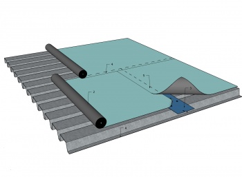
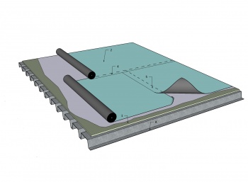
- All membrane side and end laps must be fully supported, in the field and at transitions with curbs, parapets, walls and penetrations. When self-adhered membranes are applied directly to a steel supporting deck,
- membranes should be oriented parallel to the direction of deck flutes.
- membrane laps and changes in plane must be supported by deck flutes or flat metal supports secured to the deck to span gaps. Metal supports must be
- fabricated from pre-finished steel with a thickness no less than 24 Gauge.
- secured to the deck with no fewer than two (2) compatible screw fasteners per flute.
- The application of materials to an unprotected combustible material, using a torch, is strictly prohibited.
- All combustible materials MUST be protected from open flame by an acceptable separation or overlay material. This includes, without limitation, combustible materials
- on decks, walls, blocking, and canted edges.
- hidden or obscured within voids, cracks or orifices.
- When a torch-applied base membrane is specified over combustible materials, all joints between overlay panels, and at roof-wall transitions, must be sealed with the primary membrane manufacturer’s approved self-adhered membrane or tapes. Alternatively, refer to 10.3.3 Alternative Approaches to Membrane Flashing in the RoofStar Guarantee Standards for SBS Modified Bitumen Membrane System.
See Figures 6.3.1-1 and 6.3.1-2.


