
(Draft) Notes to GLW Standard
(Draft) Notes to GLW Standard
Division B - Standards
Notes to RGC Standard for Grade-level Waterproofing Systems
(Notes are explanatory and non-binding, each provided to support the requirements, guiding principles and recommendations of the Standard.)
Notes to Part 1
A-1.1.2.4. Quality Assurance
- An independent Observer plays a key role in every project for which a building owner has paid a fee to qualify it for a RoofStar Guarantee. Each Observer is independently trained as a professional and therefore understands the responsibilities that typically encompass the role. However, there are additional responsibilities that come with the designation "Accepted Observer", which is particular to the RoofStar Guarantee Program. To ensure that Observers fully understand the purpose, scope, and direction of the Program, the RGC provides training for Observers, specifically geared to the RGC's Program. The status of "Accepted" does not mean the Observer is contracted, or endorsed, by the RGC; it means that the Observer has achieved a satisfactory level of competency with the RoofStar Guarantee Program, required by the RGC to be qualified to provide Quality Assurance observations (limited inspections) on behalf of an Owner.
- Where an Observer or Observer Firm also engages in the work of consulting (providing advice and design work), the work of the consultant is considered by the RGC to be wholly separate from the role of Observer.
A-1.1.3.1. Permitted Waterproofing Systems
- Designing a good waterproofing assembly begins with the end in mind and an answer to the essential question, “What purpose will the system serve?” For example, the waterproofing assembly may
- simply weatherproof the building interior,
- provide a location for building equipment and services, or
- support liveable (amenity) spaces.
- The finished system surface is defined by whatever is placed on the membrane, which may be insulation, ballast, pavers or overburden. These materials will displace water and therefore affect the height of membrane flashing needed to prevent water ingress. The definition of finished system surface is illustrated below in Figure 1.3.2-2. See also Article 1.1.1.4., "Definitions".
Figure 1.1.3.1.-A (Protected Membrane System)(Click to expand) 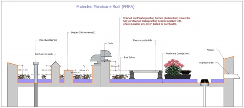
A-1.1.3.3. Membrane Integrity Scans
- An integrity scan is performed after the installation of the waterproofing system, before any overburden, equipment or amenity space is installed on top of it. An integrity scan typically uses low-voltage electrical current to detect even the smallest breaches in the roof membrane, but some waterproofing materials may require the use of other technologies to verify the system’s integrity. Therefore, Design Authority should specify the appropriate technology, keeping in mind the limitations of each scan and detection methodology, and of the membranes that are specified.
- Neither an integrity scan nor an Electronic Leak Detection (ELD) system are considered Accepted Materials, but firms that provide these services are nevertheless specifically recognized and approved by the RoofStar Guarantee Program.
A-1.1.3.4. Electronic Leak Detection
- Electronic Leak Detection (ELD) utilizes low-voltage electrical current, typically conducted through wires installed in a grid pattern. ELD technologies are used in response to a leak, to isolate its location in order to minimize investigation time and material removal. This can benefit a building owner who will have to bear the costs of demolition or overburden removal when the standard limits of coverage afforded by the RoofStar Guarantee are exceeded by the project design and construction. ELD technologies may be passive (installed but not monitored) or actively monitored (by the installer, through real-time data collection).
A-1.1.3.5. Hot Works
- When any portion of a waterproofing system is installed with heat, the work is classified as Hot Works. Some tools used in the course of Hot Works can ignite combustible materials, and some building environments are more sensitive to fire than others, such as a building containing or in close proximity to flammable liquids. Hot works may occur during
- tear off (sparks).
- deck preparation (drying wet surfaces).
- cold temperatures (warming materials or surfaces).
- equipment use (sparks within electrical tools, or from cutting, drilling, or grinding metal, concrete, stone, or other hard surface products).
- membrane installation (with the means of a kettle, hot-air welder, or open flame torch).
A-1.1.4. Alterations and Additions
- As a waterproofing system ages, is neglected or is damaged, it may lose its ability to perform reliably and effectively, necessitating replacement. System replacement, whether made in whole or in part, should be undertaken with the Quality Assurance and Quality Control provided for under the RoofStar Guarantee Program. Regardless of the approach to replacement waterproofing, the existing deck structure must be capable of supporting all dead and live loads. Furthermore, the deck must be capable of supporting any additional dead loads of the new waterproofing system.
- Three types of waterproofing system replacement are contemplated and permitted (with varying degrees of limitations and conditions) under the RoofStar Guarantee Program:
- Complete system replacement - removal and replacement of all waterproofing system components, except for the supporting deck structure.
- Partial system replacement – typically, removal and replacement of the waterproofing membrane, while retaining existing waterproofing system components (i.e., insulation, ballast).
- Recovering - installation of a new membrane over an existing membrane, while retaining some or all of the other waterproofing system materials (NOTE: Recovering is permitted only with a written Variance issued by the Guarantor).
- Qualifying and construction conditions and limitations for each of these replacement options are outlined in Subsection 1.1.4. Other conditions and limitation may be determined by the Guarantor subject to the nature and specifications of the replacement project.
A-1.1.4.4. Membrane Recovering
- When membrane replacement is not practical, membrane recovering is an acceptable method for renewing the weatherside surface of a waterproofing assembly when most if not all of the other components remain undamaged or undisturbed. Membrane recovering requires an assessment beforehand by a qualified professional, to determine the integrity of the existing system. The assessment report is then provided to the Guarantor as part of the submission for a Variance. However, because the requirements in Part 3 apply to both new and replacement waterproofing, securing new materials on top of existing materials becomes challenging and critical, particularly when the waterproofing system is subject to wind loads.
- Every waterproofing assembly constitutes a chain of connected parts and that 'chain of connectivity' is predicated on both adequate ballast (for protected, insulated systems) and the integrity of the adhesion bond between the waterproofing membrane and the deck. Because adhesion bonds may not provide the hold-down strength they once did when they were new, the RGC requires the Design Authority to conduct adhesion tests to confirm that the existing assembly exceeds the Code requirement for design loads. When an in-service membrane is demonstrably secure (fully bonded to the roof deck – adhesion of the membrane for wind uplift resistance must be tested, and the test results submitted to the Guarantor with the request for a Variance), it is blister-free, and it is free of damage, the Guarantor may permit the application of a new membrane directly to the existing membrane, without requiring membrane removal or the application of an intermediate overlay board.
A-1.3.2.2. Workmanship
- While integrity and functionality of grade-level waterproofing is the foundation of a RoofStar Guarantee, it is no less important to ensure that the finished project exhibits excellent workmanship.
Notes to Part 2
A-2 Scope and Application of Part 2
- Part 2 addresses deck and wall materials, deck slope, and deck and wall conditions. It does not address construction or installation of decks and walls, which is the work of other trades. For the preparation of a roof deck to render a deck or wall suitable for roofing, refer to Part 9 and Part 10, in the articles pertaining the substrate preparation.
A-2.1.5.1. Steel Roof Decks
- Steel decks are constructed of light gauge (usually 22, 20, or 18 gauge) cold-rolled steel sections (panels) that are usually galvanized. In cross-section the panels are ribbed, with the ribs usually spaced at 150 mm (6") O.C. The ribs provide the strength and rigidity of the panels. Steel decks are generally supported by open-web steel joist framing and are welded or mechanically fastened to the framework.
A-2.1.5.2. Concrete Roof Decks
- Concrete decks to which a waterproofing system may be applied include
- Cast-in-place.
- Pre-cast panels.
- Pre-stressed panels.
- Lightweight.
A-2.1.7. Walls
- Walls and the field of a waterproofing assembly intersect either directly (where the wall structurally connects to the deck structure, so that both move together), or indirectly (where the deck structure and the wall structure are independent of each other, so that the movement of one does not affect the other). These locations require an expansion joint.
Notes to Part 3
A-3.1.1.1. Scope
- Wind exerts tremendous forces on exposed horizontal surfaces. While wind is commonly experienced as a “pushing” force, wind also generates “negative” (pulling or “uplift”) forces, particularly on waterproofing systems. These powerful forces can, if the waterproofing systems is poorly secured to the building’s structural elements, detach in whole or in part from the building.
- The Code refers to these calculated forces as specified wind loads, which act in concert with the “responses of the [wind-exposed] system…[and therefore] are time-and-space dependent, and thus are dynamic in nature.” (CSA Standard A123.21, "Standard test method for the dynamic wind uplift resistance of membrane-roofing systems" (latest edition), 4.1). Because of this dynamic interplay between loads and a building’s structural capacities (the load paths between the waterproofing system and other structural elements of the building), the Design Authority must design a waterproofing system to effectively absorb and mitigate specified wind loads.
- As stated earlier, the calculation of Specified Wind Loads falls under "British Columbia Building Code", Division B, Subsection 4.1.7., "Wind Loads", while the securement of the waterproofing system to resist Specified Wind Loads is governed by the "British Columbia Building Code", Division B, Article 5.2.2.2., "Determination of Wind Load".
Notes to Part 4
Notes to Part 5
A-5 Deck and Wall Overlays
- This Part addresses materials that are acceptable as overlays used to render a deck or wall surface suitable for roofing. This Part supports the substrate preparation requirements in Parts 9 and 10.
Notes to Part 6
A-6 Air and Vapour Controls
- Part 6 is a boilerplate wording included in every Standard of the RoofStar Guarantee Program, regardless of whether or how air and vapour controls are used in a roof assembly.
- Air and vapour controls, whether manufactured as sheet products or as liquids, form a critical component of the suite of building enclosure systems used to regulate the movement of air and water vapour in and out of the building. Because continuity is critical not only within an assembly but also between assemblies, performance of air and vapour control materials is not covered by the RoofStar Guarantee; the RoofStar Guarantee Program is limited to the scope of a roof system, and therefore it has no control over the construction or performance of adjoining assemblies, such as walls, which may adversely impact the performance of the roof system. Nevertheless, the choice of materials used in a roof system is still critical for its performance. Therefore, this Part prohibits certain materials because, from a constructability standpoint, they are difficult to seal (to achieve continuity) and are often fragile and prone to puncture during construction. Furthermore, this Part includes both design and construction requirements intended to achieve continuity, since the transfer of air and the movement of water vapour into the roof system can produce false leaks that undermine the objectives of the Standard.
A-6.1.1.1. Scope
- Air and vapour control layers, along with thermal barriers, water resistive barriers and water-shedding surfaces, serve to separate the outside environment from the interior environments of a structure. Continuous air control layers are perhaps the most critical. Codes in each jurisdiction, and the "2020 National Energy Code of Canada for Buildings" (NECB), require the selection and proper installation of “a continuous air barrier system comprised of air-barrier assemblies"..."to control air leakage into and out of the conditioned space” ("National Energy Code of Canada for Buildings", Part 3, Article 3.2.4.1., "General").
- Air control layers regulate and often prohibit the “flow of air through the building enclosure, either inward or outward” (Guide for Designing Energy Efficient Building Enclosures, Homeowner Protection Office). Controlling air flow into and out of conditioned spaces affects the performance of “thermally efficient enclosure assemblies” (ibid), impacts the potential for condensation in between materials, and directly influences rain water penetration of the building envelope.
- Vapour control layers regulate or prohibit the movement of water vapour from one space to another by means of diffusion. Consequently, these control layers are referred to as either vapour-permeable or impermeable. Diffusion is a slow process, in contrast to air movement, and its regulation is not always mandatory or even desirable.
- Any references in this Manual to installation methodologies, and any construction details that show air and vapour control layers, are merely illustrative and not prescriptive. Installers of continuous air and vapour control layer systems are urged to understand and comply with best practices for their application.
A-6.1.3.1. Responsibility for Design
- Air and vapour control layer performance is not part of the RoofStar Guarantee, and air and vapour control materials are not listed in Division C.
- In some waterproofing assembly designs, materials that control air movement may also serve as a vapour control layer; this is dependent upon the properties of the material to be used and will be subject to the designer’s modelling of the assembly. Consult the Technical Data Sheets for suitable materials.
A-6.2.1.2. Prohibited Materials for RoofStar Guarantee
- Constructability, and resistance to damage, heat, and to solvent-based products, are key properties of air and vapour control materials. While the RoofStar Guarantee does not extend coverage to air and vapour control materials, or to their performance (Ref. Note A-6, "Air and Vapour Controls"), leaks through or past damaged or poorly sealed materials can adversely affect the performance of the waterproofing system, particularly where it joins wall assemblies. For this reason, both polyethylene plastic sheet products and bitumen-impregnated kraft paper are not permitted in any part of a waterproofing system that qualifies for a RoofStar Guarantee; both materials are easily damaged (punctured) during construction, and proper sealing of each material to itself and to adjoining materials is difficult.
Notes to Part 7
A-7.1.3.1 Responsibility for Design
- Insulation materials rely on various standards for the determination of thermal resistance, which means that not all data can be easily compared. Furthermore, not all insulation products perform with consistent thermal resistance as temperature changes, and some insulation performance declines with age. Therefore, refer to the "Long-term Thermal Resistance" (LTTR) for each insulation product, in relation to the product's placement within the waterproofing assembly and the anticipated outside and interior climates of the building.
- Also see the "British Columbia Building Code", Division B, Part 10 (Ref. Div. B, Section 9.25., "Heat Transfer, Air Leakage and Condensation Control" for structures governed by Part 9), together with relevant requirements in Division A and Division C of the Building Code.
A-7.1.3.4. Thermal Resistance and Layering
- In warm seasons, high temperatures may adversely affect the performance and stability of some insulation. Consequently, the requirement which limits panel size in single-layer applications ensures that inevitable gaps between adjacent panels are kept to a minimum. Combining insulation types in a roof system may help mitigate these temperature swings and the consequence of thermal contraction. The Design Authority therefore must consider these variables when specifying materials and their installation. || 2023-June-16 }}
- While multi-layering insulation is required when the cumulative thermal resistance of all insulation exceeds RSI-2.64 (R-15), it is important to note that most insulation types naturally experience dimensional change in all 3 planes as outside temperatures and sun exposure change throughout the day (mineral fibre insulation being the general exception). The degree of expansion or contraction directly corresponds with the thickness of the panel; the greater the thickness and panel size, the larger the movement. Considerable movement may create unexpected issues with the roof; shrinkage and resulting gaps between insulation panels may introduce thermal loss, and movement that telegraphs to the supporting roof surface may produce membrane wrinkling. To reduce the consequences of thermal movement, the Design Authority should consider specifying maximum layer thickness; any leaks attributed to roof system movement are excluded from coverage under a RoofStar Guarantee.
- The "Long-Term Thermal Resistance" (LTTR) measurement of closed-cell insulation materials remains the standard by which insulation performance is measured. Published R-values should reflect the LTTR of the material. In Canada, the standard that applies to insulation used in waterproofing systems, for the accurate measurement of thermal resistance, is CAN/ULC-S770 ("Standard Test Method for Determination of Long-Term Thermal Resistance of Closed-Cell Thermal Insulating Foams").
Notes to Part 8
Notes to Part 9
A-9.3.2.2.(2) Preparation of Substrate
- Proper water curing techniques are strongly recommended and include continual or frequent applications of water by ponding or immersion, spraying or fogging. Concrete decks cured with compounds or sealants may not have acceptable surfaces to receive adhered waterproofing membranes. When concrete curing compounds are used on waterproofing decks removal of the compounds by mechanical means, may be necessary prior to installation of membranes, and such removal is the responsibly of others not the waterproofing contractor.
Notes to Part 10
A-10.1.6.1. Expansion Joints
- Waterproofing assembly expansion joints, or movement joints, are designed to safely absorb thermal expansion and contraction of materials, or to absorb vibration. This is especially critical on large areas of a project where the expansion and contraction rates of materials can adversely affect membranes; by dividing the roof into smaller area units, these effects can be ameliorated.
- Expansion joints also allow for movement caused by settlement and earthquakes.
A-10.1.6.2. Control Joints (System Dividers)
- Control joints (sometimes referred to as roof dividers) are site-built but relatively uncommon for roofs with flexible membranes. They are designed to help control thermal expansion and contraction stresses in the roof system where no structural expansion joint has been provided in the building design, by dividing large roof areas into smaller ones. Control joints may be present on older roofs with built-up roof systems, and will have to be taken into consideration by the Design Authority; in some cases, control joints may be eliminated for replacement roofing. Still, control joints may be employed by the Design Authority to control expansion and contraction of any materials in the roof system, or for dividing existing roof areas for phased replacement roofing.
- Control joints may be employed to divide a large roof area into smaller roof areas, for the purpose of phasing replacement roofing.
A-10.2.1.1.(2)(3) Flashing Membrane
- Some membranes that satisfy the criteria in Article 10.2.1.1. are listed in Division C but were accepted for use on water-shedding roof systems (i.e., Architectural Sheet Metal, or Asphalt Shingles). When the Design Authority specifies one of these materials for application on a tall parapet, it must be declared suitable for the purpose by the manufacturer of that membrane.
A-10.3.7.2. Intersections with Water-Shedding Roofs
- The maximum water level is the point where water naturally spills off a system (for example, through an overflow drain). When a waterproofing system is designed with parapets and mechanical (plumbed) drains but is not constructed with overflows, the spill-over point will be the top of the lowest edge detail. typically a parapet (See Article 11.1.4.2.). Drains may be unmaintained and severe storms or freeze-thaw cycling during winter months may interfere with a waterproofing system's ability to drain. Therefore, the waterproofing (and also the load design) should allow for a worst case scenario in which the waterproofing system to its maximum capacity. Contemplating such a scenario should give the designer pause when considering low-clearance openings in walls (i.e., doors, windows, and ventilation grilles), which may serve as de facto 'overflows' when other drains are inoperable.
- The effects of weather cannot be overstated. While an absence of maintenance is often faulted for blocked drains and overflows, snow and ice can radically alter the drainage of a waterproofing assembly; in some instances, where freezing rain coats snow on the assembly, the encrusted top surface of the snow forms a new plane of drainage. Seasonal phenomena like this affect every detail on an assembly - penetrations, curbs, and perimeter membrane flashing. While RGC Standards publish minimum requirements for membrane flashing, those minimums do not contemplate every possible condition that might affect a building. It is therefore incumbent upon the Design Authority to specify membrane flashing heights for the expected service conditions of the roof, for its location (Ref. British Columbia Building Code, Div. A, Functional Statement 80).

Notes to Part 11
A-11.1.4.2. Scuppers and Overflows
- The primary function of an overflow is to keep a roof from collapsing when primary roof drains are plugged or cannot drain heavy rainfall. New and existing buildings should incorporate overflows to handle large rain events. Refer to the "British Columbia Building Code" and the "British Columbia Plumbing Code" for drain sizing and location requirements.
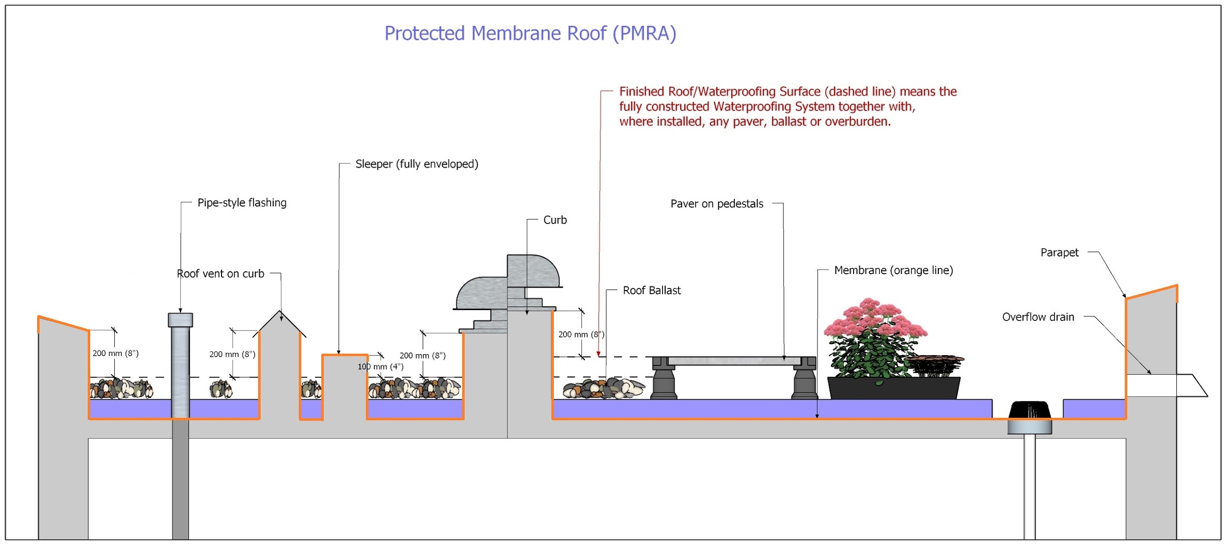
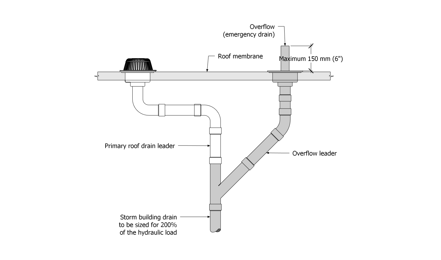
- Where overflows are not located at the roof edge and are instead located in the roof field, they should be plumbed separately from primary roof drains. Currently, the National Plumbing Code of Canada (and the British Columbia Plumbing Code which is modelled after it) do not stipulate how overflows must be plumbed. However, that is expected to change with the 2025 NPC and subsequently with the British Columbia Plumbing Code. “Emergency roof drainage systems” will have to be independent of (separately plumbed from) the “primary roof drainage system”. Furthermore, “A storm building drain serving both the primary and emergency roof drainage systems, as described in Clause 2.6.6.6.(3)(a), shall be sized for 200% of the calculated hydraulic load determined in accordance with Subsection 2.4.10.” (Proposed Change 1790, Canadian Board for Harmonized Construction Codes, February 2024). The illustration below, adapted from PC1790, captures the concept. However, overflows situated at the roof perimeter are recommended, where the design permits it; overflows that share drain leaders, regardless of leader capacity, should be avoided .
Figure A-11.1.4.2.-1 Illustration adapted from PC1790, NPC
Forming Part of Note A-11.1.4.2.
(Click to expand illustration)
- The location of the drainage plane depends on the type of roof system. On a conventionally insulated roof with an exposed membrane (no overburden), the drainage plane and the field membrane are synonymous. However, overburden displaces water upward, shifting the location of the drainage plane with it. The location of overflows must take this into account .
- The drainage plane of a protected membrane roof assembly is also affected by displacement (XPS insulation and ballast), and also by how water-permeable the filtration layer is. Low-permeable materials tend to direct most water to the drains across the filtration layer plane, so that very little water finds its way down to the roof membrane. Highly permeable filtration materials, when they are new, admit considerable water into the roof system; water works its way down to the roof membrane, between and around XPS panels. However, as protected membrane roofs age, water-permeable filtration layers will tend to cake with fine debris so that they function more like impermeable fabrics .
- When overflows are located at the same plane as overburden or stone roof ballast, they must be protected with ballast guards from blockage by water-displaced materials .
A-11.1.4.3. Membrane Gutters
- Gutters designed with downward-draining flanged drains need sufficient width to properly secure and seal the flange to the gutter membrane system. Gutters narrower than 300 mm compromise this critical detail, either by forcing the installer to trim the flange to fit the gutter width (which can compromise securement of the drain body), or by reducing the breadth of membrane needed to properly seal the drain flange to the gutter bottom. Gutters designed with cast-iron drains must be at least 100 mm (4") wider than the width of the drain body, to permit a sufficient membrane seal; more width is better, improving the effectiveness of the drain installation.
A-11.2.1.2. Roof Drains and Scuppers
- Roof drains are comprised mainly of two parts: a bowl or flange that is affixed to the roof deck with mechanical fasteners or a proprietary clamping mechanism; and an integral drain stem that connects the bowl or flange to the leader. Roof drains are sized according to the diameter of the drain stem. The appropriate size and number of roof drains for any given roof area is determined by the relevant building code in force (Ref. "British Columbia Plumbing Code", Division B, Article 2.4.10.4., "Hydraulic Loads from Roofs or Paved Surfaces").
- Roof drains can be further classified as internal or external. Internal roof drains are connected to leaders located and connected to a storm building drain or sewer inside the exterior surface of a building. Internal roof drains may be made of cast iron (secured to the roof assembly with clamps) or from copper or aluminum, fashioned from spun components that are welded together and incorporate a flange around the drain bowl.
- External roof drains direct storm water outside the exterior surface of a building. Scuppers and overflow drains are the common types of external roof drains, and may connect to leaders or simply drain freely. Any requirements for leaders and connections to leaders may be found in the applicable municipal and provincial building and plumbing codes (Ref. "British Columbia Building Code", Division B, Article 5.6.2.2., "Accumulation and Disposal").
Notes to Part 12
A-12.3.2.1.(14)(4) Wood Blocking to Support Metal-Flanged Flashing
- Wood blocking (Sentence 9) provides support for the edge of metal-flanged penetrations and is required by single-ply membrane manufacturers. Support for flanges must extend beyond the edge of the flange to keep the edge from cutting the membrane; hence, the 12.7 mm (1/2") requirement. In a conventionally insulated roof system, the blocking must be located directly beneath the flange. Blocking must be securely fastened to the roof structure (deck) to ensure wind uplift resistance; placement of the blocking above layers of insulation minimizes thermal loss through bridging.
- To ensure a sufficient seal between the membrane target patch and the flashing flange, the full 101.6 mm width of the flange must be retained; trimming it will reduce the contact surface area and therefore reduce the reliability of the bond.
A-12.3.2.1.(13)(4) Target Patch Seal
For the target patch membrane to achieve a good seal around the base of the penetration flashing, it must make full contact with the untrimmed surface of the flange; anything less negates the reason for the required flange width, which was instituted to ensure an adequate seal around the circumference of the flashing (See Article 12.2.1.2. for flashing properties).
Notes to Part 13
A-13.2.1.2.(3)(2) Stainless Steel
- Stainless steel is a good product to use when roof penetrations or metal flashings are exposed to constant water, are used in marine environments (salt-water), or are exposed to highly corrosive by-products from industrial sites. Stainless steel is available in two grades for the roofing industry: Grade 304 And Grade 316.
- Grade 304 and 316 stainless steels behave differently because of their molecular structure (explained below). Grade 304 can be thinner than Grade 316, because of differences in ductility. Grade 304 stainless steel is typically less costly than grade 316 stainless, but it is also suitable for applications where formability is desirable. This is why Grade 304 is permitted for linear metal flashings. Conversely, Grade 316 stainless steel is the preferred choice for environments that are highly corrosive, where the material will be consistently exposed to or immersed in water, and in applications where superior strength and hardness are required. Grade 316L has superior corrosion resistance over Grade 316 stainless steel because of its low (L) carbon content. Therefore, for consistency in RGC requirements, and to improve the corrosion resistance of stainless steel used in the RoofStar Guarantee Program, the Standard recognizes only Grade 316L for roof drains, overflows, and penetration flashings.
- Grade 304 stainless steel is perhaps the most common austenitic stainless steel. This type of stainless steel is characterized by a specific crystal structure called austenite. The result is a stainless steel that resists corrosion, is highly ductile, and exhibits good welding properties. In addition to iron, grade 304 stainless steel contains a high nickel content (8 to 10.5 percent by weight on average), and a high amount of chromium (18 to 20 percent by weight). It also contains other alloying elements such as manganese, silicon, and carbon. The high chromium and nickel content is the reason behind grade 304 stainless steel’s excellent corrosion resistance. 304 stainless steel is commonly used in environments where even galvanized carbon steel likely would corrode, or where leaching zinc from galvanized steel may harm water habitats.
- Grade 316L stainless steel has high amounts of chromium and nickel, much like grade 304 stainless, and it also contains silicon, manganese, and carbon (in addition to iron). However, grade 316 stainless steel also contains 2 to 3 percent molybdenum (by weight), compared to only trace amounts found in 304 stainless steel. Higher molybdenum content produces a superior corrosion-resistant stainless steel. Grade 316L stainless steel is often considered one of the most suitable choices for marine applications.
A-13.2.2.1.(4) Coefficient of expansion and securement of linear metal flashings
- The coefficient of thermal expansion is the mathematical expression of linear movement one can expect of a particular metal when it is exposed to changes in temperature. Alloys will change these properties, which is why it is important to know the metal's composition.
- Because the degree of linear movement increases with flashing length, the registered professional responsible for designing linear metal flashing securement should consider anchoring the mid-point of very long flashings to allow for bi-directional expansion. However, each solution presents its own challenges. Affixing flashings at an end or in the middle forces expansion and contraction away from the anchoring point. This must be considered when designing a system of flashings where each length of material is attached to another.
Notes to Part 14
A-14.1. Design
- Membrane roof systems may be utilized for more than simple weather protection; they can be occupied by casual or regular users, for gardening, playing, lounging, or other leisure activities. Roofs that serve as amenity spaces require that the Design Authority pay particular attention to the system selection itself and, especially, to the protection of the roof membrane.
- A conventionally insulated system is not appropriate for all types of use or roof coverings. For example, the designed live loading for occupied spaces, or the weight of a roof covering, may require the Design Authority to specify particular materials, and consequently to design a roof as a protected roof system. Furthermore, some roof coverings require maintenance that may result in damage to conventionally insulated systems; protected roof system shield the sensitive membrane from this inevitability.
- A protected roof system (often referred to as an "inverted roof") offers the designer many benefits, including
- longer lasting membranes.
- capacity for heavier dead and live loads.
- only one control layer to seal and join with the rest of the building envelope.
- fewer waterproofing challenges around penetrations.
- the capacity for electronic leak detection (whether passive or monitored).
A-14.1.3.0. Filter Fabric
- Filter fabric is necessary to contain XPS insulation and thereby prevent ‘insulation stacking’ (displacement) when insulation boards become buoyant in water. The fabric also prevents "fines" from settling at the membrane level and filling the voids between insulation board joints.
A-14.1.3.10. Gravel
- Gravel used as a roof covering is different from its function as ballast on a protected roof system or modified protected roof system; gravel used as ballast is considered a means of securement (holding down the rest of the roof system) and is covered in Part 3, "Securing the Roof Assembly", and in Part 9.
A-14.1.3.11. Wearing Surfaces
- Inaccessible wearing surfaces such as concrete are permissible, but because the cost to remove them, in the event of a leak, is borne by the owner of the roof, specifying a scored slab may minimize destruction costs by isolating wearing surface removal and replacement to specific grids. Also, consider "Electronic Leak Detection" when specifying wearing surfaces like concrete; working in combination with a scored slab, ELD can minimize slab removal costs.
- Note that not all filter fabrics can successfully prevent the passage of concrete slurry. For this reason, the Design Authority should consult with the membrane manufacturer concerning a suitable filtering product.
A-14.1.3.13. Structures and Equipment
- Because roof membranes eventually require renewal (see Part 1 for available options), constructing heavy installation on a membrane poses challenges for the roofing contractor at renewal time (and leaks that occur beneath a heavy structure cannot be repaired without considerable expense by the owner). Therefore, consider specifying only relatively light superimposed loads for placement on the membrane, and consider structural supports for larger installations that, by their nature, cannot be moved to facilitate roof membrane renewal.
A-14.3.2.6. Vegetated Roof Systems
- Built-in-place vegetated roof systems often are constructed and maintained using sharp or pronged hand tools. To ensure the roof membrane is not damaged during installation or maintenance of the VRS, the Design Authority should consider adding additional penetration-resistant protection courses, including protection around all perimeters.
© RCABC 2026
RoofStarTM is a registered Trademark of the RCABC.
No reproduction of this material, in whole or in part, is lawful without the expressed permission of the RCABC Guarantee Corp.