Template:All Systems - INSULATION EPDM, TPO
Template:All Systems - INSULATION EPDM, TPO
Contents
[hide]1 General
Only RGC Accepted insulations, specifically listed by membrane manufacturers in the RPM as acceptable for use with their modified bituminous loose laid, or mechanically attached base sheets, may be used without an overlay board in the RGC Guarantee Program.
2 Material Selection
TBA
2.1 Polyisocyanurate Insulation
Only polyisocyanurate insulation with non-organic facers(e.g. fibreglass) are acceptable for use in the RGC guarantee program. In addition, manufacturers’ product identification labels are required for all Polyisocyanurate insulation packaging and the date of manufacture must be provided on all product labels.
3 Application
The following procedures for installing insulation in roof systems should be followed:
- On steel roof decks, deck flutes and felts should normally run in parallel alignment and be perpendicular to the roof slope.
On steel roof decks, insulation boards should be firmly supported by steel deck flanges. When only one layer of insulation is installed, the long dimension of insulation boards should not cantilever over steel deck flutes.
A staggered double-layer insulation system may provide the following benefits:
- elimination of thermal bridges, where leakage of heating or cooling energy may occur.
- reduced ridging, by eliminating through-joint migration of moisture vapour into the membrane, and subsequent deformation.
reduced ridging and splitting in the roof membrane.
The following also apply:
- The edges of insulation boards should be square, flush and have moderate contact with the edges of adjacent insulation boards. End joints between adjacent insulation boards should be staggered.
- For heat sensitive insulation and heat insensitive foamed insulation, RGC Guarantee Standards should be consulted for fibreboard overlay requirements for Five (5) or Ten (10) RoofStar Guarantee requirements.
The specifier should not simply reference the thermal performance for a roof assembly by specifying the total R-value. The generic type, thickness, C-value, and applicable standards of the insulation required for application should also be specified.
3.1 Layering
Multi Layering: All square edge flat format insulation boards greater than 67.5mm (2.7”) in thickness shall be installed in multiple layers. Multi layering of plastic foam insulation is required for all adhered, mechanically attached, and ballasted low slope roof assemblies. In addition, all slope format plastic foam insulation boards greater than 150mm (6”) in thickness shall be installed in multiple staggered layers or alternatively, be installed under two (2)offset/staggered layers of RGC accepted insulation overlay boards.
Insulation board joints are to be offset or staggered 300 mm (12") from adjacent layers and rows.
- A minus offset tolerance of 50 mm (2") maximum will be permitted to compensate for variance in manufactured tolerance of differing insulation board widths and lengths. The exception is sloped insulation boards that are generally installed soldiered fashion to adjacent rows; and the first layer of overlay board over heat sensitive insulation to facilitate joint taping.
3.2 Nailing Strips
Required on Slopes exceeding 1:12 [1" in 12"]) Where the total insulation thickness on nailable decks exceeds 25 mm (1"), nailing strips shall be mandatory on all insulated exposed membrane roofs utilizing asphalt-based adhesives (cold or hot-applied) and will be supplied and installed by the roofing contractor. These nailers should be nominal 89 mm (3- 1/2") wide and of a thickness equal to that of the primary insulation. Spacing of these nailers will not exceed four feet for horizontal application and two feet for vertical application.Fasteners for attachment of wood nailers shall be two minimum #12 non-corrosive exterior screws spaced a maximum of 400mm (16”) o/c. Attachment screws shall be embedded into support media a minimum of 37.7mm (1.5”) at all nailing strip fastening points. Nailers are to be covered by one layer of accepted overlay board.Fasteners used for attaching membranes to nailing strips(back nailing) shall be membrane manufacturer’s approved screws with plates or nails with a minimum 25 mm(1") head size. Spacing of fasteners or nails on nailing strips shall not exceed 300 mm (12") o/c for horizontal applications and 600 mm (24") o/c for vertical applications.Where deck nailing strips are required to secure roofing nailing or insulation nailing strips (e.g. in concrete decks), deck nailing strips shall be supplied and installed by others.
Consult the membrane manufacturer's published data for slope limitations.
Nailing strips are not required for use on RGC accepted in-seam mechanically-fastened bituminous or non-bituminous flexible membrane systems. Heat welded or self-adhered SBS modified bituminous systems may be used without nailing strips provided RGC accepted in seam fastener patterns are used throughout all base sheet seams (minimum 24" o/c) and head laps (minimum of 3 fasteners). All layers of insulation are recommended be additionally secured with polyurethane foam adhesive.
3.3 Mechanical Fastening
Fastener requirements are not the same for all deck materials. As plywood thickness and steel gauge increases, fastener pull-out strength increases, hence fewer fasteners are required
Application to Steel Decks
When installing insulation or thermal barriers to steel decks, all edges of the first layer of insulation or thermal barrier shall be fully or intermittently supported by the deck. Mechanical fasteners must penetrate steel decks a minimum of 20mm (3/4") and must be located in the top flutes only. The minimum thickness of insulation directly over fluted steel decks shall be a minimum of one-half the nominal flute width. Additionally, the minimum allowable thickness of expanded polystyrene or unfaced glass fibre insulation shall be 38 mm (1-1/2"), and the minimum thickness for extruded polystyrene, faced glass fibre, faced polyisocyanurate, etc. shall be 25 mm (1").(For loose laid ballasted systems, see Section Membranes below)
Minimum Screw and Plate Fasteners
- Minimum fasteners using Screws and Plastic or Steel Stress Plates:
Insulation Board Size Field Perimeter Corner 600 mm x 1200 mm (2'x4') 4 4 5 600 mm x 2400 mm (2'x8') 5 6 8 900 mm x 1200 mm (3'x4') 4 6 7 1200 mm x 1200 mm (4'x4') 5 6 8 1200 mm x 1800 mm (4'x6') 6 8 12 1200 mm x 2400 mm (4'x8') 8 12 15
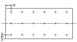
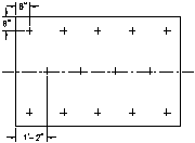
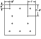
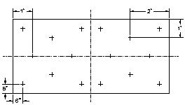
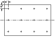
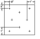
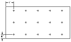
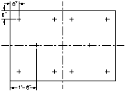
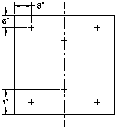
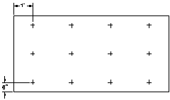
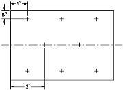
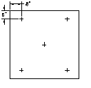
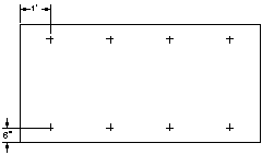
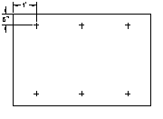
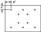
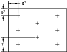
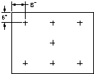
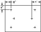
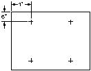
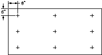
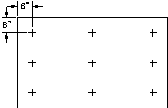
Fastener Patterns: Various Board Sizes
NOTE: Fastener locations are for optimum uplift resistance. Fasteners may be located within 50 mm (2") of position shown in diagrams in any direction.
| 1' x 2' | 3' x 5' |
|---|---|
| 9 Fasteners | 9 Fasteners |
 |
|
NOTE: Fastener locations are for optimum uplift resistance. Fasteners may be located within 50 mm (2") of position shown in diagrams in any direction.
Minimum Nail Fasteners
| Insulation Board Size | Field | Perimeter | Corner |
|---|---|---|---|
| 600 mm x 1200 mm (2'x4') | 5 | 5 | 6 |
| 600 mm x 2400 mm (2'x8') | 8 | 10 | 12 |
| 900 mm x 1200 mm (3'x4') | 6 | 8 | 10 |
| 1200 mm x 1200 mm (4'x4') | 6 | 8 | 10 |
| 1200 mm x 1800 mm (4'x6') | 8 | 10 | 14 |
| 1200 mm x 2400 mm (4'x8') | 12 | 16 | 18 |
When conventionally adhered roof assemblies are installed, (adhered, hot asphalt mopped, torched, etc.), all insulation must be mechanically fastened to all nailable decks including steel, with exceptions as per (reference here). The upper layer or overlay in a multiple-layer insulation application does not require mechanical fastening. The exception is for slopes exceeding 1:12 (1" in 12") or steeper - in those cases, the upper layer must be fastened.
When using multiple layers of plastic foam insulation the layers shall be mechanically fastened, whenever possible, as if they are a single layer. Alternately, when the use of mechanical fasteners is not feasible, or multiple layered assemblies require mechanical fastening of the base layer only, or decks are constructed of non-nailable materials (concrete,) polyurethane foam adhesives may be utilized to adhere insulation layers to one another, to other insulations, or substrates. Only polyurethane foam adhesives that are specifically listed as acceptable by the insulation manufacturer may be used. Extruded polystyrene insulation must have planed faces (removal of smooth surface) when adhered with polyurethane foam adhesive.
Additional Requirements The upper layer or overlay in a multiple-layer insulation application does not require mechanical fastening. If mechanical fastening to concrete decking is required proprietary concrete fasteners and plates must be used.
Acceptable nail types: Shank-and-head or head-plate nails with minimum 25 mm (1")nominal head size. Head-plate nails with solidly attached plate to ensure plate cannot slide down on shank.
Cavity deck or T Deck may be defined as either nailable or non-nailable, depending on profile and deflection.
Nailing is permitted on wood decks only where insulation thickness does not exceed 50 mm (2"). Nails with a minimum 25 mm (1") head size or greater are required for insulation and overlay boards fastened to wood decks. Nails to be placed a maximum 600 mm (24") o/c in each direction and be of sufficient length to penetrate the underlying sheathing a minimum of 20 mm (3/4") or in the case of plywood, completely through the sheathing.
When insulation and or cover boards are installed under mechanically fastened membrane systems the membrane manufacturer’s tested and approved fastener layout patterns shall be followed. In addition, the minimum number of fasteners with plates for insulation and or cover boards, under mechanically fastened membranes, shall be six (6) fasteners for 1200mm x 2400mm (4ft. x 8ft,) board sizes and four (4) fasteners for all other smaller board sizes.
For all adhered asphaltic membranes, ie: hot asphalt, torch welded, or cold adhesive applied roof assemblies:
On all heat sensitive insulations (polystyrene; extruded and expanded), an overlay consisting of two layers of acceptable cover board is to be installed when using hot asphalt as an adhesive, or where the cover board is less than 1/2" in thickness on torch applied assemblies.
Two layer system: Fasten the first layer of cover board, offsetting the joints from those of the insulation. Tape the joints before applying the second layer, offsetting the joints from both layers below. Alternatively, all layers of cover board and insulation may be fastened as a group.
Single layer system: Flame protection under or over the cover board is required. Seal over all board joints and wall transitions with membrane manufacturer's approved self-adhered membrane tape. Alternatively, a full layer of minimum No. 25 asphalt coated fiberglass base sheet conforming to CAN/CSA-A123.16-04 (R2009), Type II or No. 30 non-perforated felt conforming to CSA A123.3-05 (R2010) may be used under the cover board.
Composite board insulations with factory applied base sheets that utilize self-adhering seams for flame protection, are mechanically attached over decks listed by the membrane manufacturer, and specifically accepted by RGC, may be installed as a single layer overlay board over heat sensitive insulations.
Heat Insensitive Insulation Only: In the case of heat insensitive insulations, one layer of acceptable overlay board is required. For hot asphalt applied roof assemblies the insulation is to be mechanically fastened before an acceptable overlay board is fully mopped to the insulation. Alternatively, manufacturers proprietary insulation adhesives may be used to adhere accepted overlay boards to insulations. When hot asphalt or adhesives are not used in a roof assembly accepted insulation and overlay board(s) may, as a group, be mechanically fastened directly to nailable decks including steel.
3.4 Wind Uplift Design and CSA A123.21
| Qualifying for a RoofStar Guarantee |
|---|
| To qualify for a RoofStar Guarantee, and to comply with the Guarantee Standards in this Manual, mechanically attached insulated membrane systems must be fastened according to each manufacturer’s tested specifications conforming to CSA A123.21 Standard (latest edition) for assembly wind ratings. |
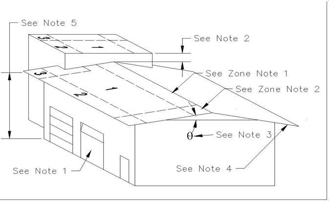
The roof area is divided into three areas (zones). The perimeter area is defined as 10% of the building width or 40% of the building height, whichever is less. In no case will perimeter area be less than 2.0 m (7'). The field area is defined as the remaining area after the perimeter is calculated. When the roof height is:• greater than 18 m (60’) and low-slope (slope is 2:12 or less) or• less than 18 m (60’) and pitched (slope is greater than 2:12), Perimeter fastening along the entire eave will be enhanced to corner requirements. The corner area is defined by the perimeter in both directions at the corners. In no case will the corner area be less than 2.0 m x 2.0 m (7’ x7’).
For corner enhancement of roofs in high wind locations (higher than 100 mph) or for roofs above 60’ refer to Section (reference here).
3.4.1 ZONE AREAS
- Field Area:
- Zone 1
- Perimeter Area:
- Zone 2. The area at the edge of the roof. Perimeter width shall be defined as the lesser of 10% of the building width or 40% of the building height, but not less than 2.0 m (7’).
- Corner Area:
- Zone 3. Corner area dimensions shall be equal to perimeter width in both directions and not less than 2.0 m (7’).
3.4.2 NOTES
- Wall Openings:
- Contribute to increased wind uplift on roof area. Included in RGC fastener requirements.
- Adjoining Roof Height:
- Where less than 900 mm (3’), design as if one roof. Where 900 mm (3’) or greater, upper roof should be designed as separate roof.
- Roof Slope:
- Wind uplift changes at all Zones as slope changes.#Overhangs:
- Overhangs increase the wind uplift in some roof locations. Included in RGC fastener requirements.
- Roof Height:
- On slopes under 10° (2’ in 12’ nominal) use eave height for roof height. On slopes 10° (2’ in 12’ nominal) or greater, use mean average roof height (mid-point).
3.4.3 ZONE NOTES
- Ridge:
- On slopes over 10° (1:6 or 2" in 12", nominal) the ridge field area should be upgraded to Zone 2 (perimeter).
- Ridge Corner:
- On slopes over 10° (1:6 or 2" in 12", nominal) and on buildings 18 m (60’) high or less ridge perimeter at the corners should be upgraded to Zone 3 (corner).
Regional Wind Speed
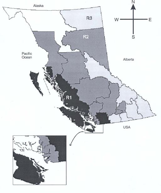
The province of British Columbia is divided into three regions:
- Region 1 - High wind region
- Region 2 - Moderate wind region
- Region 3 - Low wind region
Note:
- Region 1 is located near the coast while most of Region 3 is located at the inland area.
3.4.4 Additional Requirements
The upper layer or overlay in a multiple-layer insulation application does not require mechanical fastening. If mechanical fastening to concrete decking is required proprietary concrete fasteners and plates must be used.
Acceptable nail types: Shank-and-head or head-plate nails with minimum 25 mm (1")nominal head size. Head-plate nails with solidly attached plate to ensure plate cannot slide down on shank.
Cavity deck or T Deck may be defined as either nailable or non-nailable, depending on profile and deflection.
Nailing is permitted on wood decks only where insulation thickness does not exceed 50 mm (2"). Nails with a minimum 25 mm (1") head size or greater are required for insulation and overlay boards fastened to wood decks. Nails to be placed a maximum 600 mm (24") o/c in each direction and be of sufficient length to penetrate the underlying sheathing a minimum of 20 mm (3/4") or in the case of plywood, completely through the sheathing.
When insulation and or cover boards are installed under mechanically fastened membrane systems the membrane manufacturer’s tested and approved fastener layout patterns shall be followed. In addition, the minimum number of fasteners with plates for insulation and or cover boards, under mechanically fastened membranes, shall be six (6) fasteners for 1200mm x 2400mm (4ft. x 8ft,) board sizes and four (4) fasteners for all other smaller board sizes.
For all adhered asphaltic membranes, ie: hot asphalt, torch welded, or cold adhesive applied roof assemblies:
On all heat sensitive insulations (polystyrene; extruded and expanded), an overlay consisting of two layers of acceptable cover board is to be installed when using hot asphalt as an adhesive, or where the cover board is less than 1/2" in thickness on torch applied assemblies.
Two layer system: Fasten the first layer of cover board, offsetting the joints from those of the insulation. Tape the joints before applying the second layer, offsetting the joints from both layers below. Alternatively, all layers of cover board and insulation may be fastened as a group.
Single layer system: Flame protection under or over the cover board is required. Seal over all board joints and wall transitions with membrane manufacturer's approved self-adhered membrane tape. Alternatively, a full layer of minimum No. 25 asphalt coated fiberglass base sheet conforming to CAN/CSA-A123.16-04 (R2009), Type II or No. 30 non-perforated felt conforming to CSA A123.3-05 (R2010) may be used under the cover board.
Composite board insulation with factory applied base sheets that utilize self-adhering seams for flame protection, are mechanically attached over decks listed by the membrane manufacturer, and specifically accepted by RGC, may be installed as a single layer overlay board over heat sensitive insulation. For fastener spacing requirements, see the Table below under 6.4.1 Mechanical Fastening.
Heat Insensitive Insulation Only: In the case of heat insensitive insulations, one layer of acceptable overlay board is required. For hot asphalt applied roof assemblies the insulation is to be mechanically fastened before an acceptable overlay board is fully mopped to the insulation. Alternatively, manufacturers proprietary insulation adhesives may be used to adhere accepted overlay boards to insulations. When hot asphalt or adhesives are not used in a roof assembly accepted insulation and overlay board(s) may, as a group, be mechanically fastened directly to nailable decks including steel.
3.5 Adhering Insulation
When foam plastic insulation is adhered with a compatible adhesive in a roof assembly, the insulation board size shall be a maximum 1200 mm (4') in any direction.
Only RGC accepted overlay boards may be installed by the back mop and flop application method over heat sensitive foam plastic insulation boards. Heat insensitive insulation boards, (e.g. Polyisocyanurate) are not permitted to be installed with this method.
Asphalt or paraffin-impregnated coated fibreboard roof insulation, used as an insulation overlay board must be asphalt-coated on the top and bottom surface (minimum coated two-sides) when adhered (in a roof assembly) with hot asphalt or asphaltic based adhesive.
Proprietary adhesive applied insulation/overlay board membrane systems accepted and installed in the RoofStar Guarantee Program shall conform to the CSA A123.21-10 Standard test method for the dynamic wind uplift resistance of adhesive attached membrane roofing systems and/or the Factory Mutual I-90 Listing for adhesive attached assemblies.
The roof system must be as per the complete tested assembly and a calculation for the building wind load requirements using the Wind-RCI calculator or RoofNav as applicable be submitted with project documents.

