
Difference between revisions of "Draft CD 19"
Difference between revisions of "Draft CD 19"
(→WORK INCLUDED) |
|||
| Line 1: | Line 1: | ||
| − | { | + | |
| − | | | + | |
| − | + | {{DISPLAYTITLE:<span style="position: absolute; clip: rect(1px 1px 1px 1px); clip: rect(1px, 1px, 1px, 1px);">{{FULLPAGENAME}}</span>}} | |
| + | __NOTOC__ | ||
| + | |||
| + | <big><big>Division D - Construction Details</big></big> | ||
| + | <hr> | ||
| + | <big><big><big><big><big>TPO | Membrane Termination A (Wall) ([[TPO_Roof_Systems_Standard#10.3.2.3._General_Application_Requirements_for_Perimeters_and_Walls | Article 10.3.2.3.]])</big></big></big></big></big> | ||
| + | {{Template:Construction Details Header}} | ||
<div class="panel panel-success"> | <div class="panel panel-success"> | ||
| − | <div class="panel-heading"><big>''' | + | <div class="panel-heading"><big>'''TPO Details'''</big></div> |
<div class="panel-body"> | <div class="panel-body"> | ||
<div class="col-md-6"> | <div class="col-md-6"> | ||
<div style="text-align:center; vertical-align:center"> | <div style="text-align:center; vertical-align:center"> | ||
| − | [[File: | + | <br> |
| + | [[File:10.3.2.3.-PVC-A.png |class=img-responsive | link=https://rpm.rcabc.org/images/f/fc/10.3.2.3.-PVC-A.png]] | ||
| + | :Drawing NTS | ||
</div> | </div> | ||
| − | </div><!-- COL-MD | + | </div><!-- COL-6-MD --> |
<div class="col-md-6"> | <div class="col-md-6"> | ||
=== WORK INCLUDED === | === WORK INCLUDED === | ||
| − | ;(1) [[ | + | |
| − | ;( | + | ;(1) [[TPO Roof Systems Standard#PART_6|<big>Air/Vapour Control Layers</big>]]: |
| − | ;( | + | :As specified by the ''Design Authority'' and installed to provide continuity for optimal control. |
| − | ;( | + | ;(2) [[TPO Roof Systems Standard#PART_7|<big>Insulation</big>]]: |
| − | ;( | + | :Installed in keeping with Section 7.3. Multiple layering illustrated; layers must be offset and staggered at least 304.8 mm (12”) in each direction. |
| − | ;( | + | ;(3) [[TPO Roof Systems Standard#PART_8|<big>Insulation Overlay Panel</big>]]: |
| − | ;( | + | :Required for fully adhered membrane systems or when overburden is specified. Panels must be offset and staggered from underlying insulation panels. |
| − | ;( | + | ;(4) [[TPO Roof Systems Standard#PART_9|<big>Field Membrane</big>]]: |
| − | + | :See Table 9.2. for permissible application methods and corresponding membrane properties. Membrane must be installed according to the requirements in Section 9.3. | |
| + | ;(5) [[TPO Roof Systems Standard#PART_10|<big>Edge Securement</big>]]: | ||
| + | :Proprietary to the membrane manufacturer. Edge securement is required, irrespective of how the membrane is applied (i.e., adhered, self-adhered, mechanically fastened). | ||
| + | ;(6) [[TPO Roof Systems Standard#PART_10|<big>Mechanical Fastening</big>]]: | ||
| + | :Edge securement must be anchored to the roof structure to prevent membrane movement. | ||
| + | ;(7) [[TPO Roof Systems Standard#PART_10|<big>Primer or Adhesive</big>]]: | ||
| + | :Proprietary to the membrane manufacturer. Primer may be required for self-adhered membranes; adhesive is required for all other applications. All membranes applied to the vertical substrate must be fully adhered. | ||
| + | ;(8) [[TPO Roof Systems Standard#PART_10|<big>Membrane Flashing</big>]]: | ||
| + | :May be run continuously up the vertical substrate from the field or installed as separate flashing (see membrane manufacturer requirements). Membrane shall be carried up the vertical substrate at least 203.2 mm (8”) above the ''finished roof system surface'', plus at least 76.2 mm (3”) for wall control layer overlap. In regions where heavy snow accumulation is possible, or to accommodate future roof membrane replacement, membrane should be carried at least 304.8 mm (12”) up the vertical substrate. | ||
| + | ;(9) [[TPO Roof Systems Standard#PART_10|<big>Rigid Support for Through-wall Flashing (optional)</big>]]: | ||
| + | :Where the ''wall'' is insulated on the exterior side of the structure, ''continuity'' of air and vapour controls must be protected from future damage during roof replacement. This can be done by securing a suitable membrane receiver panel against the insulation. The panel must be permanently affixed to the structure through the insulation. During replacement of the roof membrane, membrane flashing may be removed from the receiver panel without disturbing the insulation and control layers. In this way, material waste is also reduced. | ||
| + | |||
| + | :Where the membrane may not easily separate from its receiver during roof replacement, a second panel (not illustrated) can be screw-fastened to the first. During replacement, both the membrane and the secondary panel may be removed together, simplifying membrane replacement. | ||
| + | ;(10) [[TPO Roof Systems Standard#PART_10|<big>Membrane Flashing Substrate</big>]]: | ||
| + | :''Continuity'' of the water-resistive barrier means it must pass through the insulation assembly installed on the exterior side of the wall structure. To do that, a membrane flashing passes through the insulation where the ''roof system'' terminates. Blocking or another suitable support (i.e., hat track) is necessary to support the membrane and its linear metal flashing carrier. Wood blocking illustrated. | ||
| + | ;(10) [[TPO Roof Systems Standard#PART_10|<big>Through-wall Flashing</big>]]: | ||
| + | :A self-adhered membrane is used to transition from the ''wall'' to the ''roofing assembly'', providing a continuous drainage path for water. Secure the ''linear metal flashing'' to the support underneath (see Item 9 or 10 above). | ||
| + | |||
| + | :Note that the water resistive barrier membrane from the ''wall'' (installed by others – see Related Work below) overlaps the through-wall flashing (installed by the ''Contractor'') and is supported by a metal flashing with drip edge, to direct water from the wall to the roof surface. | ||
=== RELATED WORK BY OTHERS === | === RELATED WORK BY OTHERS === | ||
| − | ;(A) ''' | + | ;(A) [[TPO Roof Systems Standard#PART_2|<big>Acceptable Deck</big>]] |
| + | :Illustrated deck is representative. See Sub-section 2.1.5. for acceptable ''deck'' types and conditions. | ||
| + | ;(B) [[TPO Roof Systems Standard#PART_2|<big>Wall Structure</big>]] | ||
| + | :Illustrated wall is representative. Wall control layers (i.e., water resistive barrier) must overlap ''roofing system'' to achieve ''continuity''. See Sub-section 2.1.7. for wall conditions. | ||
| + | ;(C) <big>Wall System Finish</big> | ||
| + | :Illustrated system is representative and shows water-resistive barrier overlapping roof membrane (See above, Item 8). | ||
| + | |||
</div><!-- COL-6-MD --> | </div><!-- COL-6-MD --> | ||
</div><!-- PANEL BODY --> | </div><!-- PANEL BODY --> | ||
</div><!-- PANEL --> | </div><!-- PANEL --> | ||
| − | '''NOTE''': | + | '''NOTE''': See the [[TPO Roof Systems Standard | '''TPO Roof Systems Standard''']] for additional requirements. |
<hr> | <hr> | ||
| + | [[TPO Roof System Details|<i class="fa fa-chevron-circle-left fa" ></i> Back to ''TPO Roof System Details'']] | ||
| − | [[ | + | [[Main Page | <i class="fa fa-home fa"></i> Home]] |
| − | |||
| − | |||
| − | + | {{Template:RPM Page Footer with Copyright and Current Date}} | |
Revision as of 22:12, 23 February 2024
Division D - Construction Details
TPO | Membrane Termination A (Wall) ( Article 10.3.2.3.)
| Notice to Reader | |
| Images used in a Construction Detail are representative and not prescriptive, and are not necessarily drawn to scale. They are intended to support the related Standard (Ref. Division A, Article 2.2.1.2.).
The reader may link to the related Article in the detail title, or link to the Standard as it relates to a specific element in the detail. All hyperlinks are displayed blue text. | |
TPO Details
- Drawing NTS
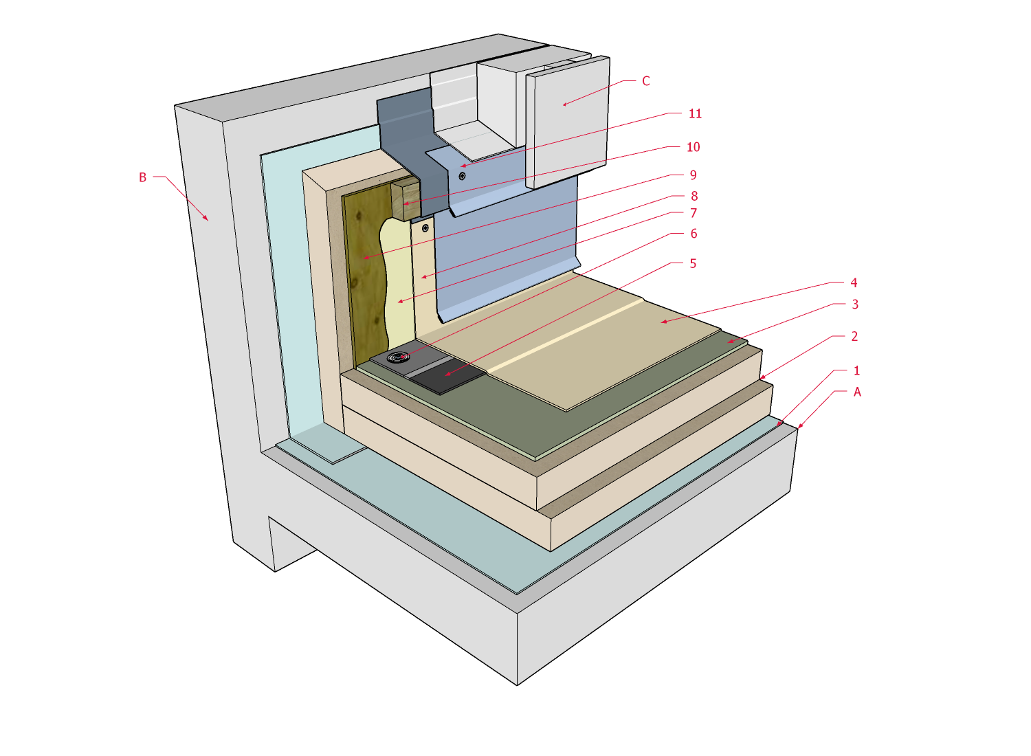
1 WORK INCLUDED
- (1) Air/Vapour Control Layers
- As specified by the Design Authority and installed to provide continuity for optimal control.
- (2) Insulation
- Installed in keeping with Section 7.3. Multiple layering illustrated; layers must be offset and staggered at least 304.8 mm (12”) in each direction.
- (3) Insulation Overlay Panel
- Required for fully adhered membrane systems or when overburden is specified. Panels must be offset and staggered from underlying insulation panels.
- (4) Field Membrane
- See Table 9.2. for permissible application methods and corresponding membrane properties. Membrane must be installed according to the requirements in Section 9.3.
- (5) Edge Securement
- Proprietary to the membrane manufacturer. Edge securement is required, irrespective of how the membrane is applied (i.e., adhered, self-adhered, mechanically fastened).
- (6) Mechanical Fastening
- Edge securement must be anchored to the roof structure to prevent membrane movement.
- (7) Primer or Adhesive
- Proprietary to the membrane manufacturer. Primer may be required for self-adhered membranes; adhesive is required for all other applications. All membranes applied to the vertical substrate must be fully adhered.
- (8) Membrane Flashing
- May be run continuously up the vertical substrate from the field or installed as separate flashing (see membrane manufacturer requirements). Membrane shall be carried up the vertical substrate at least 203.2 mm (8”) above the finished roof system surface, plus at least 76.2 mm (3”) for wall control layer overlap. In regions where heavy snow accumulation is possible, or to accommodate future roof membrane replacement, membrane should be carried at least 304.8 mm (12”) up the vertical substrate.
- (9) Rigid Support for Through-wall Flashing (optional)
- Where the wall is insulated on the exterior side of the structure, continuity of air and vapour controls must be protected from future damage during roof replacement. This can be done by securing a suitable membrane receiver panel against the insulation. The panel must be permanently affixed to the structure through the insulation. During replacement of the roof membrane, membrane flashing may be removed from the receiver panel without disturbing the insulation and control layers. In this way, material waste is also reduced.
- Where the membrane may not easily separate from its receiver during roof replacement, a second panel (not illustrated) can be screw-fastened to the first. During replacement, both the membrane and the secondary panel may be removed together, simplifying membrane replacement.
- (10) Membrane Flashing Substrate
- Continuity of the water-resistive barrier means it must pass through the insulation assembly installed on the exterior side of the wall structure. To do that, a membrane flashing passes through the insulation where the roof system terminates. Blocking or another suitable support (i.e., hat track) is necessary to support the membrane and its linear metal flashing carrier. Wood blocking illustrated.
- (10) Through-wall Flashing
- A self-adhered membrane is used to transition from the wall to the roofing assembly, providing a continuous drainage path for water. Secure the linear metal flashing to the support underneath (see Item 9 or 10 above).
- Note that the water resistive barrier membrane from the wall (installed by others – see Related Work below) overlaps the through-wall flashing (installed by the Contractor) and is supported by a metal flashing with drip edge, to direct water from the wall to the roof surface.
2 RELATED WORK BY OTHERS
- (A) Acceptable Deck
- Illustrated deck is representative. See Sub-section 2.1.5. for acceptable deck types and conditions.
- (B) Wall Structure
- Illustrated wall is representative. Wall control layers (i.e., water resistive barrier) must overlap roofing system to achieve continuity. See Sub-section 2.1.7. for wall conditions.
- (C) Wall System Finish
- Illustrated system is representative and shows water-resistive barrier overlapping roof membrane (See above, Item 8).
NOTE: See the TPO Roof Systems Standard for additional requirements.
Back to TPO Roof System Details
© RCABC 2024
No reproduction of this material, in whole or in part, is lawful without the expressed permission of the RCABC Guarantee Corp.