
Difference between revisions of "Draft CD 4"
Difference between revisions of "Draft CD 4"
(→WORK INCLUDED) |
|||
| Line 28: | Line 28: | ||
;(1) [[SBS Roof Systems Standard#PART_10|'''Control Joint (Roof Divider)''']]: | ;(1) [[SBS Roof Systems Standard#PART_10|'''Control Joint (Roof Divider)''']]: | ||
| − | :Typically framed with dimensional lumber and plywood on site by the Contractor, or by others (as specified). Insulated control joint shown in Drawing ( | + | :Typically framed with dimensional lumber and plywood on site by the Contractor, or by others (as specified). Insulated control joint shown in Drawing (A). See [[SBS_Roof_Systems_Standard#10.1.6.2. Control Joints (Roof Dividers) | Article 10.1.6.2.]] concerning permissible design heights for control joints. |
;(2) [[SBS Roof Systems Standard#PART_10|'''Base sheet membrane flashing''']]: | ;(2) [[SBS Roof Systems Standard#PART_10|'''Base sheet membrane flashing''']]: | ||
:Fully envelope the control joint to ensure water-tightness on all sides. The base membrane flashing also separates metal cap flashing (when specified) from any organic substrates (plywood, dimensional lumber). | :Fully envelope the control joint to ensure water-tightness on all sides. The base membrane flashing also separates metal cap flashing (when specified) from any organic substrates (plywood, dimensional lumber). | ||
| Line 34: | Line 34: | ||
:Installed as required in Part 10 and applied as the second or third of a multi-ply membrane system, providing required coverage above the ''finished roof system surface'' (note that the required minimum coverage may be reduced when the joint is fully enveloped with two plies of membrane flashing (see illustration). | :Installed as required in Part 10 and applied as the second or third of a multi-ply membrane system, providing required coverage above the ''finished roof system surface'' (note that the required minimum coverage may be reduced when the joint is fully enveloped with two plies of membrane flashing (see illustration). | ||
| − | :When the height of the control joint exceeds 203.2 mm (8”) (Ref. Drawing ( | + | :When the height of the control joint exceeds 203.2 mm (8”) (Ref. Drawing (A)), no fewer than two plies of sheet membrane flashing shall be carried up at least 203.2 mm above the ''finished roof system surface''. |
;(3) [[SBS Roof Systems Standard#PART_13|'''Metal Cap Flashing''']]: | ;(3) [[SBS Roof Systems Standard#PART_13|'''Metal Cap Flashing''']]: | ||
Revision as of 16:48, 31 October 2022
Division D - Construction Details
SBS | Parapet (Typical) ( Article 10.3.2.3.; Article 10.3.4.1.)
| Notice to Reader | |
| Images used in a Construction Detail are representative and not prescriptive, and are not necessarily drawn to scale. They are intended to support the related Standard (Ref. Division A, Article 2.2.1.2.).
The reader may link to the related Article in the detail title, or link to the Standard as it relates to a specific element in the detail. All hyperlinks are displayed blue text. | |
SBS Details
Use arrows to scroll through related images (A, B, and C). Click any image to expand.
Drawing A
Drawing B
Drawing C
_-_A.png)
_-_B.png)
_-_C.png)
1 WORK INCLUDED
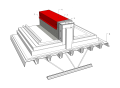
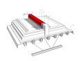
- (1) Control Joint (Roof Divider)
- Typically framed with dimensional lumber and plywood on site by the Contractor, or by others (as specified). Insulated control joint shown in Drawing (A). See Article 10.1.6.2. concerning permissible design heights for control joints.
- (2) Base sheet membrane flashing
- Fully envelope the control joint to ensure water-tightness on all sides. The base membrane flashing also separates metal cap flashing (when specified) from any organic substrates (plywood, dimensional lumber).
- (3) Cap sheet membrane flashing
- Installed as required in Part 10 and applied as the second or third of a multi-ply membrane system, providing required coverage above the finished roof system surface (note that the required minimum coverage may be reduced when the joint is fully enveloped with two plies of membrane flashing (see illustration).
- When the height of the control joint exceeds 203.2 mm (8”) (Ref. Drawing (A)), no fewer than two plies of sheet membrane flashing shall be carried up at least 203.2 mm above the finished roof system surface.
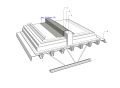
- (3) Metal Cap Flashing
- Required only when the low control joint (less than 203.2 mm (8”) in height) is not fully enveloped with at least two plies of sheet membrane flashing. Cap flashing must be designed and installed as required in Part 13.
- Note that the cap flashing is sloped at least 2% (mono slope illustrated) when the width of the flashing exceeds 101.6 mm (4”) (Ref. Article 13.1.3.6., “Cap Flashing, Counter-flashing, and Reglet Flashing”).
- Fasteners used to secure metal flashing must be at least 88.9 mm (3-1/2”) above the finished roof system surface.
2 RELATED WORK BY OTHERS
- (A) Acceptable deck
NOTE: See the Standard for additional requirements.
Back to "SBS" Roof System Details
© RCABC 2024
No reproduction of this material, in whole or in part, is lawful without the expressed permission of the RCABC Guarantee Corp.