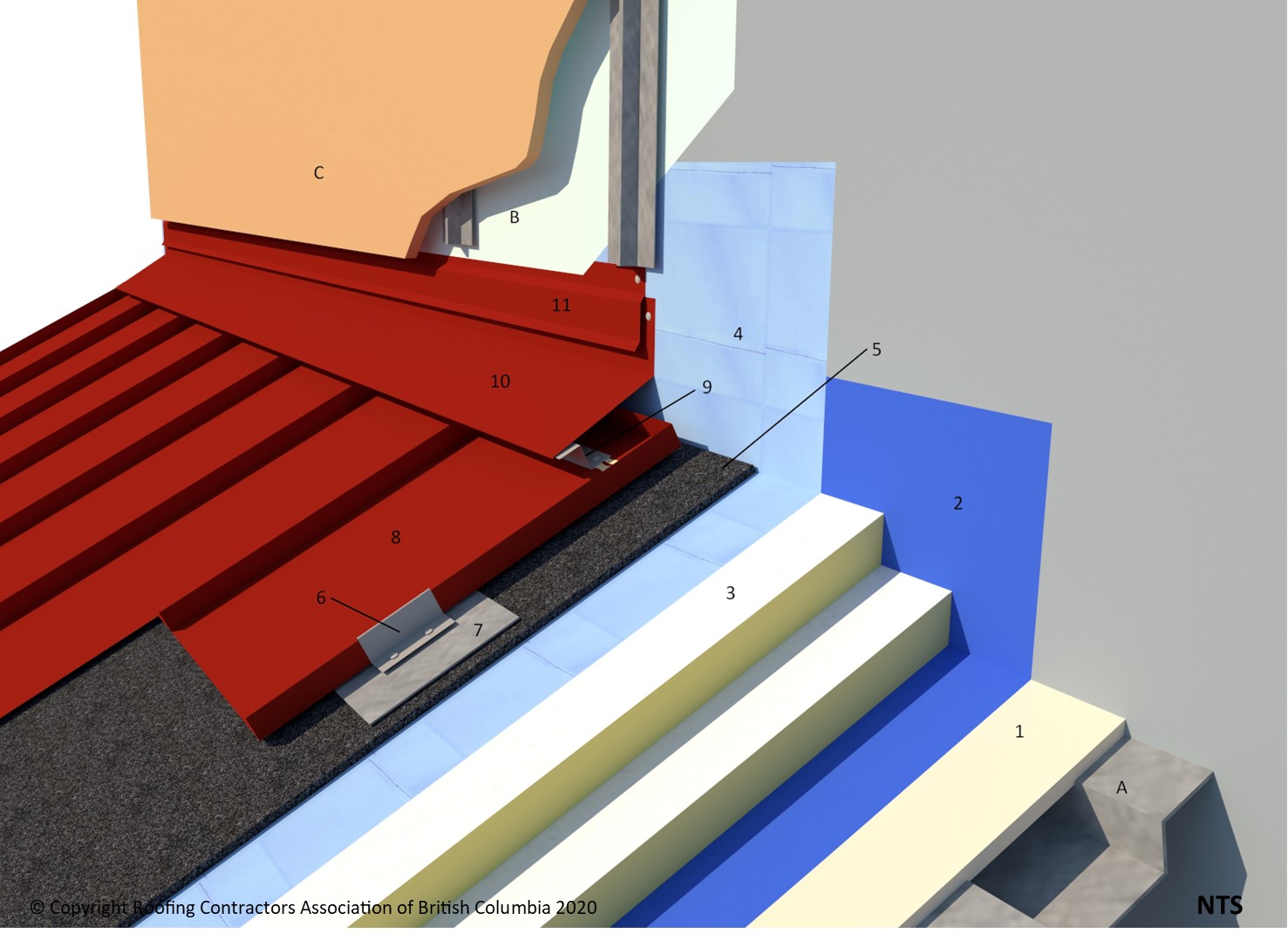
ASM Roof-Wall Connection (Head-wall)
ASM Roof-Wall Connection (Head-wall)
Division D - Construction Details
ASM | Roof-Wall Connection (Head-wall) ( Article 10.3.2.3.)
| Notice to Reader | |
| Images used in a Construction Detail are representative and not prescriptive, and are not necessarily drawn to scale. They are intended to support the related Standard (Ref. Division A, Article 2.2.1.2.).
The reader may link to the related Article in the detail title, or link to the Standard as it relates to a specific element in the detail. All hyperlinks are displayed blue text. | |
ASM Details
1 WORK INCLUDED
- (1) Deck overlay
- Required over some deck surface to provide a solid or continuous substrate for roof system materials. Here, a deck overlay is provided to support a continuous AVB layer.
- (2) Underlayment
- Applicable for all Architectural Sheet Metal systems. For slopes less than 1:3, the entire roof slope must be covered with a self-adhered underlayment.
- (3) Insulation
- Installed with offset side and end joints.
- (4) Vapour-permeable separation membrane
- Installed over insulation and required on all insulated Architectural Sheet Metal Roof Systems. The material must be located between the insulation and metal panels/ventilation material (see 8.1.2 Design).
- (5) Ventilation material
- A ventilation space is required on slopes less than 1:3; entangled mesh (shown) may be used as void fill. The ventilation space facilitates drying as condensation forms on the underside of the metal panels.
- (6) Metal Panel Clip
- Installed to metal roof panel manufacturer's printed instructions.
- (7) Bearing plate
- Used to support clips and distribute dead and live loads when direct contact with a solid substrate is not possible.
- (8) Architectural metal roof panel
- (9) 'Z'-Closure
- Set in acceptable sealant and secured with compatible, non-corrosive, flat head fasteners.
- (10) Sheet Metal Flashing
- Hooked to 'Z'-Closure and fastened to wall with non-corrosive, flat head fasteners 300 mm (12") o/c or preformed foam closures set in acceptable sealant with high domed gasketed cladding type screws at each standing rib.
- (11) Metal Counter Flashing
- Must extend behind wall system and wall control layers. Stucco stops are not considered to be a counter flashing.
2 RELATED WORK BY OTHERS
- (A) Acceptable deck
- (B) Wall control layers
- must be positively lapped with roof materials and flashings, to maintain continuity across systems.
- (C) Wall cladding
NOTE: See the Standard for additional requirements.
Back to ASM Roof System Details
© RCABC 2026
RoofStarTM is a registered Trademark of the RCABC.
No reproduction of this material, in whole or in part, is lawful without the expressed permission of the RCABC Guarantee Corp.


