
Difference between revisions of "Draft CD 2"
Difference between revisions of "Draft CD 2"
| (2 intermediate revisions by the same user not shown) | |||
| Line 6: | Line 6: | ||
<big><big>Division D - Construction Details</big></big> | <big><big>Division D - Construction Details</big></big> | ||
<hr> | <hr> | ||
| − | <big><big><big><big><big>EPDM | | + | <big><big><big><big><big>EPDM | Metal Edge Termination ([[EPDM_Roof_Systems_Standard#10.3.4.2._Low_Profile_Edge | Article 10.3.4.2.]])</big></big></big></big></big> |
{{Template:Construction Details Header}} | {{Template:Construction Details Header}} | ||
<div class="panel panel-success"> | <div class="panel panel-success"> | ||
| Line 14: | Line 14: | ||
<div style="text-align:center; vertical-align:center"> | <div style="text-align:center; vertical-align:center"> | ||
<br> | <br> | ||
| − | [[File:10.3.2.3.-EPDM- | + | [[File:10.3.2.3.-EPDM-B.png|class=img-responsive | link=https://rpm.rcabc.org/images/c/c6/10.3.2.3.-EPDM-B.png]] |
:Drawing NTS | :Drawing NTS | ||
</div> | </div> | ||
| Line 22: | Line 22: | ||
=== WORK INCLUDED === | === WORK INCLUDED === | ||
| − | ;(1) | + | ;(1) <big>Suitable field substrate</big>: |
| − | : | + | :May be the [[EPDM Roof Systems Standard#PART_2| roof ''deck'']] or [[SBS Roof Systems Standard#PART_5 |''deck'' overlay]] (if an uninsulated system), or [[SBS Roof Systems Standard#PART_8| insulation and an overlay]] (if ''conventionally insulated''). |
| − | + | ;(2) <big>Primer or adhesive</big>: | |
| − | + | :For self-adhered or adhered membranes, as required by the ''manufacturer''. | |
| − | + | ;(3) [[EPDM Roof Systems Standard#PART_9|<big>Field membrane</big>]]: | |
| − | + | :Carried continuously over the outside edge at least 50.8 mm (2”) downward, or 50.8 mm past any cold joint. | |
| − | + | ;(4) [[EPDM Roof Systems Standard#PART_9|<big>Sealant</big>]]: | |
| − | + | :Applied on membrane, beneath metal edge flashing. | |
| − | + | ;(4) <big>Sealant or mastic</big>: | |
| − | + | :Applied on membrane, beneath metal edge flashing. | |
| − | ;( | + | ;(5) <big>[[EPDM Roof Systems Standard#PART_13| Metal edge flashing</big>]] (flush with roof surface): |
| − | + | :Fasteners spaced no more than 203.2 mm (8”) on the top face in two offsetting rows. | |
| − | + | :A hemmed drip edge (shown) is required (Refer to Article 13.2.2.1. for fabrication requirements). | |
| − | : | + | ;(7) [[EPDM Roof Systems Standard#PART_10|<big>Edge sealant</big>]]: |
| − | ;( | ||
| − | : | ||
| − | ;( | ||
| − | : | ||
| − | |||
| − | : | ||
| − | ;( | ||
| − | : | ||
| − | ;( | ||
| − | |||
| − | |||
| − | |||
=== RELATED WORK BY OTHERS === | === RELATED WORK BY OTHERS === | ||
| − | ;(A) [[EPDM Roof Systems Standard#PART_2|<big> | + | ;(A) [[EPDM Roof Systems Standard#PART_2|<big>Structural Roof Deck</big>]] |
| − | : | + | :Generic and representative only. |
| − | ;(B) [[EPDM Roof Systems Standard# | + | ;(B) [[EPDM Roof Systems Standard#PART_10|<big>Roof edge substrate</big>]] |
| − | : | + | :Wood blocking, required for conventionally insulated roofs. |
| − | ;(C) <big>Wall | + | ;(C) <big>Wall assembly</big> |
| − | : | + | :Generic and representative only. |
</div><!-- COL-6-MD --> | </div><!-- COL-6-MD --> | ||
| Line 69: | Line 57: | ||
[[Main Page | <i class="fa fa-home fa"></i> Home]] | [[Main Page | <i class="fa fa-home fa"></i> Home]] | ||
| − | {{ | + | {{Template:RPM Page Footer with Copyright and Current Date}} |
Latest revision as of 21:58, 27 October 2025
Division D - Construction Details
EPDM | Metal Edge Termination ( Article 10.3.4.2.)
| Notice to Reader | |
| Images used in a Construction Detail are representative and not prescriptive, and are not necessarily drawn to scale. They are intended to support the related Standard (Ref. Division A, Article 2.2.1.2.).
The reader may link to the related Article in the detail title, or link to the Standard as it relates to a specific element in the detail. All hyperlinks are displayed blue text. | |
EPDM Details
- Drawing NTS
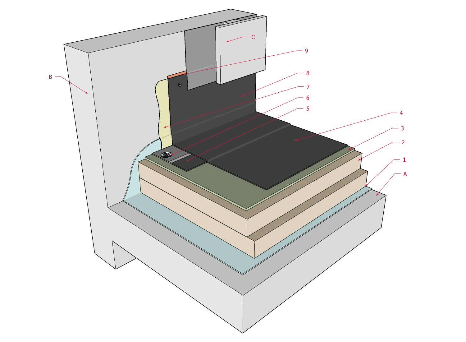
1 WORK INCLUDED
- (1) Suitable field substrate
- May be the roof deck or deck overlay (if an uninsulated system), or insulation and an overlay (if conventionally insulated).
- (2) Primer or adhesive
- For self-adhered or adhered membranes, as required by the manufacturer.
- (3) Field membrane
- Carried continuously over the outside edge at least 50.8 mm (2”) downward, or 50.8 mm past any cold joint.
- (4) Sealant
- Applied on membrane, beneath metal edge flashing.
- (4) Sealant or mastic
- Applied on membrane, beneath metal edge flashing.
- (5) Metal edge flashing (flush with roof surface):
- Fasteners spaced no more than 203.2 mm (8”) on the top face in two offsetting rows.
- A hemmed drip edge (shown) is required (Refer to Article 13.2.2.1. for fabrication requirements).
- (7) Edge sealant
2 RELATED WORK BY OTHERS
- (A) Structural Roof Deck
- Generic and representative only.
- (B) Roof edge substrate
- Wood blocking, required for conventionally insulated roofs.
- (C) Wall assembly
- Generic and representative only.
NOTE: See the EPDM Roof Systems Standard for additional requirements.
Back to EPDM Roof System Details
© RCABC 2026
RoofStarTM is a registered Trademark of the RCABC.
No reproduction of this material, in whole or in part, is lawful without the expressed permission of the RCABC Guarantee Corp.