
SBS Roof Systems Standard
SBS Roof Systems Standard
Contents
- 1 Accept Terms Of Use
- 2 Part 1 - General
- 2.1 Section 1.1. Design
- 2.1.1 1.1.1. General
- 2.1.1.1 1.1.1.1. Scope
- 2.1.1.2 1.1.1.2. Coverage and Limitations
- 2.1.1.3 1.1.1.3. References
- 2.1.1.4 1.1.1.4. Defined Terms
- 2.1.1.5 1.1.1.5. Reserved
- 2.1.1.6 1.1.1.6. Objectives
- 2.1.1.7 1.1.1.7. Responsibility for Design
- 2.1.1.8 1.1.1.8. Pre-Design Requirements
- 2.1.1.9 1.1.1.9. Suitability of Design
- 2.1.2 1.1.2. Guarantee Requirements
- 2.1.3 1.1.3. All Systems
- 2.1.4 1.1.4. Replacement and Alterations
- 2.1.5 1.1.5. Reserved
- 2.1.1 1.1.1. General
- 2.2 Section 1.2. Reserved
- 2.3 Section 1.3. Application
- 2.1 Section 1.1. Design
- 3 Part 2 - Supporting Structures: Decks and Walls
- 4 Part 3 - Securing the Roof Assembly
- 4.1 Section 3.1. Design
- 4.2 Section 3.2. Materials
- 4.3 Section 3.3. Application
- 5 Part 4 - Materials
- 6 Part 5 - Deck and Wall Overlays
- 7 Part 6 - Air and Vapour Controls
- 7.1 Section 6.1. Design
- 7.1.1 6.1.1 General
- 7.1.2 6.1.2. Guarantee Term Requirements
- 7.1.3 6.1.3. All Systems
- 7.1.3.1 6.1.3.1. Responsibility for Design
- 7.1.3.2 6.1.3.2. Continuity of Control Layers
- 7.1.3.3 6.1.3.3. Use of Air Control Materials
- 7.1.3.4 6.1.3.4. Use of Vapour Control Materials
- 7.1.3.5 6.1.3.5. High-humidity Building Interiors
- 7.1.3.6 6.1.3.6. Membrane Roofs Installed on Vented Wood-Frame Structures
- 7.2 Section 6.2. Materials
- 7.3 Section 6.3. Application
- 7.1 Section 6.1. Design
- 8 Part 7 - Insulation
- 8.1 Section 7.1. Design
- 8.2 Section 7.2. Materials
- 8.3 Section 7.3. Application
- 9 Part 8 - Insulation Overlays
- 9.1 Section 8.1. Design
- 9.2 Section 8.2. Materials
- 9.3 Section 8.3. Application
- 10 Part 9 - Roof Field (Membrane Systems)
- 10.1 Section 9.1. Design
- 10.2 Section 9.2. Materials
- 10.3 Section 9.3. Application
- 10.3.1 9.3.1. Guarantee Term Requirements
- 10.3.2 9.3.2. All Systems
- 10.3.2.1 9.3.2.1. Preparation of Substrate
- 10.3.2.2 9.3.2.2. Preparation of Roofing Materials
- 10.3.2.3 9.3.2.3. General Requirements for Membrane Application
- 10.3.2.4 9.3.2.4. Cold and Inclement Weather Application
- 10.3.2.5 9.3.2.5. Securement on Slopes
- 10.3.2.6 9.3.2.6. Membrane Seams
- 10.3.2.7 9.3.2.7. Protection of Membranes
- 10.3.2.8 9.3.2.8. Transitions with Water-shedding Systems
- 10.3.2.9 9.3.2.9. Walkways
- 10.3.3 9.3.3. Membrane Application Methods
- 10.3.3.1 9.3.3.1. Self-adhered and Cold-processed Membranes
- 10.3.3.2 9.3.3.2. Mechanically Attached Membranes
- 10.3.3.3 9.3.3.3. Hot Asphalt-adhered Membranes
- 10.3.3.4 9.3.3.4. Torch-applied Membranes
- 10.3.3.5 9.3.3.5. Liquid Membranes (Field Application)
- 10.3.3.6 9.3.3.6. Membranes Laminated to Insulation Overlays
- 10.3.4 9.3.4. Conventionally Insulated Systems
- 10.3.5 9.3.5. Uninsulated Systems
- 10.3.6 9.3.6. Protected Roof Systems
- 11 Part 10 - Perimeters and Walls
- 11.1 Section 10.1. Design
- 11.1.1 10.1.1. General
- 11.1.2 10.1.2. Guarantee Term Requirements
- 11.1.3 10.1.3. All Systems
- 11.1.4 10.1.4. Perimeter Details, High Walls, and Openings
- 11.1.5 10.1.5. Reserved
- 11.1.6 10.1.6. Expansion and Control Joints
- 11.1.7 10.1.7. Intersections with Other Roof Systems
- 11.1.8 10.1.8. Alternative Approaches for Membrane Flashing
- 11.2 Section 10.2. Materials
- 11.3 Section 10.3. Application
- 11.3.1 10.3.1. Guarantee Term Requirements
- 11.3.2 10.3.2. All Systems
- 11.3.3 10.3.3. Additional Requirements for Membrane Flashing
- 11.3.4 10.3.4. Perimeter Details, High Walls, and Openings
- 11.3.5 10.3.5. Reserved
- 11.3.6 10.3.6. Expansion and Control Joints
- 11.3.7 10.3.7. Intersections with Other Roof Systems
- 11.3.8 10.3.8. Alternative Approaches to Sheet Membrane Flashing
- 11.1 Section 10.1. Design
- 12 Part 11 - Drainage
- 12.1 Section 11.1. Design
- 12.2 Section 11.2. Materials
- 12.3 Section 11.3. Application
- 12.3.1 11.3.1. Guarantee Term Requirements
- 12.3.2 11.3.2. All Systems
- 12.3.3 11.3.3. Drains and Membrane Gutters
- 12.3.3.1 11.3.3.1. Drain Sumps
- 12.3.3.2 11.3.3.2. General Requirements for Cast-iron Roof Drains
- 12.3.3.3 11.3.3.3. Cast-iron Drains Installed with Lead Flashing
- 12.3.3.4 11.3.3.4. Cast-iron Drains Installed with Membrane Flashing
- 12.3.3.5 11.3.3.5. Cast-iron Roof Drain Retrofitting (Replacement Roofing)
- 12.3.3.6 11.3.3.6. Flanged Insert-type Roof Drains
- 12.3.3.7 11.3.3.7. Scuppers and Overflows
- 12.3.3.8 11.3.3.8. Membrane Gutters
- 13 Part 12 - Penetrations and Curbs
- 13.1 Section 12.1. Design
- 13.1.1 12.1.1. General
- 13.1.2 12.1.2. Guarantee Term Requirements
- 13.1.3 12.1.3. All Systems
- 13.1.3.1 12.1.3.1. General Requirements for Penetrations
- 13.1.3.2 12.1.3.2. Galvanized Penetration Flashings
- 13.1.3.3 12.1.3.3. Separation Between Details
- 13.1.3.4 12.1.3.4. Curbs, Sleepers, and Equipment Pads
- 13.1.3.5 12.1.3.5. Protection of Roof Membranes
- 13.1.3.6 12.1.3.6. Railings, Ladders, and Other Attached Structures
- 13.2 Section 12.2. Materials
- 13.3 Section 12.3. Application
- 13.3.1 12.3.1. Guarantee Term Requirements
- 13.3.2 12.3.2. All Systems
- 13.3.2.1 12.3.2.1. General Requirements for Flashing Penetrations
- 13.3.2.2 12.3.2.2. Galvanized Penetration Flashings
- 13.3.2.3 12.3.2.3. Separation Between Penetration Flashings
- 13.3.2.4 12.3.2.4. Curbs, Sleepers, and Equipment Pads
- 13.3.2.5 12.3.2.5. Alternative Approaches to Membrane Flashing
- 13.3.2.6 12.3.2.6. Liquid Membrane Flashing
- 13.3.2.7 12.3.2.7. Railings, Ladders, and Other Attached Structures
- 13.3.2.8 12.3.2.8. Sealant Pockets
- 13.1 Section 12.1. Design
- 14 Part 13 - Linear Metal Flashing
- 14.1 Section 13.1. Design
- 14.1.1 13.1.1. General
- 14.1.2 13.1.2. Guarantee Term Requirements
- 14.1.3 13.1.3. All Systems
- 14.1.3.1 13.1.3.1. Scope and Function
- 14.1.3.2 13.1.3.2. Information Required in Specifications
- 14.1.3.3 13.1.3.3. Securement
- 14.1.3.4 13.1.3.4. Gauge, Dimension Limitations, and Seams
- 14.1.3.5 13.1.3.5. Fit and Finish
- 14.1.3.6 13.1.3.6. Cap Flashing, Counter-flashing, and Reglet Flashing
- 14.1.3.7 13.1.3.7. Intersections with Other Assemblies
- 14.2 Section 13.2. Materials
- 14.3 Section 13.3. Application
- 14.1 Section 13.1. Design
- 15 Part 14 - The Roof as a Platform
- 15.1 Section 14.1. Design
- 15.1.1 14.1.1. General
- 15.1.2 14.1.2. Guarantee Term Requirements
- 15.1.3 14.1.3. All Systems
- 15.1.3.1 14.1.3.1. Coverage and Limitations
- 15.1.3.2 14.1.3.2. Loads
- 15.1.3.3 14.1.3.3. Securement of Roof Coverings, Structures, and Equipment
- 15.1.3.4 14.1.3.4. Design for Repairs and Renewal
- 15.1.3.5 14.1.3.5. Roof Membranes
- 15.1.3.6 14.1.3.6. Membrane Protection
- 15.1.3.7 14.1.3.7. Membrane Integrity Testing and Electronic Leak Detection
- 15.1.3.8 14.1.3.8. Drainage
- 15.1.3.9 14.1.3.9. Filter Fabric
- 15.1.3.10 14.1.3.10. Gravel
- 15.1.3.11 14.1.3.11. Wearing Surfaces
- 15.1.3.12 14.1.3.12. Vegetated Roof Systems
- 15.1.3.13 14.1.3.13. Structures and Equipment
- 15.2 Section 14.2. Materials
- 15.2.1 14.2.1. Material Properties
- 15.2.1.1 14.2.1.1. Field and Flashing Membranes
- 15.2.1.2 14.2.1.2. Membrane Protection
- 15.2.1.3 14.2.1.3. Reserved
- 15.2.1.4 14.2.1.4. Drainage and Water Retention Materials
- 15.2.1.5 14.2.1.5. Insulation and Insulation Overlays
- 15.2.1.6 14.2.1.6. Filter Fabric
- 15.2.1.7 14.2.1.7. Decorative Gravel
- 15.2.1.8 14.2.1.8. Pavers and Pedestals
- 15.2.1 14.2.1. Material Properties
- 15.3 Section 14.3. Application
- 15.1 Section 14.1. Design
- 16 Notes to Standard
Division B - Standards
Waterproofing Roof Systems: Flexible Membranes (Polymer-modified Bituminous)
RGC Standard for SBS-modified Bitumen Membrane Roofs
This Standard is a consolidation of requirements previously published in the Roofing Practices Manual for Flexible Membrane Roofing Systems. It is comprised of fourteen (14) Parts that contain the requirements, guiding principles, recommendations and informative materials necessary for a roof to qualify for a RoofStar 5-Year Guarantee, RoofStar 10-Year Guarantee or RoofStar 15-year Guarantee. Requirements to qualify for a RoofStar 15-Year Guarantee are listed in each relevant Part under Section 1. All RoofStar 15-Year Guarantee requirements must be read together with the General Requirements for each Part in this Standard.
Notes to the Standard are hyperlinked from each Part and can be read by using the link in the Table of Contents for the Standard. Highlighted text within the body of the Standard indicates revisions made within the last twelve (12) months.
This Standard follows a specific structure, incorporates defined terms, and utilizes coloured text to denote specific meaning; this is explained in Division A, Part 2, "Structure and Organization of RPM and Standards". When the requirements in this Standard conflict with other resources found either in this Manual or in manufacturer's published instructions, the rules for Authority and Conflict in Division A, Article 2.3.1.2. shall be applied.
Readers are advised to review relevant materials that can be accessed through the hyperlinks embedded in the body of text.
First Edition: June 14, 2018
Previous Edition: November 1, 2025
Current Edition: Adopted January 20, 2026
All changes to this Standard are effective
February 1, 2026
© RCABC 2026
RoofStarTM is a registered Trademark of the RCABC.
No reproduction of this material, in whole or in part, is lawful without the expressed permission of the RCABC Guarantee Corp.
Part 1 - General
Section 1.1. Design
1.1.1. General
1.1.1.1. Scope
- The scope of this Part and the Standard shall be as described in Division A, Part 1.
- In addition to the Scope described in Division A, this Standard applies to the design and construction of roof systems that are site-built, or which may be factory fabricated, in part or in their entirety.
1.1.1.2. Coverage and Limitations
- Coverage under the RoofStar™ Guarantee shall be as described in Division A, Article 3.2.1.1. and Article 3.2.1.2.
1.1.1.3. References
- In this Standard, all references to
- the "British Columbia Building Code" (the "Building Code", or the "Code"), to municipal or regional building codes or regulations, or to other standards, presume the current edition that is in force,
- materials mean those materials expressly accepted by the Guarantor, unless stated otherwise, and
- measurements are shown in metric units first, followed by Imperial values (typically in parentheses; see Division A, Article 2.1.3.2., "Measurements").
1.1.1.4. Defined Terms
- Words that appear in italics are defined in the Glossary. Additionally, the following terms are used in this Part and the Standard:
- Design Authority means the individual or firm responsible for the issuance of project specifications and details to which the project will be bid and constructed. When a Contractor designs a project, the Contractor is deemed to be the Design Authority.
- Finished system surface means the top surface of any waterproofing or water-shedding system, inclusive of ballast or overburden.
- Grade-level waterproofing system means an insulated or uninsulated system, designed and constructed at grade with a sheet or liquid-applied membrane, to exclude water.
- Guarantor (used interchangeably with RGC) means the RCABC Guarantee Corporation, which offers the RoofStar Guarantee.
- Linear metal flashing means flashings cut and shaped from flat metal stock, to redirect water at roof perimeters and edges, or to control the flow of water in valleys and drainage spillways. Linear metal flashings also protect roof membranes from weathering and damage and provide an aesthetic finish to the waterproofing system or water-shedding system.
- Membrane system means the combination of field and flashing membranes which function together to waterproof underlying materials and systems.
- Observer means a firm or person paid by the building Owner (directly, or through the RGC), who is independent (not a member) of the RCABC, and who is accepted by the RGC to provide Quality Assurance reviews during construction and after completion of the project, according to the terms and conditions set out in RCABC policy.
- Qualified roof condition surveyor means a person trained and competent in the use and interpretation of infrared thermographic and electronic moisture scanning equipment, used in the condition assessment of a roof .
- Vegetated Roof Assembly (VRA), used interchangeably in the "RGC Standard for Vegetated Roofs" with green roof or green roofing, means a functional arrangement of interacting components, inclusive of vegetation, that is designed in conjunction with a supporting roof assembly, is intended to both grow and flourish, and is often installed on a roof to control the rate of rainwater discharged through a storm drainage system.
- Waterproofing system means a sealed, functional arrangement of primary materials constructed on roofs, plaza decks, or on grade-level slabs (with or without insulation and other related materials), to resist the transmission of liquid water through the system, including water under hydrostatic pressure.
- Water-shedding roof system means an insulated or uninsulated roof system, designed and constructed to shed water away from a structure, not to waterproof it. This type of system typically is installed on roof slopes greater than 1:4 (3” in 12”) but may be installed on slopes as low as 1:6 (2" in 12").
1.1.1.5. Reserved
1.1.1.6. Objectives
- Every roof system shall conform to the more stringent of this Standard or the Building Code or By-law having jurisdiction.
1.1.1.7. Responsibility for Design
- Each design of a roof system shall be undertaken by a person or persons qualified in the work concerned (See Article 3.1.3.1. with respect to the securement of the roof assembly).
- The Coordinating Registered Professional is responsible for ensuring the design of the vegetated roof assembly complies with all applicable building, energy, and fire codes having jurisdiction.
1.1.1.8. Pre-Design Requirements
- When a project is designed by an architectural or consulting firm (typically, this applies only to "new construction" projects), the Coordinating Registered Professional is responsible to ensure that the roof assembly design is a multi-disciplinary enterprise that aligns with the designs for structural, plumbing, mechanical, electrical, architectural, and building envelope, together with all trades whose work intersects with the Contractor’s scope of work, to minimize out-of-sequence operations that could compromise the integrity of the completed roof assembly.
- When any element of a roof system for a pre-fabricated building or building assembly is or will be installed off site , the Design Authority must consult with the RGC directly concerning RoofStar Guarantee coverage and wind load design (for further reference, see Article 3.2.1.2. in Division A of the Manual .
1.1.1.9. Suitability of Design
- The Design Authority is responsible for determining the appropriate roof assembly design and must consider (without limitation)
- the requirements of the building code having jurisdiction,
- the structural capabilities or limitations of the building,
- fire resistance and the roof class requirements for the building,
- wind loads (See Part 3 of this Standard),
- the effects of nearby structures on the roof assembly,
- the potential effects of reflected heat on the roof assembly,
- roof system aesthetics, and
- maintenance requirements, including the safety of maintenance workers.
- When the roof is intended as a platform to support a vegetated roof system, the supporting roof assembly must be suitable for that purpose (See Sentence 1.1.3.1.(2)).
- Membrane roof systems specified for uninsulated vented wood-frame roofs should be designed around the principles in Article 7.1.5.2.
1.1.2. Guarantee Requirements
1.1.2.1. RoofStar 5-Year Guarantee and RoofStar 10-year Guarantee
- To qualify for a RoofStar 5-year Guarantee or RoofStar 10-year Guarantee, all projects shall comply with the requirements in this Part.
- In addition to Sentence (1), all projects shall comply with
- the project specifications and drawings, and
- the manufacturer's published installation requirements.
1.1.2.2. RoofStar 15-Year Guarantee
- To qualify for a RoofStar 15-year Guarantee, all projects shall comply with the requirements in this Standard for a RoofStar 5-year Guarantee or RoofStar 10-year Guarantee, together with the following:
- Each project must be designed and constructed in compliance with both the RoofStar Guarantee Standards, together with the membrane manufacturer’s available 20-year System Warranty standards.
- Where enhanced roof system securement is required by the manufacturer, which may exceed the securement required in a Tested Assembly, an Assembly with Proven Past Performance or a custom-engineered securement, the project must comply with the higher securement requirements.
- On all "new construction" projects, where external access is not provided, all roofs with a field elevation greater than 7620 mm (25’) above grade must incorporate safe, appropriate access to the roof, for example by incorporating stairs and a doorway or a properly located roof hatch (Safe, appropriate access to the roof is recommended for existing buildings, to facilitate maintenance and ongoing performance reviews).
- Moisture surveys for Membrane Replacement projects must be documented and submitted in report form to the Guarantor for review and consideration prior to tender; documented testing means a moisture survey scan performed by a qualified person, and
- at least three (3) cut tests for roof areas up to 20,000 sf (200 squares), or one (1) cut test for every 2000 sf (20 squares), whichever is more,
- one (1) cut test for every 3000 sf (30 squares) of roof area that exceeds the first 20,000 sf (200 squares), or
- one (1) cut test for each small roof area measuring no more than 200 sf (2 squares).
- Membrane Replacement projects must incorporate new insulation overlays in keeping with the requirements published in Part 8, Insulation Overlays.
- Materials left in place for partial roof system replacement must be scanned for moisture (Article 1.1.4.3.).
- All roofs (new construction and replacement roofing) must be built with a minimum slope of 2% (1:50) (Article 2.1.2.2.).
- All replacement roofing must utilize crickets to enhance drainage around curbs and sleepers (Article 2.1.2.2.).
- On new construction roofs, curbs and sleepers wider/longer than 1219.2 mm (48") must incorporate crickets to improve drainage (Article 7.1.2.2.).
- An insulation overlay is required on all conventionally insulated roof systems (Article 8.1.2.2.).
- Only certain membranes will qualify for a RoofStar 15-year Guarantee (Article 9.1.2.2.).
- All drains and overflows require clamping rings, and overflows are required for each roof area (Article 11.1.2.2.).
- Enhanced penetration flashing requirements (Article 12.1.2.2.).
- Linear metal flashings must be fabricated from 24-gauge material (Article 13.1.2.2.).
1.1.2.3. Quality Control
- Notwithstanding any other requirements in this Standard, the Contractor shall
- bid the project to meet the more stringent of this Standard or the project specifications,
- bid the project to include only RGC-accepted systems and materials,
- ensure that the supporting roof assembly conforms to the requirements and limitations of Article 1.1.3.1.,
- notify the Observer at least 24 hours before construction is scheduled to start or resume (72 hours notice is required for projects further away than 100 km from the nearest "Free Zone" city location), and then daily, before work resumes,
- ensure that construction conforms to this Standard and exhibits good workmanship,
- ensure that samples, reports, shop drawings, ELD arrangements, certificates, manufacturer approvals, warranty documentation, and all other submittals are collected and provided to the Guarantor as required in Article 1.3.2.4., and
- abide by all pertinent RCABC policies.
1.1.2.4. Quality Assurance
(See Note A-1.1.2.4.)
- Notwithstanding any other requirements in this Standard, the Observer shall
- verify that the materials used in construction are accepted by the Guarantor and listed in Division C of this Manual,
- review the construction of the roof system (according to the prescribed number of observations, with consideration for the expected duration of construction) for conformance with the more stringent of
- this Standard,
- conditions and limitations in Division A of the RPM, as they apply,
- the manufacturer’s published requirements,
- the project drawings and specifications, or
- the Building Code having jurisdiction.
- review and report whether the Contractor has met the RCABC policy requirements noted in this Standard, and
- perform cut tests or other acceptable methods, whenever required, to verify that the materials and methods of construction conform to this Standard (for example, this may be required when the Contractor has completed more than 30 squares of roofing without an observation).
1.1.3. All Systems
1.1.3.1. Permitted Roof Systems
(See Note A-1.1.3.1.)
- This Standard applies to new construction, and to the partial or complete replacement of existing roofs, constructed as
- Uninsulated systems in which the membrane is bonded directly to the roof deck or an overlay, and is exposed to the weather and to sunlight,
- Conventionally insulated systems, sometimes referred to as Compact Roofs, in which the membrane is installed above insulation and other roof system materials, and is exposed to the weather and to sunlight,
- Protected roof systems, also referred to as “inverted”, in which the membrane is installed beneath other roof system or protection materials (usually insulation), and is protected from exposure to the weather and from sunlight, and
- Modified protected roof systems, which combine the functions and benefits of both a conventionally insulated system and a protected roof system, and where the membrane is protected from exposure to the weather and to sunlight.
- Where the roof is intended to support a vegetated roof system and qualify for a RoofStar Vegetated Roof Guarantee, only a new roof or a roof that is specified for a complete roof system replacement will qualify for the Guarantee (See Article 1.1.4.2. and Article 1.3.3.2. ).
1.1.3.2. Accessibility for Maintenance
- All roofs with a field elevation greater than 7620 mm (25’) above grade should incorporate access to the roof by stairs and a doorway or with a properly located roof hatch.
- Any hatch, ladder or mechanical unit should be located a sufficient distance away from the roof edge (setback zone) so that other fall protection measures are not required by those using or accessing this equipment.
- When it is not possible to situate a hatch, ladder, or mechanical unit outside the setback zone, guard rails should be designed for the roof edge to provide additional fall protection for those using or accessing such equipment.
- Each roof should be designed to provide safe access for maintenance of roof drains, corners, or mechanical equipment, where the roof is at least 3 m (10’) above the surface of the ground, or where a hazard to a person exists, should a fall be possible (this principle also applies to roof areas intended for regular occupancy); design elements to mitigate fall hazards should align with the Code having jurisdiction, and with the Workers Compensation Act Regulations, and should include
- tall parapets,
- guardrails, or
- tie-off anchors.
- Where a roof is intended to support a vegetated roof system, the roof must satisfy the design and pre-construction requirements published in the “RGC Standard for Vegetated Roofs”.
1.1.3.3. Membrane Integrity Testing
(See Note A-1.1.3.3. and Figure 1.1.3.3.-A)
- Electrical current membrane integrity testing shall conform to
- ASTM D7877, "Standard Guide for Electronic Methods for Detecting and Locating Leaks in Waterproof Membranes", or
- ASTM D8231, "Standard Practice for the Use of Low Voltage Electronic Scanning System for Detecting and Locating Breaches in Roofing and Waterproofing Membranes."
- An electrical current membrane integrity test is required when anyone other than the Contractor installs overburden, amenities, or equipment, (In this Standard, the term "electrical current membrane integrity test" means a test method that uses electrical current and electronic sensing technology to detect breaches in the membrane system).
- An electrical current membrane integrity test is required when the Contractor installs overburden, amenities, or equipment, but only when
- the total project area (footprint), inclusive of planters or other waterproofed features, exceeds 18.58 m2 (200 sf), and
- overburden, amenities, or equipment exceed 152.4 mm (6”) in depth .
- When the roof assembly supports a vegetated roof system covered by a RoofStar Guarantee, an electrical current membrane integrity test is recommended but is not required; however, when an integrity test is specified by the Design Authority, it must be carried out immediately prior to the installation of a vegetated roof system.
- An electrical current membrane integrity test must be performed by an RGC-recognized service provider listed in Division C.
- Flood testing employed as a secondary or alternative membrane integrity test is strongly discouraged for conventionally insulated roof systems because of the risk of extensive damage to system components or the building interior, and is best suited for protected roof systems (See Note A-1.1.3.3.(5)).
- If flood testing is specified, it shall be conducted prior to the installation of insulation and roof coverings, and must be executed in keeping with ASTM D5957, "Standard Guide for Flood Testing Horizontal Waterproofing Installations".
Figure 1.1.3.3.-A Electronic Integrity Testing
Forming Part of Article 1.1.3.3.
(Click to expand illustration)

1.1.3.4. Electronic Leak Detection
(See Note A-1.1.3.4.)
- Electronic Leak Detection (ELD), when specified by the Design Authority, shall conform to
- ASTM D7877, "Standard Guide for Electronic Methods for Detecting and Locating Leaks in Waterproof Membranes", or
- ASTM D8231, "Standard Practice for the Use of Low Voltage Electronic Scanning System for Detecting and Locating Breaches in Roofing and Waterproofing Membranes."
- Electronic Leak Detection (ELD) is optional for waterproofing roof systems, but strongly recommended
- for projects where multiple trades will have access to a roof that is under construction and completed, to identify breaches in the waterproofing membrane in a timely way and avoid future costly delays,
- when the roof assembly protects a sensitive occupied space (i.e., data centres, hospitals, critical infrastructure), or
- when the roof supports any type of overburden, amenities, or equipment, including a vegetated roof system.
- When Electronic Leak Detection is specified, it shall provide detection capabilities for all waterproofed surfaces, and should extend at least 50.8 mm (2") vertically from the drainage plane at
- all transitions,
- any point along the entire deck perimeter, and
- protrusions.
1.1.3.5. Hot Works
(See Note A-1.1.3.5.)
- The Design Authority may specify that the Contractor must maintain compliance with the RCABC Hot Works Program and consequently manage the Hot Works conducted on site (See Article 1.3.2.1.).
- When the project involves Hot Work, the Design Authority must either
- pre-approve alternate applications already written in this Standard or another applicable Standard published in this Manual, when the specified application is deemed to be fire-sensitive by the Contractor as part of the risk assessment process, or
- provide alternate material and application requirements in the Specification for fire sensitive locations on the project.
1.1.3.6. Variances
- When a design is unable to conform to the Standard, the Design Authority may apply to the RGC for a written Variance.
- Application for a written Variance must be made in writing (email correspondence is common), and must
- identify the project name and its civic address,
- identify the RoofStar Guarantee number (if assigned),
- identify the Contractor (if awarded),
- articulate the nature of the design problem,
- identify the RoofStar Guarantee requirement to be varied, and state the desired modification (i.e., reduce the requirement for 203.2 mm (8") to 152.4 mm (6")),
- cite the reference to which the Variance will apply (i.e., Standard name, article number, sentence number, etc.), and
- provide design drawings, photographs, and roof plans, referencing grid lines that identify or articulate the boundaries to which the Variance will be applied.
- Variances are issued by the RGC only to the Design Authority and will be distributed to the Contractor.
- A Variance may be unrestricted in its scope, or it may include one or more conditions, or a restriction in coverage, that will affect the design and construction of the project, to accommodate the varied standard, but this is at the discretion of the Guarantor.
- Variances are issued only for the project-specific issue identified in the written request, and do not constitute general permission to depart from the published requirements in this Standard, for any aspect of the same project or for future projects, designed or constructed by any other firm.
- A Variance for a vegetated roof assembly shall conform to the requirements in Article 1.1.3.6. of the “RGC Standard for Vegetated Roofs”.
1.1.4. Replacement and Alterations
(The requirements in Subsection 1.1.3., "All Systems", shall be read together with the following Articles) (See Note A-1.1.4.)
1.1.4.1. General Requirements
- Unless expressly permitted otherwise in this Standard, the design for replacement roofing shall conform to the requirements for new roofing in this Standard.
- When an in-service roof assembly is uninsulated and vented, the Design Authority should consider the potential for condensation on the underside of the deck and design the roof system replacement around the principles in Article 7.1.5.2.
1.1.4.2. Complete Roof System Replacement
- Complete roof system replacement shall conform to the general requirements in Article 1.1.4.1., unless expressly varied elsewhere in this Standard.
- Roof system replacement means the complete removal and replacement of all roof system and metal flashing materials, exclusive of the air or vapour control layers, and only new replacement materials shall be installed.
- Subject to the requirements in Part 6, "Air and Vapour Controls", the decision to reuse and repair an existing air or vapour control layer remains the responsibility of the Design Authority.
- Roof system replacement projects are eligible to qualify for a RoofStar 5-year Guarantee, RoofStar 10-year Guarantee, or a RoofStar 15-year Guarantee, subject to their respective requirements.
1.1.4.3. Partial Roof Replacement
- Partial replacement of roof systems is permitted by the Guarantor, but coverage under the Guarantee is limited to new materials supplied and installed by the Contractor.
- Retention of insulation materials in a roof system is subject to the requirements for insulation in Part 7.
- Membrane replacement, which is limited to the removal and replacement of the roof membrane and materials adhered to the membrane,
- may be specified without a written Variance from the Guarantor, and
- may qualify for a RoofStar 5-year Guarantee and RoofStar 10-year Guarantee, provided
- the Design Authority is certain the existing roof system is properly secured to the existing deck structure (See Part 3, "Securing the Roof Assembly"),
- the existing roof system is demonstrably dry and free of any wet materials (wet materials must be replaced, in order to qualify for a RoofStar Guarantee),
- the existing field membrane will be removed,
- a new insulation overlay will be supplied and installed, together with a new roof membrane,
- existing membrane flashing will be removed and replaced with new materials, and
- the design conforms to the requirements in this Standard for new roof construction.
- To qualify for a RoofStar 15-year Guarantee, membrane replacement projects must conform to the requirements of this Article and shall include the removal and replacement of the insulation overlay (Ref. Article 1.1.2.2.).
1.1.4.4. Membrane Recovering
(See Note A-1.1.4.4.)
- Recovering (installing a new membrane system over an in-service membrane system) is not a recommended practice and will limit the scope of coverage under the RoofStar Guarantee, but it is acceptable to the Guarantor only when the following conditions, in addition to any other applicable requirements published in this Article or in Article 1.3.3.4., have been satisfied :
- the in-service roof has never before been recovered (recovering is not permitted over a previously recovered roof system) ,
- the new recovering roof system conforms to the usual design, material, and construction requirements of this Standard, including wind load requirements ,
- the recovering specifications, plans, and detail drawings have been provided to, and reviewed by, the Guarantor prior to the tendering of the project ,
- the Guarantor has issued a written Variance that expressly permits recovering and outlines the conditions and limitations under which recovering may proceed, and
- the Design Authority has satisfied the submittal requirements for recovering, in this Standard .
- A recovered roof does not qualify for a RoofStar Vegetated Roof Guarantee.
- A RoofStar Guarantee issued for a recovered roof is limited strictly to the value of new roof system materials; in-service materials left in place beneath new materials are not covered by the RoofStar Guarantee.
- All membrane recovering project specifications and drawings shall reflect and conform to the construction requirements in Article 1.3.3.4.
- Before proceeding with roof recovering, the Design Authority should consider
- the requirements for moisture testing (described below),
- testing securement of materials to be left in place, and
- the potential consequences of failure for the building and its use.
- To qualify for a written Variance from the Guarantor, the Variance request (See Article 1.1.3.6.)
- must identify the type of roof system to which the Variance pertains (i.e., uninsulated, conventionally insulated, protected, or modified protected roof system),
- must indicate how the new roof system will be secured (See Part 3, "Securing the Roof Assembly"),
- must specify how the existing roof system will be physically separated from other roof areas, and
- must include the formal independent report that describes the condition of the existing roof system, and which documents results from cut tests and moisture investigation that are prerequisites for a RoofStar Guarantee.
- In-service Uninsulated and protected roof systems presented to the Guarantor in a written Variance application by the Design Authority must be
- free of blisters and breaches in the membrane,
- independently surveyed by a qualified roof condition surveyor , when they are constructed on a wood deck, using calibrated moisture detection equipment, and
- cut open and probed for moisture and deterioration by a qualified roof condition surveyor when any moisture is detected in a wood deck (the results of such investigation must be formally documented for review by the Guarantor).
- In-service Conventionally insulated and modified protected roof systems presented to the Guarantor in a written Variance application by the Design Authority must be independently surveyed by a qualified roof condition surveyor using calibrated moisture detection equipment and cut tests, and the resulting survey shall be formally documented for review by the Guarantor.
- In-service protected membrane roof systems constructed with a bituminous polymer-modified membrane system may qualify for recovering without a new overlay board, provided the in-service membrane is
- free of blisters, de-bonded membrane, damage, seam failures, or breaches ,
- independently surveyed for moisture by a qualified roof condition surveyor using calibrated moisture detection equipment ,
- cut open and probed for moisture and deterioration when any moisture is detected below the roof system (the results of such investigation must be formally documented for and reviewed by the Guarantor), and
- tested for adhesion to demonstrate that a new membrane applied to the existing membrane will remain bonded to its substrate (See Note A- 1.1.4.4.(9) ).
- In-service conventionally insulated built-up roof systems (typically constructed with felt and asphalt) shall conform to the requirements in Sentence (8) .
- In-service uninsulated or protected membrane roof systems constructed with a built-up (BUR) membrane may qualify for recovering without a new overlay board, but
- the roof deck shall be dry ,
- the membrane must be spudded clean of gravel ,
- all loose plies of felt and asphalt shall be removed and discarded ,
- the remaining in-service materials must be cut open and probed for moisture and deterioration by a qualified roof condition surveyor when any moisture is detected below the roof system in a wood deck (the results of such investigation must be formally documented for and reviewed by the Guarantor), and
- remaining layers of in-service material must be tested for adhesion to demonstrate that a new membrane applied to the existing membrane will remain bonded to its substrate (See Note A- 1.1.4.4.(9)).
- All cut test surveys performed on conventionally insulated systems
- shall be independently documented for review by the Guarantor,
- must be performed using ASTM D7636/D7636M-11, "Standard Practice for Sampling and Analysis of Modified Bitumen Roof Systems", and
- shall be no fewer than
- three (3), for roof areas up to 20,000 sf (200 squares), or one (1) for every 2,000 sf (20 squares), whichever is more,
- one (1) for every 3000 sf (30 squares) of roof area that exceeds the first 20,000 sf (200 squares), and
- one (1) for each small roof area equal to or less than 200 sf (2 squares).
- When a conventionally insulated roof system
- is structurally sloped, at least half (50%) of the required cut tests shall sample the roof in or near valleys, and near roof drains.
- is structurally flat, samples shall be taken near roof drains and in a random pattern across the roof.
- All wet material identified by either the independent moisture detection survey or through cut tests shall be specified for removal.
1.1.4.5. Tie-ins, Additions, and Alterations to Existing Roofing
- Where a new roof adjoins and ties into an existing roof, the two areas must be isolated and separated by a control joint securely attached to the structure and waterproofed in keeping with the requirements in both Article 10.1.6.2., "Control Joints (Roof Dividers)", and Part 10, "Perimeters and Walls".
- If project conditions do not allow for a curb joint, the Design Authority must submit an alternative design and obtain a written Variance from the Guarantor that permits the elimination of curb joints (see Article 1.1.3.6., "Variances"); any alternative design
- must include design specifications and construction details showing a positive water cut-off that fully isolates the existing roof system from the new roof system, and
- shall show how the new roof system will be easily distinguishable from the existing roof system.
- Repairs or renovations to an existing roof system that is not covered by a RoofStar Guarantee do not qualify for a RoofStar Guarantee (the term "renovation" means the removal and replacement of, or the application of a cover to, a portion of the roof system).
- Modifications or additions to a guaranteed roof are permissible, subject to various conditions, but must be made by a Contractor qualified to perform work under the RoofStar Guarantee Program.
1.1.5. Reserved
Section 1.2. Reserved
Section 1.3. Application
1.3.1. Reserved
1.3.2. All Systems
1.3.2.1. Hot Works: Contractor Requirements
- The Contractor must maintain the requirements of the RCABC Hot Works Program, including (without limitation)
- Insurance Coverage, wherein the limits carried on the Contractor’s policy must equal or exceed the minimum requirements set by RCABC, and coverage must be unhindered by warranties that limit or exclude coverage when Hot Works is required,
- Education and training, since workers who perform Hot Works must be trained by the Contractor and kept current with acceptable methods,
- the "British Columbia Fire Code", wherein a Fire Safety Plan, preventative methods or alternative work procedures, fire watches, and the use and placement of equipment at the project site must comply with the BC Fire Code requirements for Hot Work,
- a Fire Safety Plan, whereby
- the Contractor must assess the hazards to property and persons and produce a written Fire Safety Plan prior to the start of work, and
- the Fire Safety Plan must be kept on the project site and must be kept current until the project is completed,
- RoofStar Guarantee Standards, to which the Contractor must conform, at each juncture where the interface of different membranes applications constitutes part of the Fire Safety Plan,
- a Fire Watch, in which the Contractor must, as part of the Fire Safety Plan, conduct a fire watch
- that complies with the "British Columbia Fire Code",
- is assigned to competent, trained personnel using suitable equipment, including the use of a hand-held infrared thermometer, and
- is documented in a written fire watch log, and
- Hot Works Notification, wherein the Contractor shall notify the project authority or the AHJ, as and when required, that Hot Works will be performed.
1.3.2.2. Workmanship
(See Note A-1.3.2.2.)
- The Contractor must take reasonable measures to protect the project from damage by the weather, during and at the completion of the project.
- Open penetrations and flashings must be temporarily sealed off from the weather, even when other trades are responsible to make a permanent seal or install overlapping materials (See Article 4.2.1.1.).
1.3.2.3. Contractor Qualifications
- Supervision and installation of a RoofStar-guaranteed waterproofing roof system may be conducted only by established employees of the Contractor, and every project must be supervised by a Journeyperson employee who holds a valid ticket.
- A Journeyperson may supervise a maximum of three (3) apprentices and/or three (3) labourers (Ref. RCABC Policy A-248).
1.3.2.4. Contractor Submittals
- The Guarantor must receive from the Contractor, prior to construction of the project and to document the roof system record,
- a Tested Assembly report supplied or endorsed by a manufacturer, including documentation of the substitution of any materials identified in that test report,
- a letter in support of an Assembly with Proven Past Performance, as required in Article 3.1.4.3.(2), or
- a custom-engineered system for securing the roof assembly.
- The Contractor shall submit to the Guarantor, before a RoofStar Guarantee is issued, any and all required samples, reports, shop drawings, ELD arrangements, certificates, manufacturer approvals, or warranty documentation (required for a RoofStar 15-year Guarantee).
1.3.3. Replacement and Alterations
(The requirements in Subsection 1.3.2., "All Systems", shall be read together with the following Articles)
1.3.3.1. General Requirements
- Unless expressly permitted otherwise in this Standard, all replacement roofing shall conform to the requirements for new roofing in this Standard.
1.3.3.2. Complete Roof System Replacement
- See the requirements throughout this Standard, which apply to both new construction and replacement of a roof system.
1.3.3.3. Partial Roof Replacement
- See the requirements throughout this Standard, which apply to both new construction and replacement of a roof membrane.
1.3.3.4. Membrane Recovering
(See Article 1.1.4.4.)
- Recovering shall not proceed unless permitted by a written Variance issued by the Guarantor prior to the tendering of the project .
- All wet material identified by either the independent moisture detection survey or through cut tests shall be removed in the course of construction.
- When recovering any in-service roof waterproofed with sheet membrane, the membrane must be
- clean and free of debris, gravel, blisters, or damage, and
- cut through at the perimeter change in plane to relieve any tension or distortions in the membrane .
- When recovering uninsulated systems,
- deteriorated wood decks must be repaired with new material of like kind and quality; a new roof system shall not be installed on a compromised deck, and
- the in-service field and flashing membranes must be overlaid with a mechanically attached, inorganic moisture-resistant insulation overlay board acceptable to the Guarantor, secured to conform to the requirements in Part 3.
- When recovering conventionally insulated systems,
- the in-service membrane must be
- cut through in a grid pattern measuring no larger than 6m x 6m (approximately 20' x 20'), and
- cut through around the perimeter of the roof area, no more than 0.2 m (8") from the edge.
- the in-service field and perimeter flashing membranes must be overlaid with a mechanically attached, inorganic moisture-resistant insulation overlay board acceptable to the Guarantor, secured to conform to the requirements in Part 3 .
- the in-service membrane must be
- When an in-service conventionally insulated roof system is insulated with heat-sensitive insulation, the existing membrane must first be overlaid with at least one layer of 50.8 mm (2”) heat-resistant insulation, and then overlaid with a mechanically attached, inorganic moisture-resistant insulation overlay board acceptable to the Guarantor, secured to conform to the requirements in Part 3 .
- When recovering a protected membrane roof system, an in-service polymer-modified bituminous sheet membrane system may be directly covered with a new membrane, but only when the Guarantor has granted permission in writing through a Variance .
- In-service built-up roof systems (typically constructed with felt and asphalt) must be spudded clean of gravel, and any loose plies shall be removed .
- New membrane system materials must be properly secured to the underlying roof assembly.
- All membrane recovering projects must incorporate only new
- strip-in flashings for roof penetrations (Ref. Part 12),
- roof drains (cast-iron roof drains in usable condition are exempted from this requirement; see Article 11.3.3.2.), and
- linear metal flashings (Ref. Part 13).
1.3.3.5. Tie-ins, Additions, and Alterations to Existing Roofing
- Where a new roof adjoins and ties into an existing roof, the two areas must be isolated and separated by a curb joint securely attached to the structure and waterproofed in keeping with the requirements for control joints ( Article 10.1.6.2. and Article 10.3.6.2.).
- If the Design Authority has obtained from the Guarantor a written Variance that permits the elimination of curb joints, the new roof system must be fully isolated from the existing roof system with a positive water cut-off that renders the new roof system easily distinguishable from the existing roof system.
1.3.3.6. Repairs and Modifications
- When a roof system that is covered by an active (unexpired) RoofStar Guarantee has been damaged or otherwise requires repairs, work shall conform to the specifications of the material manufacturers, and to the requirements in this Standard, with respect to (without limitation)
- the securement of new materials ( Part 3),
- deck or wall overlays ( Part 5),
- continuity of air and vapour controls ( Part 6),
- thermal resistance and insulation overlays ( Part 7 and Part 8),
- membranes ( Part 9),
- membrane flashing ( Part 10),
- drains ( Part 11),
- penetrations and curbs ( Part 12), and
- linear metal flashings ( Part 13).
- Modifications to an existing roof system covered by an active (unexpired) RoofStar Guarantee, including (without limitation) the addition of new curbs, drains, or penetrations, shall conform to all the requirements in this Standard, or as otherwise stated.
1.3.4. Reserved
Part 2 - Supporting Structures: Decks and Walls
(See Note A-2)
Section 2.1. Design
2.1.1. General
2.1.1.1. Scope
- The scope of this Part and the Standard shall be as described in Division A, Part 1.
2.1.1.2. Defined Terms
(See Figure 2.1.1.2.-A)
- Words that appear in italics are defined in the Glossary. Additionally, the following terms are used in this Part:
- Common Slope means a slope 1:3 (4” in 12”, or 18 degrees), up to and including 1:1 (12” in 12”, or 45 degrees).
- Deck overlay means a panel material secured to the supporting deck, to render the deck surface suitable for the installation of roofing materials.
- Extreme Slope means a slope greater than 21:12 (21” in 12”, or 84 degrees).
- Flat means a slope less than 1:6 (2” in 12”, or 9 degrees).
- Low Slope means a roof with a slope 1:6 (2" in 12", or 9 degrees, up to but less than 1:3 (4” in 12”, or 18 degrees).
- Sheathing means a rigid panel material secured directly onto framing.
- Steep Slope means a slope greater than 1:1 (12” in 12”, or 45 degrees) up to and including 21:12 (21” in 12”, or 84 degrees).
- Supporting deck ("deck") means the "structural surface to which a roof system is applied" (adapted from ASTM D1079-18 Standard Terminology Relating to Roofing and Waterproofing).
- Wall means a structural or non-structural element in a building that vertically separates space. Walls may separate the outside environment from the interior conditioned space of a building, or they may separate one or more interior spaces from each other (adapted from ASTM E631-15, "Standard Terminology of Building Constructions").
- Wall overlay means a panel material secured to the surface of a wall, to render it suitable for the installation of roofing or wall cladding materials.
Figure 2.1.1.2.-A Roof Slope
Forming Part of Article 2.1.1.2.
(Click to expand illustration)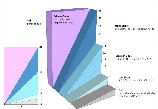

2.1.2. Guarantee Term Requirements
2.1.2.1. RoofStar 5-year Guarantee and RoofStar 10-year Guarantee
- To qualify for a RoofStar 5-year Guarantee or RoofStar 10-year Guarantee, all projects shall comply with the requirements in this Part.
2.1.2.2. RoofStar 15-Year Guarantee
- To qualify for a RoofStar 15-year Guarantee, all projects shall comply with the requirements in this Part for a RoofStar 5-year Guarantee or RoofStar 10-year Guarantee, and shall (for replacement roofs)
- be designed with a minimum slope of 2% (1/4” in 12”), measured on the primary sloped planes of the roof, and
- incorporate crickets at curbs and sleepers that impede drainage or are wider or longer than 1219.2 mm (48”).
2.1.3. All Systems
2.1.3.1. General Requirements for Roof Slope
(See Note A-2.1.3.1.)
- The Design Authority must design the slope of a roof to achieve proper drainage and must take into consideration the anticipated deflection and settlement of the structure, which may interfere with drainage.
- While good drainage is desirable but not always perfectly achievable, and roof waterproofing systems generally are not affected by standing water, each project design should incorporate sufficient slope to move water off the roof surface.
- "Sufficient slope", which is subject to conditions that permit evaporation, shall mean that no standing water remains on the roof surface after a reasonable interval following a rainfall (See Note A-2.1.3.1.(4)).
- Roof slope should be increased beyond the minimums published in this Standard when local climate conditions, such as rainfall frequency or severity, result in ongoing or significant ponding conditions (see Article 2.1.3.2. and Article 2.1.3.3. for minimum requirements).
- Drainage (slope toward plumbing drains) should be achieved (in descending order of best practices) with
- four-way slope to drain,
- two-way slope to drain, in combination with crickets between drains,
- slope to a common valley, or to gutters, or
- positive sloping valleys to drains (highly recommended).
- The use of drain sumps, designed to isolate collected water for the drain, is highly recommended, but sloping the perimeters of a sump is not required (See also Article 11.1.3.1., "Principles of Design").
2.1.3.2. Roof Slope for New Construction
- All new construction roofs must be designed and built with a slope of no less than 2% (1/4” in 12”), measured on the primary sloped planes of the roof.
- When the slope of the primary plane of drainage
- is less than 6% (3/4" in 12"), it must be covered with a 2-ply membrane roof system.
- is equal to or greater than 6% (3/4" in 12"), it may be covered with a single-ply membrane roof system.
2.1.3.3. Roof Slope for Replacement Roofing
- Replacement roof systems may qualify for a RoofStar 5-year Guarantee or RoofStar 10-year Guarantee without correcting poor drainage, though the elimination of ponding (standing water) is strongly recommended.
2.1.3.4. Deck Condition and Suitability for Roofing
- The Code having jurisdiction prevails in all cases except where it is exceeded by the requirements published in this Standard.
- Notwithstanding the requirements in this Standard, the RoofStar Guarantee does not cover the supporting deck material or its attachment to the building structure, which is the responsibility of the Design Authority and the building contractor.
- The supporting deck must be dimensionally stable, resist deflection from dead and live loads, and must be capable of accommodating roof system component movement.
- Walls, parapets, curbs, blocking, and penetrations should be constructed or placed by other trades prior to the commencement of roofing work.
2.1.3.5. Drainage Around Obstructions
- Curbs that span 2438.4 mm (96") or more when measured perpendicular to roof slope, across the direction of drainage, should be designed with a cricket to divert water around the curb.
2.1.4. Reserved
2.1.5. Roof Decks
2.1.5.1. Steel Roof Decks
(See Note A-2.1.5.1.) (See also Part 9 and Part 10 for substrate preparation requirements)
- Steel decks must be acceptable to the manufacturer and must conform to either
- ASTM Standard Specification A653 / A653M, "Standard Specification for Steel Sheet, Zinc-Coated (Galvanized) or Zinc-Iron Alloy-Coated (Galvannealed) by the Hot-Dip Process": Structural (Physical) Quality, minimum Grade 33, with a design thickness of 22-gauge (0.759 mm) or greater and a minimum zinc coating designation Z275, or
- ASTM Standard Specification A792 / A792M, "Steel Sheet, Aluminum-Zinc Alloy-Coated by the Hot-Dip Process": General Requirements, minimum Grade 33, with a design thickness of 22-gauge (0.759 mm) or greater and a minimum aluminum-zinc alloy coating designation AZ150.
2.1.5.2. Concrete Roof Decks
(See Note A-2.1.5.2.)
- Cast-in-place and precast concrete decks must cure for at least 28 days before receiving an adhered roof membrane ("adhered", as it is used in this requirement, means fully or intermittently bonding any membrane to the deck with an adhesive, hot asphalt (bitumen), or heat), but this limitation may be reduced if
- both the building envelope engineer and the manufacturer expressly permit membrane application within the first 28 days after pouring, and
- their respective signed letters of permission are furnished to the Guarantor forthwith, to be included with the project record.
- Shotcrete-formed concrete decks are not an acceptable substrate for the application of sheet membranes.
2.1.5.3. All Wood Roof Decks
(See Note A-2.1.5.3.)
- Wood decks
- must conform to the material requirements of the Code (see "British Columbia Building Code", Division B, Part 9, Article 9.23.16.2.. "Material Standards"),
- shall be free of loose knots or cracks,
- shall have a moisture content acceptable to the manufacturer (for self-adhered or adhered membranes, moisture content shall not exceed 19%; Ref. Canadian Wood Council, "Moisture and Wood"), and
- shall be secured to other supporting structural elements of the building in keeping with the published requirements of the Code having jurisdiction; specifying the structural suitability of fasteners is the responsibility of the Design Authority.
- Differential edge movements or deflection exceeding 1/360 of the span must be prevented
- by constructing the deck with tongue-and-groove plywood, and supporting the non-grooved edges with joists or solid blocking, or
- by supporting butt joints at unsupported edges with solid blocking.
- All wood board decks to which a membrane will be directly applied must be covered with a properly secured, suitable overlay to
- ensure the integrity of the membrane, and
- protect membranes from wood sap or deck surface irregularities and protruding fasteners.
- Mass timber wood decks do not require an overlay unless specified by the manufacturer.
- Securement of overlaid sheathing shall conform to the requirements for wood decks in this Part.
- All types of wood decks should be roofed promptly after installation.
- Wood roof decks that are uninsulated and vented may be subject to deterioration from condensation and therefore the roof assembly should be designed around the principles in Article 7.1.5.2.
2.1.5.4. Plywood Roof Decks
- Plywood panels should conform to CSA 0121, “Douglas Fir Plywood”, CSA 0151, “Canadian Softwood Plywood”, or CSA 0153, “Poplar Plywood”, but in any event must conform to the requirements published in the Code having jurisdiction (See Note A-2.1.5.4.(1)).
- All plywood decks (notwithstanding the minimum requirements for plywood used to overlay mass timber and wood board decks; see Article 2.1.5.5., Article 2.1.5.6., and Article 2.1.5.7.) shall be constructed to conform to the "British Columbia Building Code" for either Part 3 or Part 9 buildings, and shall be
- at least 12.7 mm (1/2”) thick, unless exceeded by the specified securement design (Ref. Part 3, "Securing the Roof Assembly"),
- free of loose knots and cracks, which are considered defects and must be covered with sheet metal, mechanically fastened in place,
- securely fastened to roof framing, and installed so that the surface grain (plywood) runs at right angles to the roof framing,
- properly gapped between panels, and
- fully supported along all panel edges.
- When a plywood deck is intended to support a protected roof system and a vegetated roof system,
- the deck and any vertical planes that contact the vegetated roof system should be pressure-treated tongue-and-groove plywood at least 19.05 mm (3/4”) thick, but when the existing deck and adjoining wall surfaces are untreated wood, they should be overlaid with no less than one layer of an RGC-accepted deck overlay panel listed in Division C of this Manual (See Note A-2.1.5.1. Suitability of Roof Deck in the "RGC Standard for Vegetated Roofs"), and
- the Design Authority shall be responsible to calculate the anticipated live and dead loads of the system and design suitable approaches to mitigate deflection.
2.1.5.5. Mass Timber Roof Decks
(See Note A-2.1.5.5.)
- Mass timber decks, which include cross-laminated timbers (CLT), nail-laminated timbers (NLT), dowel-laminated timbers (DLT), and traditional glue-laminated timbers (Glulam), are acceptable to the Guarantor and do not require an overlay, but when an overlay is required by the manufacturer it must be plywood conforming to the material requirements in Article 5.2.1.1.
- A mass timber deck that will support a vegetated roof system may be overlaid with a vapour permeable membrane, followed by screw-fastened marine-grade T&G plywood at least 19.05 mm (3/4”) thick, to which the roof system may be applied.
2.1.5.6. Non-veneered Panel Roof Decks
- Non-veneered wood decks are only suitable when the grade
- has been listed as the deck material in a tested assembly using the CSA A123.21 test method, or
- is overlaid with plywood having a minimum thickness of 12.7 mm (1/2”) and secured to the structure (joists or trusses) (See Note A-2.1.5.6.).
2.1.5.7. Wood Board Roof Decks
- Wood board decks should be of sound seasoned lumber, properly secured to the supporting structure.
- Wood board decks (including decks constructed with shiplap lumber) to which an uninsulated membrane roof system will be installed must be overlaid with an acceptable overlay conforming to Article 5.2.1.1., to render the deck suitable for roofing.
2.1.6. Reserved
2.1.7. Walls
(See Note A-2.1.7.)
2.1.7.1. General
- Wall surfaces must be clean, dry, and smooth, suitable for the application of roof system materials.
- Wood or steel-stud walls must be sheathed with a material suitable for adhering membranes and securing metal flashings; when sheathing is unsuitable, it must be overlaid with an accepted wall overlay.
- Sheathing is considered a wall surface for the purpose of this Standard.
- Wall surfaces suitable for receiving waterproofing materials must extend beyond the maximum installed height of the waterproofing, but in any event must be installed at least 203.2 mm (8”) above the finished system surface (For wall overlays, refer to Article 5.2.1.3.).
- Indirect connections between walls and roofs require a control joint (See Note A-10.1.6.2.).
2.1.8. Electrical Cables and Boxes
(See Note A-2.1.8. concerning electrical systems, fire and shock hazards, and Rule 12-022 of the Canadian Electrical Code, Part I)
2.1.8.1. New Construction
- Electrical cables, raceways or boxes shall not be installed within a roof assembly (Figure 2.1.8.1.-A).
- Electrical cables, raceways or boxes shall not be installed on the underside of a roof assembly, unless
- the supporting deck structure equals or exceeds 76.2 mm (3”) in thickness (Figure 2.1.8.1.-B), or
- the cables, raceways or boxes are installed and supported so there is a separation of not less than 38.1 mm (1-1/2") measured between the underside of the roof assembly and the electrical installation (Figure 2.1.8.1.-C).
- Notwithstanding either (1) and (2), cables or raceways shall be permitted to pass through a roof assembly for connection to electrical equipment installed on the roof, provided that the passage through the roof is a part of the roof assembly design.
- Electrical cables installed above the roof assembly should be elevated to permit proper support, roof maintenance and future replacement roofing (Figure 2.1.8.1.-D).
Figure 2.1.8.1.-A
Prohibited Installation of
Electrical Conduit
Forming Part of Sentence 2.1.8.1.(1)
(Click to expand)Figure 2.1.8.1.-B
Roof Decks and Electrical Conduit
Installation
Forming Part of Clause 2.1.8.1.(2)(1)
(Click to expand)


Figure 2.1.8.1.-C
Minimum Separation Between Roof Assembly
and Electrical Conduit
Forming Part of Clause 2.1.8.1.(2)(2)
(Click to expand)Figure 2.1.8.1.-D
Electrical Conduit Elevated Above
Roof Assembly
Forming Part of Sentence 2.1.8.1.(4)
(Click to expand)


2.1.8.2. Roof Replacement and Alterations
- If existing electrical cables or boxes do not conform to the requirements in Article 2.1.8.1., the Design Authority must consider the attachment of the roof system above the electrical system, and the requirements set out in Part 3, "Securing the Roof Assembly".
- The Design Authority should
- specify protection of existing electrical cables and boxes (a 4.76 mm (3/16”) steel plate may be used to minimize the possibility of fastener penetration and cutter damage, but protection plates may interfere with mechanical fasteners used to secure the roof system against wind uplift, even for future replacement roofing), and
- provide the building owner with detailed as-built drawings that accurately map the location of electrical cables and boxes.
Section 2.2. Materials
2.2.1. Material Properties
2.2.1.1. Sheathing for Framed Walls
- Framed wall sheathing must be
- moisture resistant fibreglass-faced silicon treated gypsum core board, with a minimum thickness of 12.7 mm (1/2”) (These panels are specifically designed to receive roof membranes and may be installed horizontally or vertically).
- fibre-mat reinforced cement boards with a minimum thickness of 9.53 mm (3/8"), or
- plywood, having a minimum thickness of 12.7 mm (1/2”).
- Where wall sheathing is unsuitable to receive roofing materials, refer to Part 5, "Deck and Wall Overlays".
Section 2.3. Application
2.3.1. Guarantee Term Requirements
2.3.1.1. RoofStar 5-year Guarantee and RoofStar 10-year Guarantee
- To qualify for a RoofStar 5-year Guarantee or RoofStar 10-year Guarantee, all projects shall comply with the requirements in this Part.
2.3.1.2. RoofStar 15-Year Guarantee
- To qualify for a RoofStar 15-year Guarantee, all projects shall comply with the requirements in this Part for a RoofStar 5-year Guarantee or RoofStar 10-year Guarantee, and replacement roofing shall
- achieve a finished slope of at least 2% (1/4” in 12”), when measured on the primary sloped planes of the roof, and
- incorporate crickets at curbs and sleepers that impede drainage or are wider or longer than 1219.2 mm (48”).
2.3.2. All Systems
2.3.2.1. Construction of Decks and Walls
- Unless otherwise permitted and described in this Standard, the construction of deck and wall structures, and their suitability for the application of roofing materials, is the responsibility of other trades.
Part 3 - Securing the Roof Assembly

Click on the gif above to see the full high-definition video, which illustrates why roof system securement requirements matter (NOTE: the video shows a mechanically fastened, conventionally insulated EPDM roof system constructed to the RoofStar Guarantee Standard of the time (2013). The membrane "flutter" in wind is common for this type of roof system).
Section 3.1. Design
3.1.1. General
3.1.1.1. Scope
(See Note A-3.1.1.1.)
- The scope of this Part and the Standard shall be as described in Division A, Part 1.
- This Part applies to all new roofs, and to both full and partial replacement roof systems.
- This Part sets out the requirements for
- material substitution (applicable to Tested Assemblies),
- fastener and adhesive application (minimum numbers and spacing),
- roofs that support overburden, or fixed amenities and equipment, and
- roofs where only part of the system must be replaced.
- Conventionally insulated roof systems designed and constructed with sheet membranes must be secured using
- a Tested Assembly (a membrane roof system, together with a specified roof deck, tested for its wind resistance capabilities using CSA-A123.21, "Standard test method for the dynamic wind uplift resistance of membrane-roofing systems" (latest edition)(See Note A-3.1.1.1.(4)), or
- an Assembly with Proven Past Performance (an existing, representative roof system, together with a specified roof deck, which is used as a “proven” pattern for securing a new roof system on the building under consideration; see Article 3.1.4.3.).
- When neither of the foregoing options is available to the Design Authority to conform to the Code, the roof system must be secured using a custom engineered design (See Article 3.1.4.4.).
3.1.1.2. Intent
(See Note A-3.1.1.2.)
- The requirements in this Part intend to support and conform to or exceed the Building Code.
3.1.1.3. Limit of Liability under RoofStar Guarantee
- Notwithstanding Article 3.1.1.2., the materials presented herein are based on an interpretation of the Code and are not the Code itself; therefore, the reader is responsible to exercise good judgement, and to read, understand and comply with the Code, as and how it applies to the reader’s particular project and its design requirements.
- Where the Code can be shown to exceed the requirements, guiding principles, and recommendations of this Part or any related Part in this Standard, the Code shall prevail.
- Compliance with this Part or the Code does not guarantee that a roof will not succumb to forces exerted by wind, and therefore neither the Guarantor nor the Contractor will accept any responsibility for damage to, or failure of, a roof system caused by wind; too many variables beyond the control of this Standard affect the wind resistance performance of a roof system, including (without limitation)
- the continuity or discontinuity of air and vapour control layers of the entire building enclosure,
- openings in the building (windows and doors, which are often occupant-controlled and not static), and
- wind strength, which may exceed the codified numeric wind speed values used to calculate wind resistance for the roof system (Ref. "British Columbia Building Code 2024", Division B, Appendix C, "Table C-1").
3.1.1.4. Defined Terms
- Words that appear in italics are defined in the Glossary. Additionally, the following terms are used in this Part:
- CSA Standard means the CSA-A123.21, "Standard test method for the dynamic wind uplift resistance of membrane-roofing systems" (latest edition).
- CSA VRA Standard means the CSA-A123.24, “Standard test method for wind resistance of vegetated roof assembly”.
- Registered Professional has the same meaning as that used in the "British Columbia Building Code 2024", Division C, Article 2.2.1.2., "Structural Design".
- Specified Wind Load means the calculated force of wind exerted on the roof of a specific building, according to the requirements in the "British Columbia Building Code 2024", Division B, Part 4, Section 4.1., "Structural Loads and Procedures".
- System of securement means a specific pattern of mechanical fasteners or adhesives, including specific materials or brands, size, and spacing.
3.1.2. Guarantee Term Requirements
3.1.2.1. RoofStar 5-year Guarantee and RoofStar 10-year Guarantee
- To qualify for a RoofStar 5-year Guarantee or RoofStar 10-year Guarantee, all projects shall comply with the requirements in this Part.
3.1.2.2. RoofStar 15-Year Guarantee
- To qualify for a RoofStar 15-year Guarantee, all projects shall comply with the requirements in this Part for a RoofStar 5-year Guarantee or RoofStar 10-year Guarantee, and shall
- comply with the higher securement requirements when enhanced roof system securement is required by the membrane manufacturer, to meet their system warranty requirements ("enhanced securement" may exceed the securement stated or specified in a Tested Assembly, an Assembly with Proven Past Performance, or a custom-engineered design; see also Article 1.1.2.2., "RoofStar 15-Year Guarantee", for further general requirements).
3.1.2.3. RoofStar Vegetated Roof Guarantee
- To qualify for a RoofStar Vegetated Roof Guarantee, the supporting roof assembly shall
- comply with the requirements in this Part for a RoofStar 5-year Guarantee, RoofStar 10-year Guarantee, or a RoofStar 15-year Guarantee,
- be acceptable to the manufacturer as support for a vegetated roof system, and
- comply with the related requirements in the “RGC Standard for Vegetated Roofs”.
3.1.3. All Systems
3.1.3.1. Responsibility for Design
- The Design Authority is responsible for determining Specified Wind Loads for each roof system and each roof area of a project, including roofs that support Vegetated Roof Systems or any other overburden, amenities, or equipment.
- Acceptance of a roof for a RoofStar Guarantee is predicated on the assumption that the Design Authority has performed Due Diligence with respect to Specified Wind Loads and has provided the Contractor with sufficient information to construct a roof system that complies with the Code.
3.1.3.2. Calculation of Specified Wind Loads
- A registered professional "skilled in the work concerned" must perform or validate the calculation of Specified Wind Loads (See the "British Columbia Building Code 2024", Division C, Part 2, Article 2.2.1.2., "Structural Design"), using
- the Wind-Roof Calculators on the Internet (Wind-RCI), or
- the formulae and procedures in the "British Columbia Building Code 2024", Division B, Part 4, Subsection 4.1.7.,"Wind Load" (See Note A-3.1.1.1.).
- Each roof area, at each level (elevation), shall be divided into three principal roof zones (Figure 3.1.3.2.-A), and the Design Authority shall be responsible for calculating the Specified Wind Loads for each zone (Ref. the "British Columbia Building Code 2024", Division B, Part 4, Article 4.1.7.6., "External Pressure Coefficients for Low Buildings").
- Roof zones are defined in this Standard as follows:
- Field (F) – the interior of the roof bounded by the Edge and the Corners.
- Edge (E) – the perimeter zone (minus the corners), measured as either 10% of the smallest building width ("least horizontal dimension"), or 40% of the building height, whichever is less. Notwithstanding the requirements in the "British Columbia Building Code", the Edge zone shall not be less than 2.0 m (7').
- Corner (C) – part of the perimeter but not less than 2.0 m x 2.0 m (7’ x7’) in size, the Corner area is defined by the Edge in both directions at the corners. Where the roof geometry includes an inside corner, the corner zone dimensions shall be the same as those for an outside corner, applied equidistant in each direction from the inside corner (Figure 3.1.3.2.-A).
Figure 3.1.3.2.-A Principal Roof Zones
Forming Part of Article 3.1.3.2.
(Click to expand illustration)
- A roof area that is divided into smaller segments by means of control joints (roof dividers, i.e., a fire wall) or expansion joints, shall be considered one roof area for the purpose of calculating the Specified Wind Loads, unless the height of a control joint or expansion joint exceeds 1 m (39"), in which case the Specified Wind Loads for each roof segment shall be calculated separately (See Figure 3.1.3.2.-B).
- When a building is designed with multiple roof levels (at different elevations), and the roofs are adjacent each other (having a common wall), the Specified Wind Loads for each level, and for each roof area on that level, shall be calculated separately from loads for the adjacent level, unless the elevation difference between adjacent roof levels is less than 1.524 m (5’) (See Figure 3.1.3.2.-B).
- When the shape of a single-level roof varies in width or length, the smallest width dimensions shall be used in the calculation of Specified Wind Loads (Ref. “minimum effective width” as defined in the "British Columbia Building Code", Division B, Part 4, Article 4.1.7.2., "Classification of Buildings").
Figure 3.1.3.2.-B Roofs Adjacent to Each Other
Forming Part of Article 3.1.3.2.
(Click to expand illustration)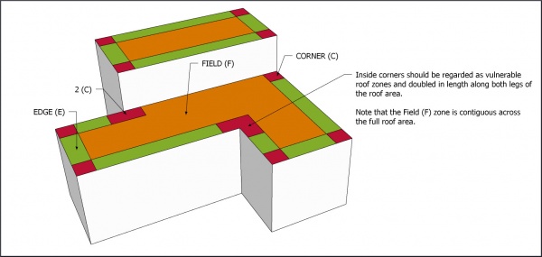
- When a roof area intersects the corner of a wall, the Edge zone on either side of the wall corner must be treated as a roof Corner (2 x C) (Figure 3.1.3.2.-B).
- When an existing roof system is specified for partial replacement, the Design Authority must
- calculate the Specified Wind Loads for the roof,
- determine if securement of the remaining roof components (left in situ) is sufficient to resist the Specified Wind Loads,
- determine a suitable method of securement or have the system of securement engineered, and
- calculate and design securement for any overburden, amenities, or equipment.
- Roof systems should be designed in conjunction with the electrical systems for the building, to avoid unnecessary interference with roof system securement (See also Subsection 2.1.8., "Electrical Cables and Boxes").
- Mansards are a roof system and are therefore subject to the requirements in this Part.
- Securement of an adjoining water-shedding system shall be made in accordance with the requirements in the applicable Standard.
- Wind loads for a roof assembly supporting a vegetated roof system shall be determined in accordance with the requirements of the Building Code and Article 3.1.3.3. of the “RGC Standard for Vegetated Roofs”.


3.1.3.3. Resistance to Specified Wind Loads
- The wind uplift resistance capabilities of the selected roof system must equal or exceed the Specified Wind Loads calculated for each roof zone to which the system will be applied (see Article 3.1.3.2.).
- Engineered designs to resist wind uplift may refer to the "British Columbia Building Code", Div. B, Appendix C, "Table C-2", which lists various types of loads, including wind loads, for specific reference locations throughout the province.
- Notwithstanding the foregoing, no roof shall be constructed on a non-veneered panel roof deck unless it conforms to the requirements in Article 2.1.5.6.
3.1.3.4. Resistance to Other Loads
- In addition to its capacity to resist Specified Wind Loads, the roof system must be capable of resisting or accommodating
- all anticipated live and dead loads, including (without limitation) other environmental loads, such as rain and snow, expected for the building’s size and location,
- gravity ("drag") loads,
- loads from overburden (See Part 14), and
- thermal expansion and contraction of the roof system components.
- Where the roof is designed to support a vegetated roof system, consideration for other loads shall conform to the requirements in Article 2.1.4.1. of the “RGC Standard for Vegetated Roofs”.
3.1.3.5. Submittals
- Refer to the requirements in Article 1.3.2.4.
3.1.4. Conventionally Insulated Roof Systems
(The requirements in Subsection 3.1.3., "All Systems", shall be read together with the following articles)
3.1.4.1. Securement Against Specified Wind Loads
(See Note A-3.1.4.1.)
- New and fully replaced conventionally insulated systems shall satisfy the requirements of the "British Columbia Building Code" and this Part, and shall be (when applicable)
- an Adhesive Applied Roof System ("AARS"),
- a Partially Attached Roof System ("PARS"), or
- a Mechanically Attached Roof System ("MARS"),
which may be specified as
- a Tested Assembly,
- an Assembly with Proven Past Performance, or
- an assembly with custom-engineered securement.
3.1.4.2. Specifying a Tested Assembly
(See Note A-3.1.4.2.)
- Only roof assemblies that have been tested by qualified facilities wholly independent of roof system manufacturers, using CSA-A123.21, "Standard test method for the dynamic wind uplift resistance of membrane-roofing systems" (latest edition), will be considered valid Tested Assemblies, for the purposes of this Standard (See here for a list of qualified testing agencies).
- The Design Authority is strongly encouraged to specify the application of a Tested Assembly, for any design of a new or fully replaced membrane waterproofing roof system.
- The Design Authority must use only the test observation readings that have been adjusted for the "Safety Factor" (CSA-A123.21, prior to the 2019 edition) or the "Resistance Factor" (CSA-A123.21, 2019 and newer), which must equal or exceed the highest Specified Wind Loads for the roof (this adjusted value is called the Dynamic Uplift Resistance, or DUR. See Figure 3.1.4.2.-A).
- When a Tested Assembly report indicates only one system of securement, that system shall be applied to all roof zones; alternatively, zone-specific securement requirements may be extrapolated by a Registered Professional "skilled in the work concerned", using ANSI-SPRI WD-1, "Wind Design Standard Practice for Roofing Assemblies" (see the "British Columbia Building Code", Division B, Part 5, Notes to Part 5, A-5.2.2.2.(4)).
Figure 3.1.4.2.-A Dynamic Uplift Resistance
Forming Part of Article 3.1.4.2.
(Click to expand illustration)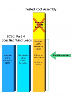
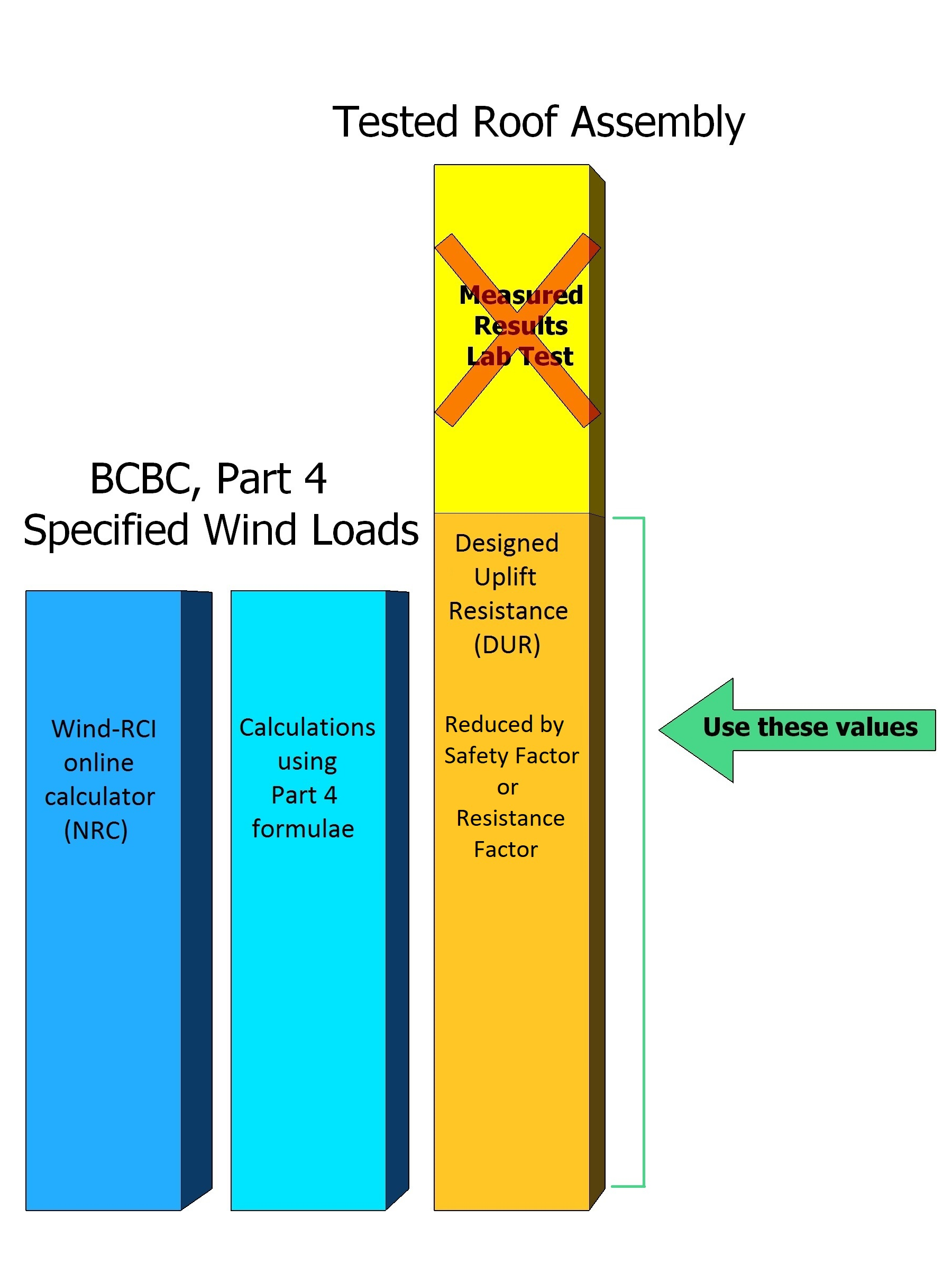
3.1.4.3. Specifying an Assembly with Proven Past Performance
(See the "British Columbia Building Code", Division B, Part 5, Notes to Part 5, A-5.1.4.1.(5) for an expanded explanation of the tests for "proven past performance")
- A new conventionally insulated roof assembly (the new roof assembly) may be designed using a model roof assembly as a reference (the roof Assembly with Proven Past Performance), but only when
- a Tested Assembly cannot be used,
- the material components identified in a Tested Assembly are not accepted by the RoofStar Guarantee Program, and the test report offers no RoofStar-accepted alternates,
- a Tested Assembly is not available because a material or system has not been tested, or because the Specified Wind Loads exceed the capacity of an available or suitable Tested Assembly,
- the model roof assembly
- is an existing roof assembly constructed on a real, existing building (the model building),
- demonstrates resistance to negative wind loads that are the same as, or greater than, the Specified Wind Loads which the new roof assembly must be designed to resist,
- has a history of performance equal to or longer than the expected service life of the new roof assembly, and
- is designed with only RoofStar-accepted materials that possess properties "identical or superior to those of the...assembly used as a reference" (Ref. the "British Columbia Building Code", Division B, Notes to Part 5, Environmental Separation),
- the model building
- is similar in dimensions, exposure, openings, and importance to the building that will support the new roof assembly, and
- is situated in conditions representative of the building that will support the new roof assembly (the term "representative" refers to conditions that include, without limitation, dynamic loads caused by proximity to other structures because of funneling or building harmonics).
- To qualify for a RoofStar Guarantee, a new roof assembly patterned after a model roof assembly and the design using a model roof assembly must be supported with a letter of assurance provided to the Guarantor by the Design Authority, or by the manufacturer of the Assembly with Proven Past Performance, signed by the Principal or a person having the authority of the Principal, stating that the new roof assembly will resist the Specified Wind Loads calculated for the new roof assembly.
- A new roof assembly patterned after a model roof assembly may be used for partial roof replacement.
- Published approvals issued by an insurer or underwriter, or roof assembly designs warranted or guaranteed by anyone other than the Guarantor, do not satisfy the requirements for a roof Assembly with Proven Past Performance.
3.1.4.4. Specifying a Custom-engineered Securement Design
- When, for various reasons, a system of securement cannot be designed using either a Tested Assembly or an Assembly with Proven Past Performance, the securement system must be designed by a Registered Professional "skilled in the work concerned" (See the "British Columbia Building Code", Division C, Part 2, Article 2.2.1.2., "Structural Design").
3.1.5. Uninsulated Systems
(The requirements in Subsection 3.1.3., "All Systems", shall be read together with the following articles)
3.1.5.1. Securement against Specified Wind Loads
- All uninsulated roof systems must be designed to resist displacement by Specified Wind Loads, using the options articulated in Article 3.1.4.1.
- Where air intrusion into the roof assembly could compromise its securement, every roof assembly design must provide guidance for the installation of control layers, particularly where control layers intersect roof drains, penetrations, or assemblies adjacent to the roof (i.e., walls) (Ref. Part 6, "Air and Vapour Controls").
- When the in-service roof on a wood-frame structure in both uninsulated and vented, the replacement roof system should be designed around the principles of Article 7.1.5.2., which may affect the securement of the new roof assembly .
3.1.6. Protected Roof Systems
(The requirements in Subsection 3.1.3., "All Systems", shall be read together with the following articles)
3.1.6.1. Securement of Ballasted Roof Systems
(See Note A-3.1.6.1.. Also see Subsection 9.1.6., "Protected Roof Systems")
- Roof systems secured with stone (gravel) ballast, pavers, or a combination of each, must be designed to resist displacement by Specified Wind Loads, regardless of any overburden the design may call for.
- The securement of all roof systems held in place by ballast must be designed by a registered professional "skilled in the work concerned" ("British Columbia Building Code", Division C, Section 2.2., "Administration"), and ballast rates shall conform to
- the minimum requirements in Table 3.1.6.1. (Ref. Article 3.3.5.1., "Ballasted Systems", and Subsection 9.3.6., "Protected Roof Systems"), or
- extrapolated values using ANSI-SPRI RP-4 (latest edition), "Wind Design Standard for Ballasted Single-ply Roofing Systems".
- Stone ballast size for all ballasted roof systems shall conform to ASTM D7655/D7655M-12, "Standard Classification for Size of Aggregate Used as Ballast for Membrane Roof Systems".
- To facilitate resistance to Specified Wind Loads,
- a filter fabric is required beneath gravel or paver ballast, and
- a protection layer is required beneath crushed ballast.
- On roofs specified to utilize stone ballast, no fewer than two parallel rows of pavers should be considered for Corner and Edge zones, to prevent or reduce wind scouring of the gravel.
- When pavers are selected as ballast for a roof system, the Design Authority must determine the support and placement of pavers to resist displacement by Specified Wind Loads.
- Vegetated roof systems designed as ballast for a protected membrane roof assembly shall be designed in accordance with the requirements in Part 3 of the “RGC Standard for Vegetated Roofs”.
Table 3.1.6.1.
Minimum Requirements for Stone Ballast
Forming Part of Article 3.1.6.1.
(Note: these requirements apply only where no other guidance for stone ballast
has been provied by the Design Authority)
XPS Insulation
ThicknessStone Ballast Required Weight Minimum Ballast Depth
(approximate)†Up to 50.8 mm (2") 60 Kg/M2 (12 lb./sf) 44.45 mm (1-3/4") 76.2 mm (3") 80 Kg/M2 (17 lb./sf) 57.15 mm (2-1/4") 101.6 mm (4") 108 Kg/M2 (22 lb./sf) 76.2 mm (3") 125 mm (5") 132 Kg/M2 (27 lb./sf) 88.9 mm (3-1/2") 152.4 mm (6") 156 Kg/M2 (32 lb./sf) 107.95 mm (4-1/4") 177.8 mm (7") 180 Kg/M2 (37 lb./sf) 125 mm (5") 203.2 mm (8") 204 Kg/M2 (42 lb./sf) 139.7 mm (5-1/2")
- † These minimum requirements should be noted by the registered professional
designing the ballast system.
- † These minimum requirements should be noted by the registered professional
3.1.6.2. Securement of Modified Protected Roof Systems
- Modified protected roof systems shall be secured according to the requirements for conventionally insulated roofs supporting overburden.
3.1.7. Roof Replacement and Alterations
3.1.7.1. Complete Roof System Replacement
- Complete roof system replacement projects must be designed to secure the new roof system against displacement by Specified Wind Loads.
3.1.7.2. Partial Roof System Replacement
- Partial roof replacements must be designed to secure the roof system against displacement by Specified Wind Loads, in keeping with the requirements in Article 3.1.3.2. (See also Article 3.3.6.2.).
- When specifying securement for a partial roof replacement, the securement system must be designed and specified by the Design Authority (See also Subsection 1.1.4., "Replacement and Alterations"); nevertheless, mechanical fastening, when practicable, is the recommended method for securing new materials to an existing roof system (See Note A-3.1.7.2.).
Section 3.2. Materials
3.2.1. Material Properties
3.2.1.1. Substituting Materials Used in a Tested Assembly
(See Note A-3.2.1.1.)
- When a manufacturer's Tested Assembly incorporates materials (and listed alternates) that are not part of the RoofStar Guarantee Program, the Design Authority must identify appropriate substitutions for those materials from the list of RoofStar-accepted Materials, and obtain
- written approval from the technical manager of the manufacturer stating that the substituting material will not reduce the capabilities of the Tested Assembly, or
- a letter of support issued by a registered professional qualified to perform the work in Part 4 of the Building Code (Ref. the "British Columbia Building Code", Division C, Part 2, Article 2.2.1.2., "Structural Design").
- Any material substitution should
- be limited to one (1) material component from the Tested Assembly, but the substitution of more than one material component is permissible provided the substitution complies with the other requirements in this Article, and
- be made in keeping with the decision process flows for MARS, PARS and AARS assemblies published in CSA-A123.21, "Standard test method for the dynamic wind uplift resistance of membrane-roofing systems" (latest edition), "Annex F".
- Because of its nature, a new roof assembly patterned after an Assembly with Proven Past Performance does not qualify for material substitution.
3.2.2. Securement Materials
3.2.2.1. Fasteners
- The minimum requirements in this Article apply to any roof system, regardless of requirements published elsewhere.
- The Design Authority should specify the correct type of fastener, keeping in mind
- pull-out strength, and
- corrosion resistance (contributing factors to fastener corrosion may include dissimilar metal contact, excessive building humidity, corrosive chemicals within components of the roof system, or corrosive elements provided within the building envelope etc.).
- Fasteners must be capable of securing the roof system components to resist Specified Wind Loads.
- Unless otherwise permitted in writing by the manufacturer, fasteners shall be resin-coated, self-drilling screws manufactured with recessed heads, and must be used in combination with plates, as shown in Table 3.2.2.1.
Table 3.2.2.1.
Minimum Fastener and Plate Requirements
Forming Part of Article 3.2.2.1.
(Note: these requirements apply only where no other guidance for fastener and plate types and sizes has been provided by the Design Authority)
| Material | Fastener Size |
Plate |
|---|---|---|
| Deck overlays | #12 | 73.03 mm (2-7/8”) Hexagonal, 76.2 mm (3”) Round or Square |
| Insulation | #12 | 73.03 mm (2-7/8”) Hexagonal, 76.2 mm (3”) Round or Square |
| Insulation Overlays | #12 | 73.03 mm (2-7/8”) Hexagonal, 76.2 mm (3”) Round or Square |
| Membranes | #14 | Proprietary |
3.2.2.2. Adhesives
- Adhesives used to secure any roof system materials must be acceptable to the manufacturer and be capable of resisting Specified Wind Loads.
- Adhesives listed in a selected Tested Assembly
- must be used to secure applicable layers within the roof system, and
- may be substituted only with products listed in the Tested Assembly report.
- In the absence of a Tested Assembly, or for adhered and partially adhered roof assemblies with Proven Past Performance, adhesives used to secure new roofing materials must be acceptable to the manufacturer and must be demonstrably capable of resisting Specified Wind Loads.
- Bitumen used as a hot-applied adhesive must be Type 3 or SEBS.
3.2.2.3. Stone (Gravel) Ballast
(See also Table 3.1.6.1. in Article 3.1.6.1.)
- Stone (gravel) ballast used to secure a roof system must be washed (clean) round or crushed stone and must conform to ASTM D7655/D7655M-12, "Standard Classification for Size of Aggregate Used as Ballast for Membrane Roof Systems", or to Table 3.2.2.3.
- The minimum requirements in this Article must not be reduced except by a written Variance that shall be endorsed in writing by the owner or the owner's representative, and submitted to the RoofStar Guarantee Program as part of the Guarantee record.
| Table 3.2.2.3. Stone Ballast Size and Grades Forming Part of Article 3.2.2.3. |
Nominal size Percentage Passing 38.1 mm (1-1/2") 100% 25.4 mm (1") 70 - 100% 19.05 mm (3/4") 5 - 20 % 12.7 mm (1/2") 0 - 6 % 4.76 mm (3/16") 0 - 2 %
3.2.2.4. Pavers and Pedestals
- Pavers that are partially supported (i.e., with pedestals) should be capable of resisting anticipated loads (i.e., hydraulically pressed concrete pavers).
- Pedestals
- should be adjustable when a level surface is required,
- must be purpose-made, and
- must include an integral spacer rib measuring at least a 3.18 mm (1/8”) in width, to uniformly separate pavers.
Section 3.3. Application
3.3.1. Guarantee Term Requirements
3.3.1.1. RoofStar 5-year Guarantee and RoofStar 10-year Guarantee
- To qualify for a RoofStar 5-year Guarantee or RoofStar 10-year Guarantee, all projects shall comply with the requirements in this Part.
3.3.1.2. RoofStar 15-Year Guarantee
- All projects intended to qualify for a RoofStar 15-year Guarantee shall comply with the requirements in this Standard for a RoofStar 5-year Guarantee or RoofStar 10-year Guarantee, and shall
- conform to the specified design when enhanced roof system securement is required (See Article 3.1.2.1.).
3.3.2. All Systems
3.3.2.1. Securing Systems with Mechanical Fasteners
- Unless otherwise specified by a Tested Assembly, a roof assembly with Proven Past Performance, or a custom-engineered assembly,
- fastener patterns shall conform to the minimum requirements published in Table 3.3.2.1.-B through Table 3.3.2.1.-G,
- the minimum number of fasteners must conform to the requirements in Table 3.3.2.1.-A, and
- fasteners shall be installed at least 152.4 mm (6”) from panel corners, measured from each edge of the panel, but the precise placement of fasteners shall be confirmed with the manufacturer.
- Fasteners used to secure boards from curling, or to secure boards at slope transitions, shall be additional to the minimum number of fasteners and plates required by a Tested Assembly, a roof assembly with Proven Past Performance, a custom-engineered assembly, or the patterns shown in Table 3.3.2.1.-B through Table 3.3.2.1.-G.
- When mechanically attached membranes are installed together with new insulation, the insulation assembly (with or without an insulation overlay) must be held in place independently from the membrane, with no fewer than four (4) fasteners per panel.
- Regardless of where fasteners are used in the roof system, when they penetrate and secure another material to a substrate, mechanical fasteners must conform to the requirements illustrated in Figure 3.3.2.1.-A and shall (unless exceeded by the fastener manufacturer’s published requirements)
- penetrate through the bottom surface of
- steel decks at least 19.05 mm (3/4") (fasteners should penetrate the top flutes only), and
- plywood sheathing by at least 19.05 mm (3/4").
- penetrate into solid dimensional lumber or concrete by at least 25.4 mm (1").
- penetrate through the bottom surface of
- Unless otherwise provided for in a Tested Assembly report, in the documentation for an Assembly with Proven Past Performance, or by a Registered Professional in a custom-engineered securement system, mechanical fastening of panel materials shall conform to the minimum RGC Guarantee historical requirements in Table 3.3.2.1.-A through Table 3.3.2.1.-G.
Figure 3.3.2.1.-A Fastener Penetration Into or Through Deck
Forming Part of Sentence 3.3.2.1.(4).
(Click to expand illustration)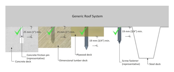

Table 3.3.2.1.-A.
Minimum Requirements for Mechanical Fastening
Forming Part of Article 3.3.2.1.
(Note: Fasteners may be located within 50.8 mm (2") (in any direction) of the positions shown in the diagrams,
but this must be validated by the manufacturer.)
Material Dimensions Roof Zone (Field, Perimeter, Corner) F P C 1219.2 mm x 2438.4 mm (48" x 96") Deck Overlay supporting mechanically attached materials 4 4 4 Insulation or Insulation Overlay supporting mechanically attached materials 4 4 4 Insulation 8 12 15 Insulation Overlays 8 12 15
1219.2 mm x 1828.8 mm (48" x 72") Insulation 6 8 12
1219.2 mm x 1219.2 mm (48" x 48") Insulation 5 6 8
914.4 mm x 1219.2 mm (36" x 48") Insulation 4 6 7
609.6 mm x 2438.4 mm (24" x 96") Insulation 5 6 8
609.6 mm x 1219.2 mm (24" x 48") Insulation 4 4 5
3.3.2.2. Securing Systems with Adhesives
- Adhesives may be used to secure new roofing materials to an existing roof system, provided the specific application procedures and methods are engineered by or for the Design Authority.
- Notwithstanding Sentence (1), the use of adhesive to secure insulation shall conform to Article 7.3.3.1.
3.3.2.3. Securing Roofs with Overburden
- Any overburden, including vegetated roof systems, must be installed in keeping with the designed securement methods and systems specified by the Design Authority, and shall also conform to the the requirements in Part 14 .
NOTE: Table 3.3.2.1.-B through Table 3.3.2.1.-G illustrate fastener patterns and placement based on historical Guarantee requirements, to provide optimum wind uplift resistance. These patterns are to be used only when patterns are not provided in a Tested Assembly, a roof assembly with Proven Past Performance, or in a custom-engineered assembly. Fasteners may be located within 50.8 mm (2") of position shown in diagrams in any direction, but this must be validated by the manufacturer.
Table 3.3.2.1.-B.
Minimum Mechanical Fastening Patterns for
Panels 1219.2 mm x 2438 mm (48" x 96")
Forming Part of Article 3.3.2.1.
(Click on drawing to expand)
1219.2 mm x 2438.4 mm (48" x 96") Field Perimeter Corner 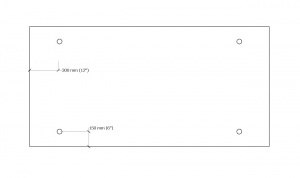 4 Fasteners 4 Fasteners 4 Fasteners
Field Perimeter Corner 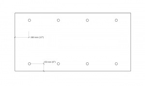 8 Fasteners
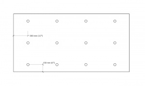 12 Fasteners
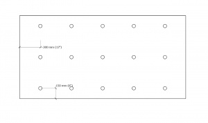 15 Fasteners


Table 3.3.2.1.-C.
Minimum Mechanical Fastening Patterns for
Panels 1219.2 mm x 1828.8 mm (48" x 72")
Forming Part of Article 3.3.2.1.
(Click on drawing to expand)
1219.2 mm x 1828.8 mm (48" x 72") Field Perimeter Corner 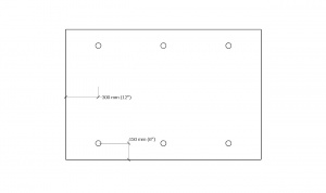 6 Fasteners
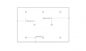 8 Fasteners
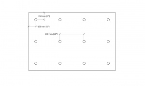 12 Fasteners
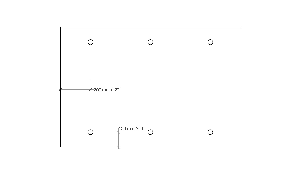


Table 3.3.2.1.-D.
Minimum Mechanical Fastening Patterns for
Panels 1219.2 mm x 1219.2 mm (48" x 48")
Forming Part of Article 3.3.2.1.
(Click on drawing to expand)
1219.2 mm x 1219.2 mm (48" x 48") Field Perimeter Corner 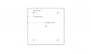 5 Fasteners
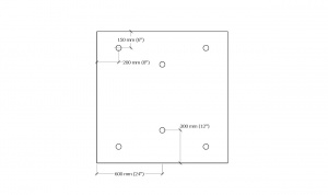 6 Fasteners
 8 Fasteners
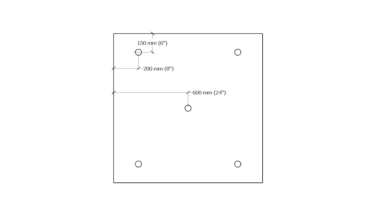
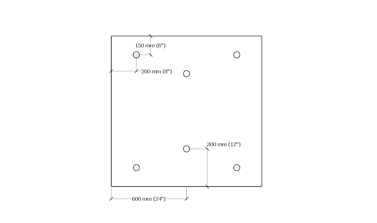
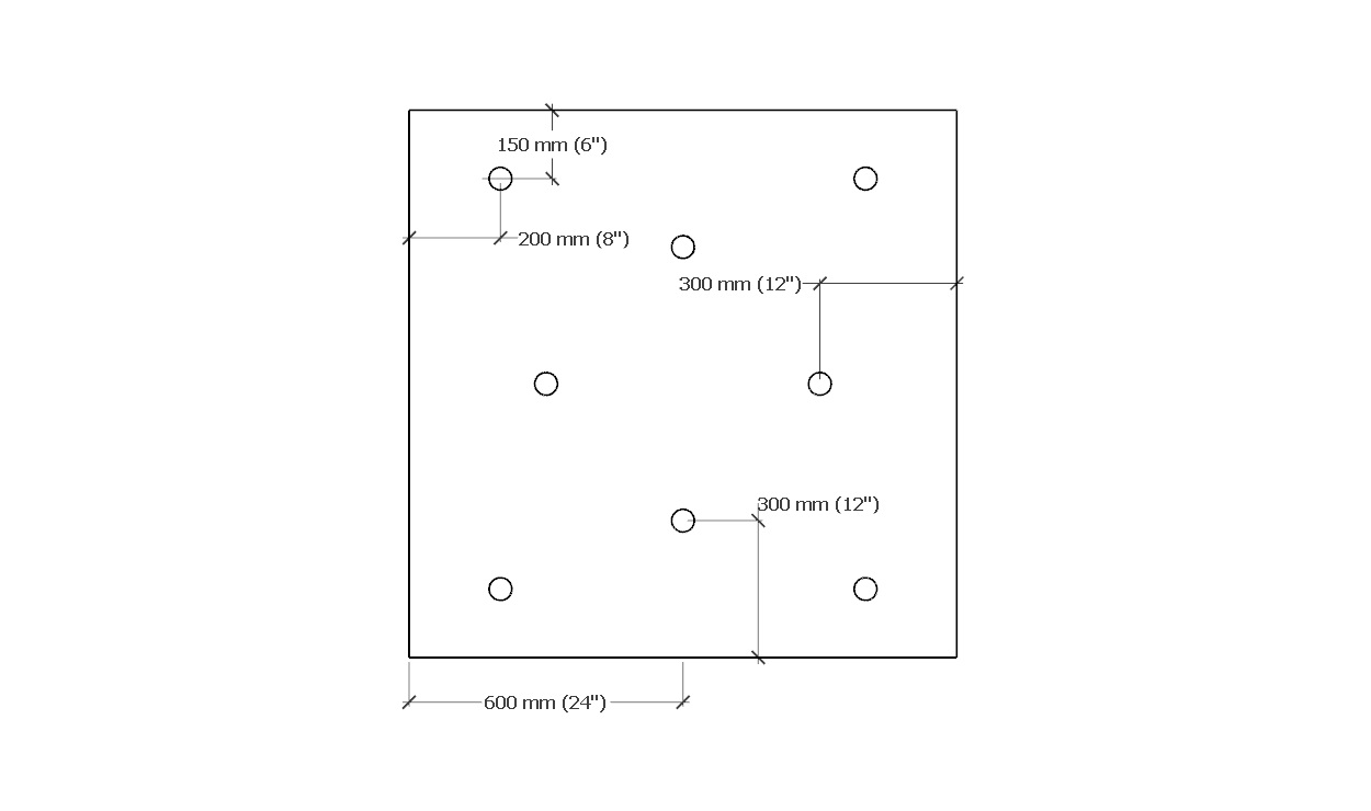
Table 3.3.2.1.-E.
Minimum Mechanical Fastening Patterns for
Panels 914.4 mm x 1219.2 mm (36" x 48")
Forming Part of Article 3.3.2.1.
(Click on drawing to expand)
914.4 mm x 1219.2 mm (36" x 48") Field Perimeter Corner  4 Fasteners
 6 Fasteners
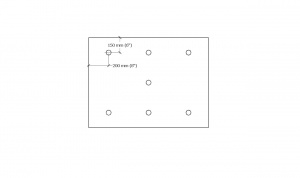 7 Fasteners
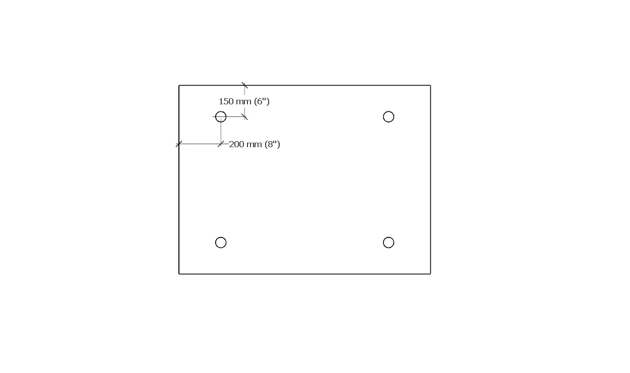
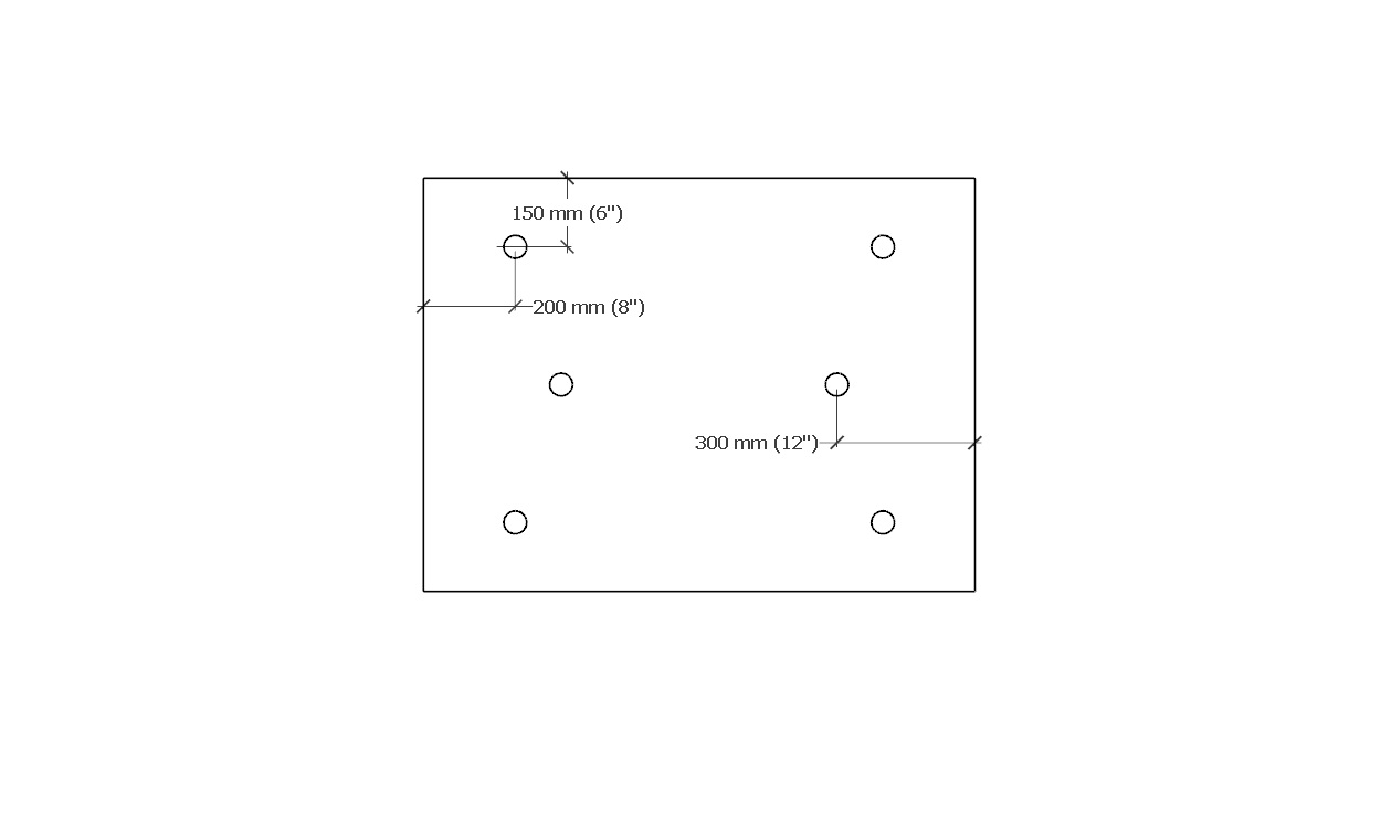

Table 3.3.2.1.-F.
Minimum Mechanical Fastening Patterns for
Panels 609.6 mm x 2438.4 mm (24" x 96")
Forming Part of Article 3.3.2.1.
(Click on drawing to expand)
609.6 mm x 2438.4 mm (24" x 96") Field Perimeter Corner 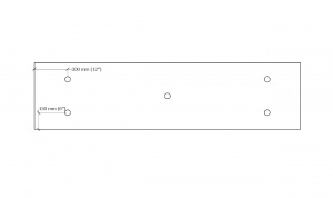 5 Fasteners
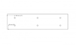 6 Fasteners
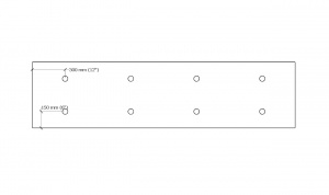 8 Fasteners

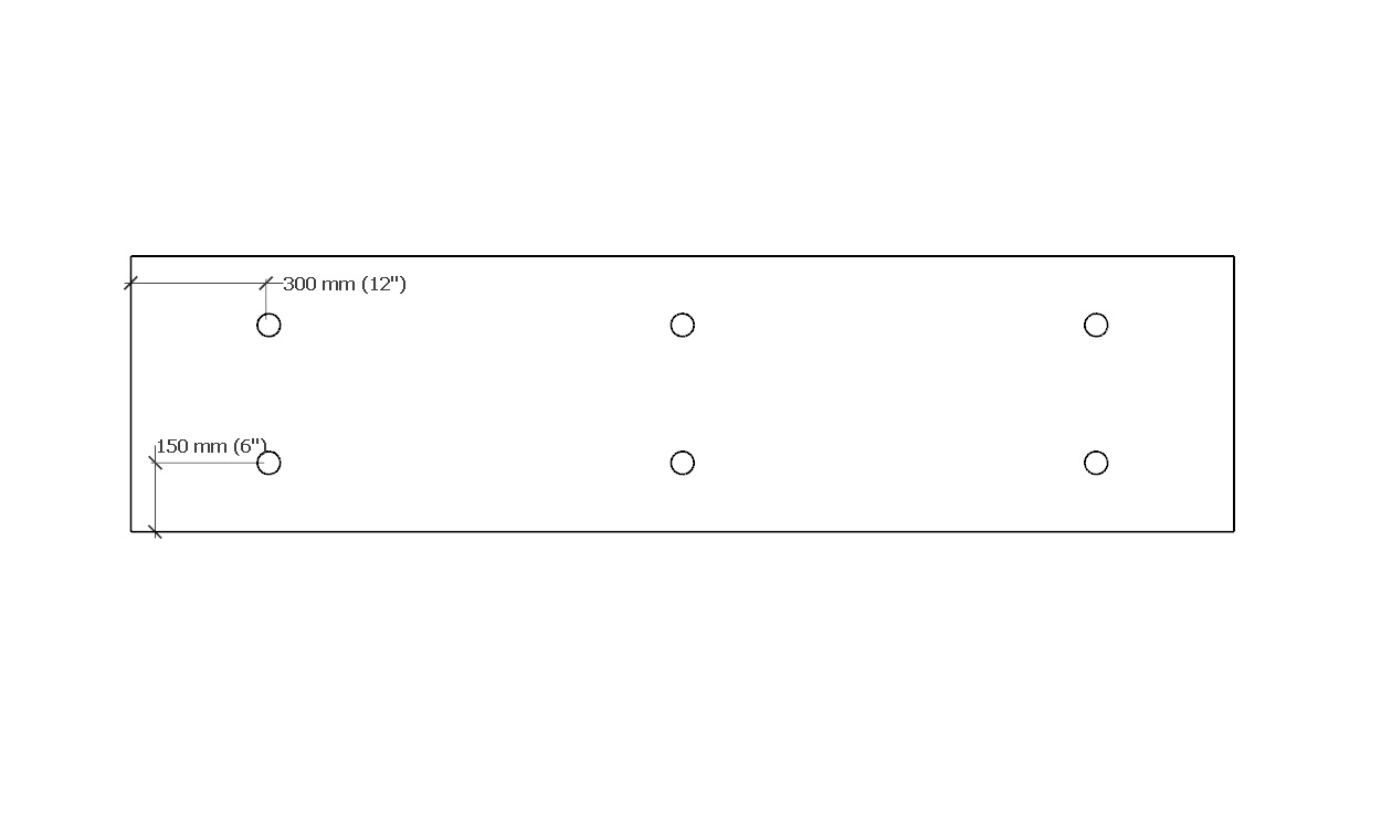

Table 3.3.2.1.-G.
Minimum Mechanical Fastening Patterns for
Panels 609.6 mm x 1219.2 mm (24" x 48")
Forming Part of Article 3.3.2.1.
(Click on drawing to expand)
609.6 mm x 1219.2 mm (24" x 48") Field Perimeter Corner 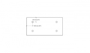 4 Fasteners 4 Fasteners
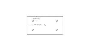 5 Fasteners

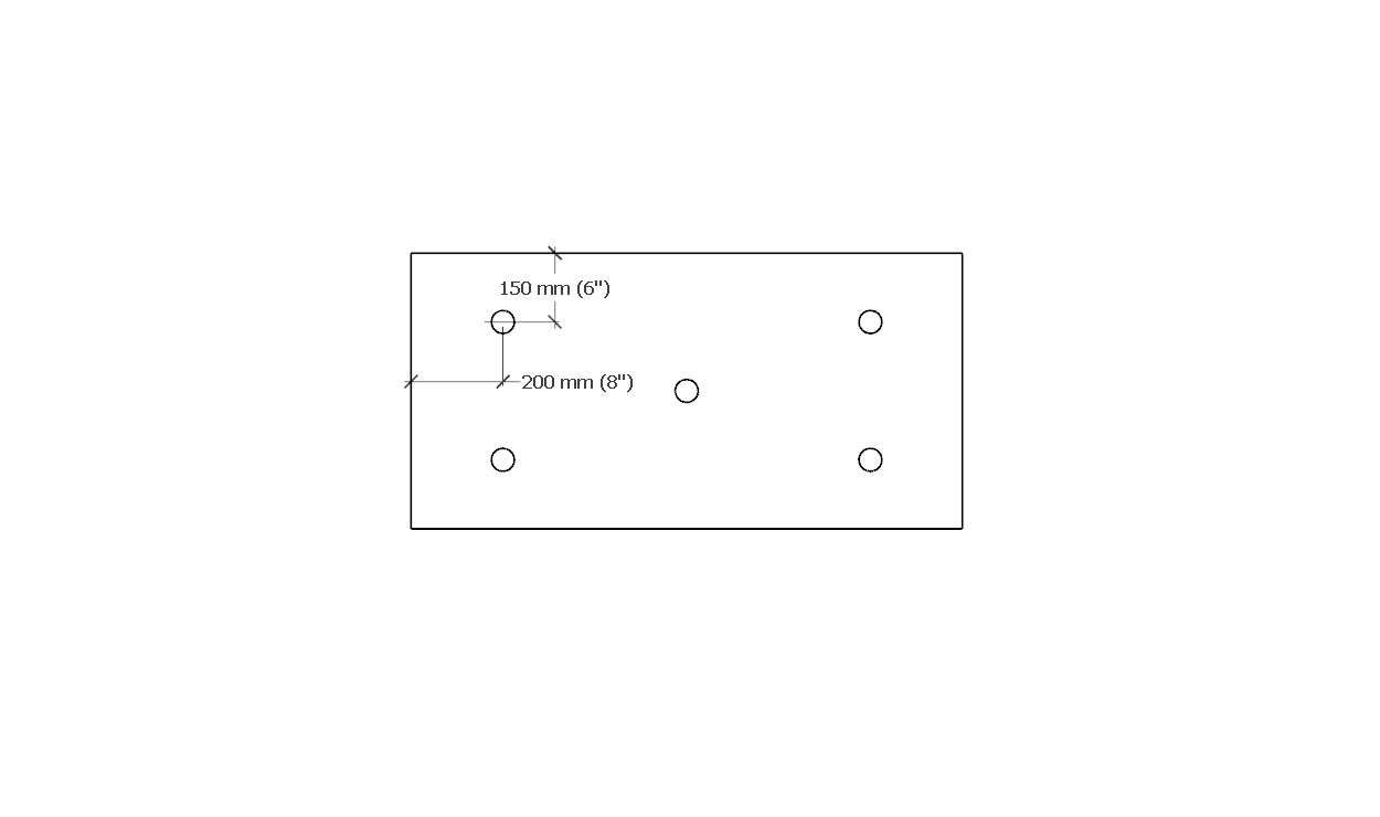
3.3.3. Conventionally Insulated Roof Systems
(The requirements in Subsection 3.3.2., "All Systems", shall be read together with the following articles)
3.3.3.1. General Requirements
- New and fully replaced conventionally insulated systems must be secured to conform to the Building Code, and shall be capable of resisting displacement by Specified Wind Loads using
- a Tested Assembly,
- an Assembly with Proven Past Performance, or
- an assembly with custom-engineered securement.
3.3.4. Uninsulated Systems
(The requirements in Subsection 3.3.2., "All Systems", shall be read together with the following articles)
3.3.4.1. General Requirements
- All uninsulated roof systems that are not secured with ballast shall conform to the requirements in Article 3.1.4.1. for conventionally insulated systems.
- Uninsulated roof systems secured with stone ballast, pavers or both must be installed following the requirements in Article 3.3.5.1.
3.3.5. Protected Roof Systems
(The requirements in Subsection 3.3.2., "All Systems", shall be read together with the following articles)
3.3.5.1. Ballasted Systems
(Note: the reader must consult the Design and Application requirements for protected roof systems in Part 9).
- Roof systems secured with stone ballast, pavers, or both must be constructed to resist displacement by Specified Wind Loads.
- To facilitate resistance to Specified Wind Loads,
- a filter fabric is required beneath stone or paver ballast,
- a protection layer is required beneath crushed ballast, and
- stone ballast must conform to the specified design.
- Stone ballast shall
- be washed (clean) round or crushed material, and
- be selected (according to the specified design) to resist flotation and Specified Wind Loads.
- Pavers and unit-type masonry, such as brick or paving stones, must be supported by
- purpose-made pedestals conforming to the requirements in Article 3.2.2.4.,
- a proprietary drainage layer overlaid with a filter fabric mat, or
- a drainage layer of loose aggregate (such as pea gravel) measuring at least 25.4 mm (1”) in depth, installed over a filter fabric.
- Pedestals
- must permit at least 12.7 mm (1/2″) of vertical separation between the paver and the underlying substrate, to provide airflow for drying surfaces and assist in leveling,
- should not impede the flow of water or air, and
- should uniformly distribute the dead load of pavers, and other unit masonry products, as well as predicted live loads.
- Pavers must be tied together when specified by the design.
- When a vegetated roof system is used as ballast, the installation shall conform to Part 10 of the “RGC Standard for Vegetated Roofs” (See also Part 3 in the same Standard, concerning design requirements).
3.3.6. Roof Replacement and Alterations
3.3.6.1. Complete Roof System Replacement
- Roof systems that are removed and replaced in their entirety (excluding the air or vapour controls, which may be left in place at the discretion of the Design Authority) must be secured following the requirements for new roof systems.
3.3.6.2. Partial Roof Replacement
- When only a portion of an existing roof system is specified for replacement, the new materials must be secured to resist Specified Wind Loads (See also Subsection 1.1.4., "Replacement and Alterations").
- Mechanical fastening is the most reliable method for securing new materials installed over an existing roof assembly, but when mechanical fastening is not practicable, the system of securement must be
- custom-engineered, or
- patterned after a roof assembly with Proven Past Performance, in keeping with the requirements in Article 3.1.4.3.
Part 4 - Materials
Section 4.1. Design
4.1.1. General
4.1.1.1. Scope
- The scope of this Part and the Standard shall be as described in Division A, Part 1.
4.1.1.2. Defined Terms
- Words that appear in italics are defined in the Glossary. Additionally, the following terms are used in this Part:
- Primary Material means a material used in a roof or grade-level waterproofing system that protects a building interior from water. Primary materials are often exposed to the weather (protected membranes are an exception), and therefore also protect secondary materials from damage. Membranes, metal panels, asphalt shingles, and cedar shakes and shingles, form the core body of materials classified as primary.
- Secondary Material means one which forms part of a waterproofing system or water-shedding system, and which may affect the wind resistance characteristics of the entire assembly but is not necessarily exposed to the weather.
Section 4.2. Materials
4.2.1. Material Properties
4.2.1.1. Use of Accepted Materials
(For limitations and exclusions pertaining to materials, see Division A, Article 3.2.1.2.)
- All materials installed by the Contractor, for new construction or alterations, must be
- newly manufactured (except for reusable insulation; see Article 7.1.3.2.), and may not be recycled without the expressed, written consent of the Guarantor,
- accepted by the RoofStar Guarantee Program, and
- manufactured by, or listed as acceptable to, the manufacturer of the primary material.
- All uninstalled materials must be
- protected from weather with wrappers approved or recommended by the manufacturer,
- properly stacked, and
- secured above ground or on the roof surface.
- All installed roofing materials that are susceptible to moisture damage must be made watertight by the end of each workday.
- Metals and fasteners must be compatible with each other, to avoid galvanic corrosion which can occur when dissimilar metals contact each other.
Section 4.3. Application
4.3.1. Guarantee Term Requirements
4.3.1.1. RoofStar 5-year Guarantee and RoofStar 10-year Guarantee
- To qualify for a RoofStar 5-year Guarantee or RoofStar 10-year Guarantee, all projects shall comply with the requirements in this Part.
4.3.1.2. RoofStar 15-Year Guarantee
- To qualify for a RoofStar 15-year Guarantee, all projects shall comply with the requirements in this Part for a RoofStar 5-year Guarantee or RoofStar 10-year Guarantee.
4.3.2. All Systems
4.3.2.1. Application of New Materials
- All new materials installed as part of the roof system shall conform to the manufacturer's published requirements, unless superseded by this Standard.
Part 5 - Deck and Wall Overlays
(See Note A-5)
Section 5.1. Design
5.1.1. General
5.1.1.1. Scope
- The scope of this Part and the Standard shall be as described in Division A, Part 1.
5.1.1.2. Defined Terms
- Words that appear in italics are defined in the Glossary.
5.1.2. Guarantee Term Requirements
5.1.2.1. RoofStar 5-year Guarantee and RoofStar 10-year Guarantee
- To qualify for a RoofStar 5-year Guarantee or RoofStar 10-year Guarantee, all projects shall comply with the requirements in this Part.
5.1.2.2. RoofStar 15-Year Guarantee
- To qualify for a RoofStar 15-year Guarantee, all projects shall comply with the requirements in this Part for a RoofStar 5-year Guarantee or RoofStar 10-year Guarantee.
5.1.3. All Systems
5.1.3.1. Required Use of Overlays
(See Note A-5.1.3.1.; see also Part 9 and Part 10 for substrate preparation requirements)
- A deck or wall overlay must be specified when
- a thermal layer is required by the Building Code,
- it is required as part of a Tested Assembly, or
- the conditions of the deck or wall are unsuitable for receiving roofing materials.
- When a roof design includes any type of overburden, the deck overlay on steel decks, or on wood decks less than 25.4 mm (1”) thick, should be at least 15.88 mm (5/8”) thick, to stiffen the supporting surface and reduce deck deflection.
Section 5.2. Materials
(See Division C, "Accepted Materials")
5.2.1. Material Properties
5.2.1.1. Suitability of Overlays
- Deck and wall overlays must be
- listed in Division C,
- acceptable to the manufacturer,
- suitable for the type of deck, and
- suitable for, and compatible with, any membrane or panel application.
- When plywood is used as a deck overlay, only tongue-and-groove plywood is acceptable and must be
- at least 12.7 mm (1/2”) thick when installed over a mass timber deck, or
- at least 15.88 mm (5/8”) thick, when the roof supports overburden.
5.2.1.2. Thermal Barrier
- When the Code having jurisdiction requires a thermal barrier, any material selected from Division C must be suitable for the purpose.
5.2.1.3. Overlays for Walls
- In addition to overlays listed in Division C, walls may be overlaid with
- plywood, provided the plywood is least 12.7 mm (1/2”) thick and is pressure-treated when applied over concrete or concrete masonry units (CMU), or
- fibre-mat reinforced cement boards with a minimum thickness of 9.53 mm (3/8"), conforming to ASTM C1325 (latest edition), "Standard Specification for Fiber-Mat Reinforced Cementitious Backer Units".
5.2.1.4. Fasteners
- Refer to Article 3.2.2.1.
Section 5.3. Application
(This Section shall be read in conjunction with the requirements for substrate preparation in Part 9 and Part 10)
5.3.1. Guarantee Term Requirements
5.3.1.1. RoofStar 5-year Guarantee and RoofStar 10-year Guarantee
- To qualify for a RoofStar 5-year Guarantee or RoofStar 10-year Guarantee, all projects shall comply with the requirements in this Part.
5.3.1.2. RoofStar 15-Year Guarantee
- To qualify for a RoofStar 15-year Guarantee, all projects shall comply with the requirements in this Part for a RoofStar 5-year Guarantee or RoofStar 10-year Guarantee.
5.3.2. All Systems
5.3.2.1. Support, Arrangement, and Securement of Deck Overlays
- Deck overlays must be
- fully or intermittently supported along all edges by the deck, and
- installed in a staggered pattern (offset) 304.8 mm (12") from adjacent board rows (a minus offset tolerance of 50.8 mm (2") maximum will be permitted to compensate for variance in the manufacturer's tolerance of differing board widths and lengths).
- Deck overlays shall be affixed to the deck with
- mechanical fasteners conforming to the requirements in Article 3.2.2.1.,
- polyurethane foam adhesives acceptable to the manufacturer and conforming to the requirements in Article 3.2.2.2., or
- a combination of mechanical fasteners and polyurethane foam adhesives.
- When mechanical fasteners are used to secure deck overlays, the minimum number of fasteners (in combination with plates) shall be
- four (4), for every 1219.2 mm x 2438.4 mm (48" x 96") sheet, or
- as specified by a Tested Assembly, when part of a "PARS" or "MARS" conventionally insulated system.
5.3.2.2. Overlays on Steel Decks
- RoofStar-accepted deck overlay boards used as a thermal barrier to achieve a specific fire rating must conform to the applicable code and insurance requirements for the roof system.
- When the roof system is uninsulated, the deck must be overlaid with at least one 12.7 mm (1/2”) thick layer of
- moisture resistant gypsum core deck overlay board,
- a membrane-laminated overlay panel accepted by the Guarantor for this application, or
- plywood.
5.3.2.3. Overlays on Concrete Decks
- A deck overlay board is not mandatory on a concrete supporting deck, but when it is specified, it must be installed to conform to the requirements in this Part.
5.3.2.4. Overlays on Wood Decks
- A mechanically fastened overlay board is required for any deck structure that does not meet the deck fastening criteria set out in Article 2.1.5.3.
5.3.2.5. Support, Arrangement, and Securement of Wall Overlays
- Wall overlay panels must be
- mechanically fastened with screw fasteners spaced no more than 304.8 mm (12”) O.C., both vertically and horizontally; fasteners must align with structural supports, and shall be placed
- at the perimeters,
- at the corners, and
- in the field, or
- adhered with a polyurethane adhesive, applied with a continuous z-patterned ribbon spaced no less than 304.8 mm (12”) apart.
- mechanically fastened with screw fasteners spaced no more than 304.8 mm (12”) O.C., both vertically and horizontally; fasteners must align with structural supports, and shall be placed
Part 6 - Air and Vapour Controls
(See Note A-6)
Section 6.1. Design
6.1.1 General
6.1.1.1. Scope
(See Note A-6.1.1.1.)
- The scope of this Part and the Standard shall be as described in Division A, Part 1.
6.1.1.2. Defined Terms
- Words that appear in italics are defined in the Glossary. Additionally, the following terms are used in this Part:
- Air barrier means a material that is manufactured and tested to prohibit the passage of air through that material.
- Continuity means a sealed, resistive, continuous connection
- between control layers that have the same function, and
- between a control layer and another material or object it joins to (i.e., a roof drain or penetration).
- Control layer means a material used in a roof assembly or wall assembly, that is manufactured and tested to resist or control the movement of air, vapour, or liquid water into or through that assembly.
- Vapour retarder means a material that is manufactured and tested to prohibit or regulate the passage of water vapour through that material.
- Water resistive barrier (WRB) means a material that is manufactured and tested to resist the transmission of liquid water through the material, and is usually used in wall assemblies.
6.1.2. Guarantee Term Requirements
6.1.2.1. RoofStar 5-year Guarantee and RoofStar 10-year Guarantee
- To qualify for a RoofStar 5-year Guarantee or RoofStar 10-year Guarantee, all projects shall comply with the requirements in this Part.
6.1.2.2. RoofStar 15-Year Guarantee
- To qualify for a RoofStar 15-year Guarantee, all projects shall comply with the requirements in this Part for a RoofStar 5-year Guarantee or RoofStar 10-year Guarantee.
6.1.3. All Systems
6.1.3.1. Responsibility for Design
- The Design Authority is responsible to specify
- air and vapour control materials,
- the placement of continuous air and vapour control layers in relation to a roof system and its components, and
- the selection of suitable materials for that application (See Note A-6.1.3.1.).
- The Design Authority is urged to review and consider the performance characteristics of materials available for such applications.
- Coverage under the RoofStar Guarantee shall be as described in Division A, Article 3.2.1.2..
- Notwithstanding coverage provisions in Division A, neither the RoofStar Guarantee Program nor the Contractor will accept any responsibility for damage to, or failure of, the roof system caused by the use or absence of air or vapour control layers.
6.1.3.2. Continuity of Control Layers
- The Design Authority, and trades constructing walls and roofs, are jointly responsible for making proper connections (continuity) between air and vapour control systems, including the transitions between wall systems and roof systems.
- Where air, vapour, or water control layers intersect a roof drain, overflow drain, scupper drain, or penetration, the intersection must be designed for continuity, and drawings must detail the execution of continuity for the Contractor.
- Overflow drains and scupper drains that penetrate wall assemblies must be designed and drawn to prevent air intrusion from the outside environment (Ref. Article 3.1.5.1.).
6.1.3.3. Use of Air Control Materials
- The Design Authority is responsible for the selection of air control materials (some air control layers are considered vapour permeable, others vapour-impermeable); roof systems intended to qualify for a RoofStar Guarantee should be designed according to the regulatory design and installation requirements for effective, continuous air control systems.
- All materials selected by the Design Authority should conform to the material and performance characteristics required in the "British Columbia Building Code", Division B, Article 5.4.1.2., "Air Barrier System Properties".
6.1.3.4. Use of Vapour Control Materials
- Because continuous vapour control layers may be needed to limit “water vapour transmission and condensation, burn protection, and severe climatic conditions” (National Energy Code of Canada for Buildings 2020, Article 5.2.5.3.(1), "Other Considerations"; see also the "British Columbia Building Code", Division B, Article 5.5.1.1., "Required Resistance to Vapour Diffusion"), they are considered discretionary and must be specified by the Design Authority.
- Where continuous vapour control layers are required and specified by Code, the RoofStar Guarantee Program requires that a suitable vapour control system be selected by the Design Authority and properly installed by the Contractor in conformity with the vapour control layer manufacturer’s published instructions, and with the Design Authority’s specified details.
6.1.3.5. High-humidity Building Interiors
- Careful consideration should be given to the performance characteristics of air and vapour control layers when specifying such a membrane for roof systems constructed over high-humidity building interiors, which may be susceptible to the accumulation of moisture within the roof system unless effective air and vapour controls are installed; these building interiors include (but are not limited to)
- swimming pools,
- commercial laundry facilities,
- large aquariums, and
- paper mills.
6.1.3.6. Membrane Roofs Installed on Vented Wood-Frame Structures
- Because some uninsulated, vented wood-frame roofs may be subjected to moisture intrusion from below (the consequence of a compromised air/vapour control layer, or its complete absence), refer to Article 7.1.5.2. for design ‘best practices’ .
Section 6.2. Materials
6.2.1. Material Properties
6.2.1.1. Compatibility with Other Materials
- The material selected for air and vapour control layers must be compatible with any other materials in the roof or wall assembly to which the control layer may come in contact, including (without limitation) contact with primers and adhesives, substrates, solvents, and cleaners.
6.2.1.2. Permitted Materials for RoofStar Guarantee
(See Note A-6.2.1.2.)
- While responsibility for the selection of suitable air and vapour control layers rests with the Design Authority, a roof designed and built to qualify for a RoofStar Guarantee shall not include
- polyethylene sheet plastic, or
- bitumen-impregnated kraft paper.
6.2.1.3. Puncture Resistance and Thickness
- Air and vapour controls should be installed over a continuous smooth plane, regardless of a material's ability to span voids or spaces in the deck.
- Fully supported air and vapour control layers should possess a minimum published static puncture resistance rating of 150 N (34 lbf) (Ref. CGSB-37.56-M for both test method and standard limits) and be either self-adhering or torch-applied; a high puncture resistance is necessary for the membrane to withstand accidental damage during construction.
- Where no deck overlay board is installed and the air and vapour control layers are partially unsupported (for example, on a steel deck), the control layers must possess a published static puncture resistance of at least 400 N (90 lbf).
- Should the air or vapour control layers be used as a temporary roof during project construction by either the Contractor or by other trades, a minimum 2 mm thick bituminous membrane is recommended.
6.2.1.4. Self-adhered and Torch-applied Materials
- Self-adhering or adhesive-applied materials should be considered as alternatives to torch-applied membranes when the substrate to which they will be applied is combustible, or when nearby structures, openings or materials present a fire hazard.
- A suitable separation or overlay material may be used as protection from open flame is acceptable; the application of materials to a combustible surface, using a torch, is strictly prohibited.
6.2.1.5. Vapour Controls for Concrete Decks
- Because curing concrete releases considerable moisture that can compromise the performance of a roof system, a vapour control layer installed on new concrete decks (28 days or older) must be selected to prevent condensation inside the roof system.
- A membrane with a permeability of 0.01 perms (Class I) is recommended for applications on concrete substrates, but the selection of vapour control materials is nevertheless the responsibility of the Design Authority.
Section 6.3. Application
6.3.1. Guarantee Term Requirements
6.3.1.1. RoofStar 5-year Guarantee and RoofStar 10-year Guarantee
- To qualify for a RoofStar 5-year Guarantee or RoofStar 10-year Guarantee, all projects shall comply with the requirements in this Part.
6.3.1.2. RoofStar 15-Year Guarantee
- To qualify for a RoofStar 15-year Guarantee, all projects shall comply with the requirements in this Part for a RoofStar 5-year Guarantee or RoofStar 10-year Guarantee.
6.3.2. All Systems
6.3.2.1. Continuity and Support
- The Contractor must
- ensure that air and vapour control layers in the roof system field, and at perimeters, are installed to provide at least 101.6 mm (4”) of overlap, for continuity of matching layers in adjacent assemblies,
- ensure that air and vapour control layers are sealed to penetrations and drains that pass through or enter the roof assembly, and
- seal all control layers to matching layers in adjacent assemblies (i.e., walls), when a roof is replaced.
- Installation of all air and vapour control materials must be smooth and uniform, without wrinkles or fish-mouths, and must also conform to the manufacturer’s published requirements and the Design Authority’s design details.
- All air and vapour control membrane side and end laps must be fully supported, in the field and at transitions with curbs, parapets, walls, and penetrations.
- When self-adhered membranes are applied directly to a steel supporting deck,
- membranes should be oriented parallel to the direction of deck flutes, and
- membrane laps and changes in plane must be supported by deck flutes, or by flat metal supports secured to the deck to span gaps.
- When metal supports are used to span gaps between steel deck flutes, they must be
- fabricated from pre-finished steel with a thickness no less than 24-gauge, and
- secured to the deck with no fewer than two (2) compatible screw fasteners per flute (See Figure 6.3.2.1.-A and Figure 6.3.2.1.-B).
- Roof drains, overflow drains, scupper drains, and penetrations must be detailed where they intersect an air, vapour, or water control layer, to provide continuity.
| Figure 6.3.2.1.-A Air, Vapour Controls Over Steel Deck With Metal Support Forming Part of Sentence 6.3.2.1.(5) (Click to expand illustration) |
Figure 6.3.2.1.-B Air, Vapour Controls Over Steel Deck With Deck Overlay Panel Forming Part of Sentence 6.3.2.1.(5) (Click to expand illustration) |
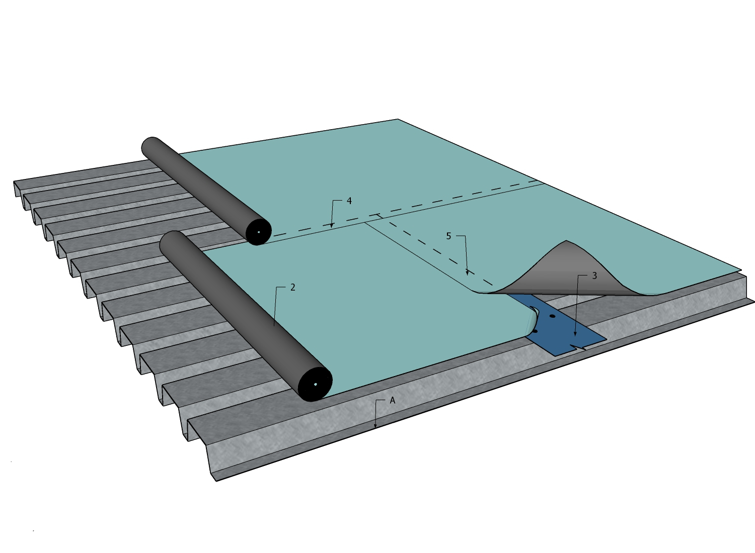 |
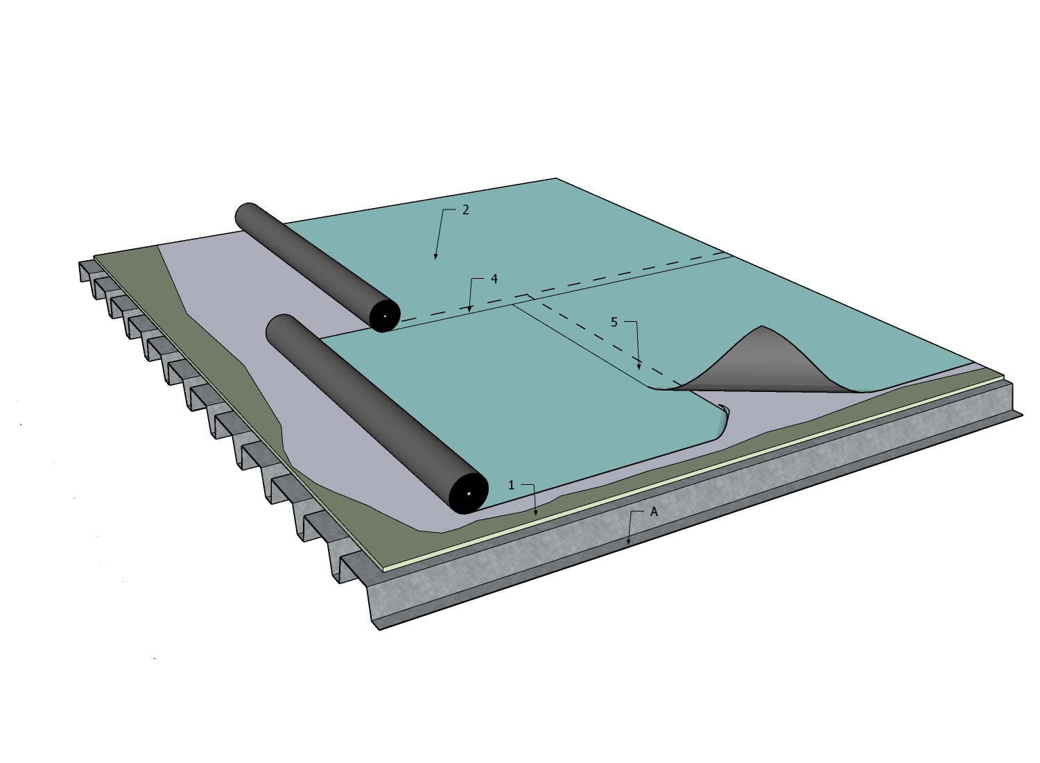
|
6.3.2.2. Torch-applied Materials
- The application of materials to an unprotected combustible material, using a torch, is strictly prohibited.
- All combustible materials MUST be protected from open flame by an acceptable separation or overlay material; this includes, without limitation, combustible materials
- on decks, walls, blocking, and canted edges, and
- that are hidden or obscured within voids, cracks, or orifices.
- When a torch-applied membrane is specified over combustible materials, all joints between overlay panels, and at roof-wall transitions, must be sealed with the primary membrane manufacturer’s approved self-adhered membrane or tapes.
- Where torch-applied membranes are not permitted or desirable, the installation of bituminous air and vapour control layers should align with the approaches described and required in Subsection 10.3.8., "Alternative Approaches to Sheet Membrane Flashing".
6.3.2.3. Securement on Slopes
- Self-adhered membranes applied to slopes greater than 1:6 (2” in 12”) should be additionally secured with mechanical fasteners in locations where slippage may occur, to counter-act material displacement resulting from temperatures that exceed the membrane’s service temperature.
6.3.2.4. Reserved
Part 7 - Insulation
Section 7.1. Design
7.1.1. General
7.1.1.1. Scope
- The scope of this Part and the Standard shall be as described in Division A, Part 1.
7.1.1.2. Defined Terms
- Words that appear in italics are defined in the Glossary. Additionally, the following terms are used in this Part:
- Heat-resistant insulation means insulation that resists heat and will not physically or chemically change when exposed to heat greater than 70°C (158°F), including heat from liquefied bitumen. Insulation boards of this type include fibreboard, polyisocyanurate, and mineral fibre ("wool"). Note that "heat-resistant" does not mean or even infer 'fire-proof'. While some heat-resistant insulation materials will resist burning for a time, only mineral fibre insulation will not burn.
- Heat-sensitive insulation means insulation that may be physically or chemically altered when exposed to heat greater than 70°C (158°F) — for example, heat from a torch or from liquefied bitumen. Heat-sensitive insulation includes EPS, XPS and polyurethane.
7.1.2. Guarantee Term Requirements
7.1.2.1. RoofStar 5-year Guarantee and RoofStar 10-year Guarantee
- To qualify for a RoofStar 5-year Guarantee or RoofStar 10-year Guarantee, all projects shall comply with the requirements in this Part.
7.1.2.2. RoofStar 15-Year Guarantee
- To qualify for a RoofStar 15-year Guarantee, all projects shall comply with the requirements in this Part for a RoofStar 5-year Guarantee or RoofStar 10-year Guarantee, and shall
- incorporate crickets at curbs and sleepers that impede drainage or are wider or longer than 1219.2 mm (48”), to provide positive slope to drains.
7.1.2.3. RoofStar Vegetated Roof Guarantee
- To qualify for a RoofStar Vegetated Roof Guarantee, the supporting roof assembly shall
- comply with the requirements in this Part for a RoofStar 5-year Guarantee, RoofStar 10-year Guarantee, or a RoofStar 15-year Guarantee,
- be acceptable to the manufacturer as support for a vegetated roof system, and
- comply with the related requirements in the “RGC Standard for Vegetated Roofs”.
7.1.3. All Systems
7.1.3.1. Responsibility for Design
(See Note A-7.1.3.1.)
- The Design Authority is responsible to ensure the design conforms to the Building Code and any other applicable requirements, with respect to
- the use of a thermal barrier between the roof deck and the insulation system, and
- the minimum required thermal resistance of the insulation system.
7.1.3.2. General Requirements
- Selected board insulation products may be used within the membrane roof systems, provided the panels are listed in Division C, and conform to the material specifications in Section 7.2.
7.1.3.3. Use of Existing Insulation
- Existing insulation on a roof may be reused (it will be excluded from coverage under the Guarantee, which applies only to new materials), provided
- the Design Authority has specified its reuse, and
- the condition of the insulation is acceptable to the Design Authority as suitable to satisfy the requirements of the Building Code.
7.1.3.4. Thermal Resistance and Layering
(See Note A-7.1.3.4.)
- All insulated roofs with a cumulative thermal resistance greater than RSI-2.64 (R-15) (based on published LTTR values measured at 24°C) must be installed in multiple layers that are offset and staggered (See Section 7.3., "Application").
- In a multi-layered assembly, any single layer of insulation may have a thermal resistance greater than RSI-2.64 (R-15) provided no one layer exceeds 60% of the cumulative thermal resistance of the combined assembly of insulation, measured together with the thermal resistance of insulation overlay boards (See Figure 7.1.3.4.-A).
- At intersections with insulated curbs and walls, insulation joints at the roof-wall interface must be offset and staggered to minimize or eliminate thermal bridging (See Figure 7.3.2.2.-A).
- Where spray foam insulation is specified for use in the roof system, it shall conform to the material requirements in Article 7.2.2.5. (Also see Sentence (4), Article 7.3.2.2.).
Figure 7.1.3.4.-A Effective Thermal Resistance and Layering
Forming Part of Sentence 7.1.3.4.(2)
(Click to expand illustration)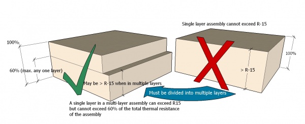

7.1.4. Conventionally Insulated Systems
(The requirements in Subsection 7.1.3., "All Systems", shall be read together with the following articles)
7.1.4.1. Reuse of Insulation for Membrane Replacement
- When a roof is specified for membrane replacement only, the existing insulation may be left in place (Subject to the requirements in Article 1.1.4.3.), but will be excluded from coverage under the Guarantee.
7.1.4.2. Protection of Heat-sensitive Insulation
- When heat-sensitive insulation is used in the primary thermal assembly, it must be covered with a heat-resistant insulation at least 50.8 mm (2”) thick (See Note A-7.1.4.2.).
7.1.4.3. Tapered Insulation and Crickets
- Tapered insulation that is heat-sensitive and manufactured to cover the entire roof area (commonly referred to as a full slope or taper package) must be installed beneath at least one layer of flat board heat-resistant insulation with a minimum thickness of 50.8 mm (2”).
- Tapered insulation
- may be located anywhere within the roof system,
- may be used in calculating the overall thermal performance of the insulation assembly but this is at the discretion of the Design Authority (See Note A-7.1.3.4.), and
- must be installed in multiple soldiered layers when the overall thickness of the tapered insulation assembly is greater than 152.4 mm (6”).
- Crickets that provide no thermal resistance value to the roof system and are used only to promote drainage over limited areas of the roof
- should be manufactured of heat-resistant insulation, but when crickets are manufactured from heat-sensitive insulation they should be covered with a layer of heat-resistant insulation at least 50.8 mm (2") thick, and
- may be installed directly over a roof deck, although this is not recommended (See Section 8.1., "Design", for overlay requirements).
7.1.4.4. Insulating Drain Sumps
- To minimize condensation around drains, drain sumps should be adequately insulated for the regional location of the building, regardless of how the average thermal resistance for the roof system is calculated (See Article 11.1.3.1., "Principles of Design").
7.1.4.5. Use of Mineral Fibre Insulation
- Bitumen-coated mineral fibre insulation
- may be secured with adhesive (See Figure 7.1.4.5.-A),
- may be secured with screw-type fasteners and plates, but this is permissible only when the insulation is subsequently covered with a suitable insulation overlay panel (See Figure 7.1.4.5.-B, Figure 7.1.4.5.-D, Figure 7.1.4.5.-G, and Figure 7.1.4.5.-H; also Article 8.1.4.2.),
- may be installed in multiple layers,
- must be the top layer when multiple layers of mineral fibre insulation are specified (See Figure 7.1.4.5.-C), and
- must be covered with a suitable insulation overlay panel when mechanically fastened through the top-most surface or when supporting an overburden (See Figure 7.1.4.5.-E, Figure 7.1.4.5.-F, Figure 7.1.4.5.-G, and Figure 7.1.4.5.-H; also refer to Article 8.1.4.2. concerning required overlays and use under overburden).
Figure 7.1.4.5.-A Use of Mineral Fibre Insulation
One Layer (AD*)
Forming Part of Clause 7.1.4.5.(1)(1)
(Click to expand)Figure 7.1.4.5.-B Use of Mineral Fibre Insulation
One Layer (MF*)
Forming Part of Clause 7.1.4.5.(1)(2)
(Click to expand)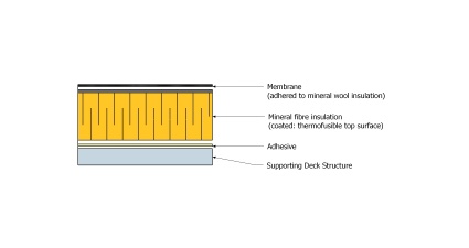
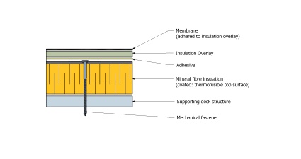
Figure 7.1.4.5.-C Use of Mineral Fibre Insulation
Two Layers (AD*)
Forming Part of Clause 7.1.4.5.(1)(4)
(Click to expand)Figure 7.1.4.5.-D Use of Mineral Fibre Insulation
Two Layers (HYB*)
Forming Part of Clause 7.1.4.5.(1)(2)
(Click to expand)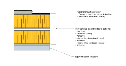

Figure 7.1.4.5.-E Use of Mineral Fibre Insulation
Two Layers (MF*)
Forming Part of Clause 7.1.4.5.(1)(5)
(Click to expand)Figure 7.1.4.5.-F Use of Mineral Fibre Insulation
Two Layers (AD* + Overburden(
Forming Part of Clause 7.1.4.5.(1)(5)
(Click to expand)
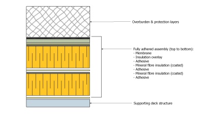
Figure 7.1.4.5.-G Use of Mineral Fibre Insulation
Two Layers (HYB* + Overburden)
Forming Part of Clause 7.1.4.5.(1)(5)
(Click to expand)Figure 7.1.4.5.-H Use of Mineral Fibre Insulation
Two Layers (MF* + Overburden)
Forming Part of Clause 7.1.4.5.(1)(5)
(Click to expand)
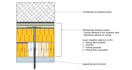
- * MF = Mechanically Fastened; AD = Adhered; HYB = Hybrid Securement
- When bitumen-coated mineral fibre insulation is adhered, torch-applied bituminous membranes may be applied directly to the top insulation panel; the use of an insulation overlay is optional.
- Uncoated mineral fibre insulation panels
- may be installed in multiple layers, but shall be located below other insulation (bitumen-coated mineral fibre, or as permitted by the manufacturer), and
- shall be secured only by mechanically fastening (Adhered, uncoated mineral fibre insulation is not permissible; see Figure 7.1.4.5.-E).


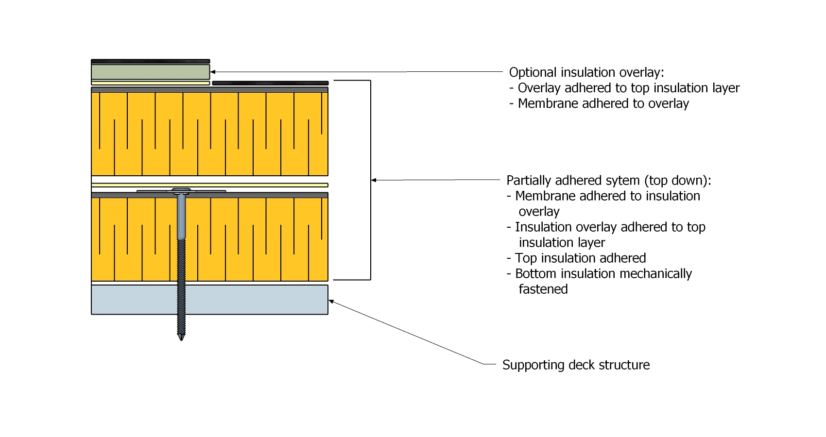
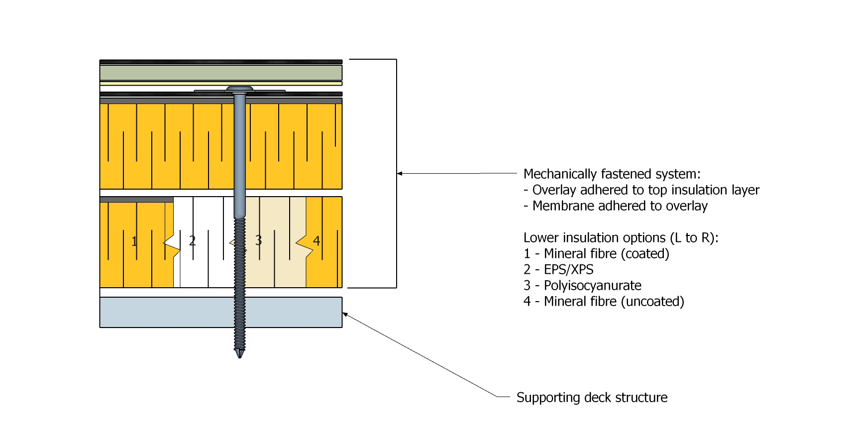

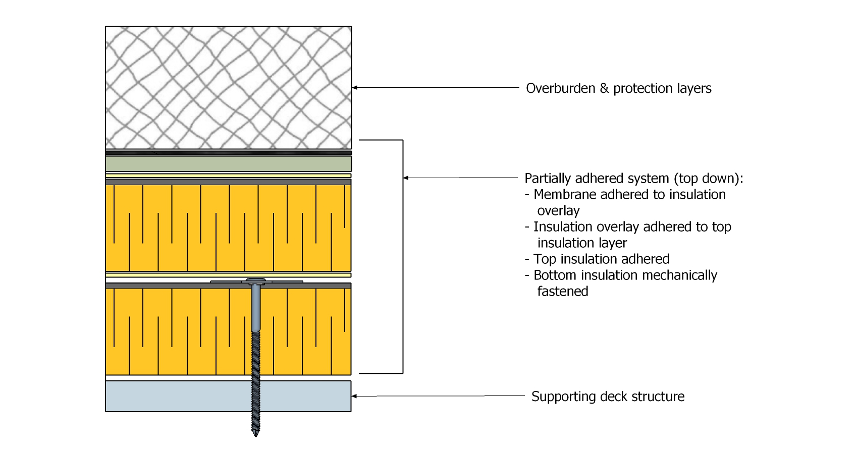

7.1.5. Uninsulated Systems
(The requirements in Subsection 7.1.3., "All Systems", shall be read together with the following articles)
7.1.5.1. Use of Crickets
- Crickets
- should be manufactured of heat-resistant insulation, but when crickets are manufactured from heat-sensitive insulation they should be covered with a layer of heat-resistant insulation at least 50.8 mm (2") thick.
- may be installed directly over a roof deck, although this is not recommended (See Section 8.1., "Design", for overlay requirements).
7.1.5.2. Waterproofing Roof Systems on Uninsulated, Vented Wood-Frame Structures
(See Note A-7.1.5.2. )
- When designing a new or replacement roof system on a vented wood-frame structure, the Design Authority may consider adding heat-resistant insulation (min. R-5) above the deck to reduce or eliminate condensation (See the recent BC Housing Builder Insight publication (Number 21), "Retrofit and Renewal of Low Slope Vented Wood-Frame Roofs", released May 2025). See also Sentence 9.1.3.1.(4) .
7.1.6. Protected Roof Systems
(The requirements in Subsection 7.1.3., "All Systems", shall be read together with the following articles)
7.1.6.1. Insulation Selection
- Only extruded polystyrene insulation (XPS) may be specified for a protected roof system.
7.1.6.2. Drainage Mats and Filter Fabric
- At least one drainage layer is required in a protected membrane roof system, either above or below the XPS insulation, but
- when openings in walls or roof penetrations provide less than 203.2 mm (8”) of clearance, the filtration layer must be water-permeable and the drainage layer shall be below the XPS insulation, to lower the drainage plane and minimize leaks into the building, and
- a drainage layer shall be specified above the XPS insulation when any overburden superimposed on the roof system will result in a “vapour-closed” condition (i.e., a vegetated roof system or an impermeable wearing course).
- Subject to the conditions in Sentence (1), a drainage layer below the XPS insulation in a vegetated roof assembly may be omitted (Sentence 6.1.3.1.(5), “RGC Standard for Vegetated Roofs”).
- Filter fabric must be specified to cover XPS insulation, to
- contain the insulation and thereby prevent ‘insulation stacking’ (displacement) when insulation boards become buoyant in water, and
- prevent fines from settling at the membrane level and filling the voids between insulation board joints.
Section 7.2. Materials
(See Division C, "Accepted Materials")
7.2.1. Material Properties
7.2.1.1. General
- Only insulation boards accepted for use in the RoofStar Guarantee Program, and acceptable to the membrane manufacturer, may be used to qualify for a RoofStar Guarantee.
- The requirement to use on RoofStar-accepted board insulation extends to insulation used in Tested Assemblies (See Article 3.2.1.1., "Substituting Materials Used in a Tested Assembly").
- All insulation types shall have a minimum compressive strength of 110 KPa (20 psi) when installed without a cover board under mechanically attached membranes.
7.2.1.2. Material Dimensions
- The maximum width and length of insulation boards
- installed with adhesive shall be 1219.2 mm (48") (See also Article 7.3.3.1.), and
- installed with mechanical fasteners is limited only by the manufacturer.
- Insulation installed directly over a fluted steel deck must be thick enough to span the flutes under live loads, without risk of cracking or breakage.
- While minimal insulation panel thicknesses are permissible for some designs, some materials are by their nature breakable, and therefore the Design Authority should consider the constructability of the roof system from a material handling perspective and consider specifying a thicker panel.
7.2.1.3. Drainage Mats
- Drainage mats used in protected membrane roof assemblies, or used where overburden superimposed on the roof assembly requires an additional drainage layer, shall conform to the requirements in Article 14.2.1.4.
- Drainage mats that form part of a vegetated roof assembly shall conform to the requirements in Article 6.2.1.2.of the “RGC Standard for Vegetated Roofs”.
7.2.1.4. Filter Fabric
- Filter fabrics for protected membrane roof assemblies shall conform to the requirements in Article 14.2.1.6..
7.2.2. Suitability of Insulation
7.2.2.1. Extruded Polystyrene Insulation
- Extruded polystyrene insulation ("XPS") is heat-sensitive and
- shall conform to CAN/CGSB-51.20-M87, "Thermal Insulation, Polystyrene, Boards and Pipe Covering", for Type 4 insulation, and to ASTM C578, "Standard Specification for Rigid, Cellular Polystyrene Thermal Insulation",
- may be used in a conventionally insulated roof system, and
- is the only insulation that may be specified and installed in a protected roof system.
7.2.2.2. Expanded Polystyrene Insulation
- Expanded polystyrene ("EPS") is heat-sensitive and
- shall conform to ASTM C578, "Standard Specification for Rigid, Cellular Polystyrene Thermal Insulation", and
- shall be specified and installed only in a conventionally insulated roof system, or as crickets in an uninsulated roof system (See also Article 7.1.4.3.).
7.2.2.3. Polyisocyanurate Insulation
(See Note A-7.2.2.3.)
- Polyisocyanurate insulation ("Polyiso") is heat-resistant and
- shall conform to CAN/ULC-S704, "Standard for Thermal Insulation, Polyurethane and Polyisocyanurate, Boards, Faced", and to ASTM C-1289, "Standard Specification for Faced Rigid Cellular Polyisocyanurate Thermal Insulation Board",
- shall be manufactured with non-organic facers, and
- shall be labeled to identify the manufacturer and the date of manufacture.
7.2.2.4. Mineral Fibre Insulation
- Mineral fibre insulation ("Mineral wool") is heat-resistant and
- shall conform to ASTM C726-17, "Standard Specification for Mineral Wool Roof Insulation Board", and
- shall be specified and installed only in a conventionally insulated roof system.
7.2.2.5. Spray Foam Insulation
- Closed-cell Spray Foam insulation (medium density) shall conform to either CAN/ULC-S705.1, "STANDARD FOR THERMAL INSULATION – SPRAY APPLIED RIGID POLYURETHANE FOAM, MEDIUM DENSITY – MATERIAL SPECIFICATION" (latest edition) or CAN/ULC-S711.1, “STANDARD FOR BEAD-APPLIED TWO COMPONENT POLYURETHANE AIR SEALANT FOAM, PART 1: MATERIAL SPECIFICATION” (latest edition) (Note: the applicable standard depends on the application) and may, when appropriate, serve as a vapour retarder or sealant .
- Open-cell Spray Foam insulation (low-density and commonly purchased off-the-shelf) shall conform to CAN/ULC S710.1, “STANDARD FOR BEAD-APPLIED ONE COMPONENT POLYURETHANE AIR SEALANT FOAM, PART 1: MATERIAL SPECIFICATION” (latest edition) and is permissible only for filling minor gaps between insulation panels or around penetrations, when the insulation assembly is offset and staggered in keeping with Article 7.3.2.2.; it is not suitable for, and may not be used to, reseal (repair) a breach in the air or vapour control layers.
Section 7.3. Application
7.3.1. Guarantee Term Requirements
7.3.1.1. RoofStar 5-year Guarantee and RoofStar 10-year Guarantee
- To qualify for a RoofStar 5-year Guarantee or RoofStar 10-year Guarantee, all projects shall comply with the requirements in this Part.
7.3.1.2. RoofStar 15-Year Guarantees
- To qualify for a RoofStar 15-year Guarantee, all projects shall comply with the requirements in this Part for a RoofStar 5-year Guarantee or RoofStar 10-year Guarantee, and shall
- incorporate crickets at all curbs and sleepers that impede drainage or are wider or longer than 1219.2 mm (48”), and
- incorporate an insulation overlay for all insulated systems (regardless of the insulation type) that must
- be at least 6.35 mm (1/4”) thick, and
- possess a compressive strength of at least 690 kPa (100 psi) (Ref. Article 8.1.2.1.).
7.3.2. All Systems
7.3.2.1. Procurement of Insulation
- All insulation, except insulation that may be specified for re-use (See Article 7.1.3.2.), must be supplied and installed by the Contractor.
7.3.2.2. Alignment, Sizing, and Support
- Insulation boards
- must be clean, and dry to the touch,
- must be firmly supported,
- should be square and should make firm, full contact with adjacent panels,
- must be installed with the appropriate grade of expanding spray foam applied to gaps greater than 6.35 mm (1/4”) (this requirement does not apply to extruded polystyrene (XPS) installed in a protected roof system), and
- shall not be soldiered and must be laterally offset at least 304.8 mm (12") in two directions, both for adjacent layers and for adjacent row; a minus offset tolerance of 50.8 mm (2") maximum is permissible (See Figure 7.3.2.2.-A).
- Offsets are not required for
- sloped insulation boards that are generally installed soldiered fashion to adjacent rows, and
- the first layer of overlay board, installed on top of heat-sensitive insulation, which may be soldiered to facilitate joint taping.
Figure 7.3.2.2.-A Offset and Staggered Layering in Field
Forming Part of Clause 7.3.2.2.(1)(4)
(Click to expand illustration)
- On exterior insulated walls, insulation joints at the roof-wall interface must be offset and staggered to eliminate thermal bridging (See Figure 7.3.2.2.-B).
Figure 7.3.2.2.-B Offset and Staggered Layering at Wall
Forming Part of Clause 7.3.2.2.(3)
(Click to expand illustration)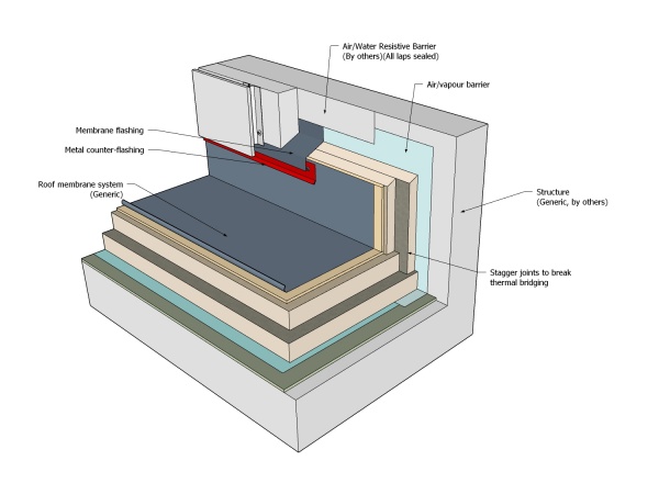
- Where penetrations or their flashings pass through an insulation system, any minor voids less than 25.4 mm (1”) around them must be insulated with a spray foam insulation conforming to the material requirements in Article 7.2.2.5., to reduce the potential for condensation.
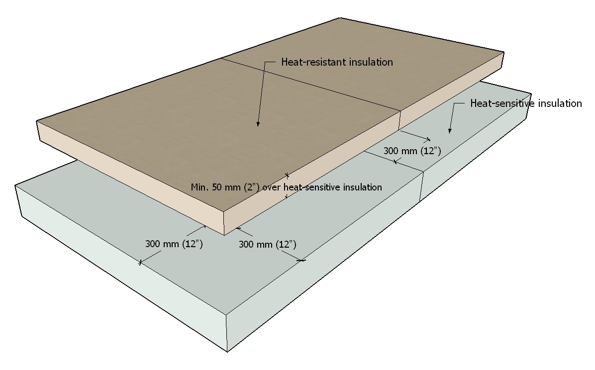

7.3.2.3. Insulation Securement
- Insulation securement shall conform to the specified design for the roof assembly, calculated to resist the Specified Wind Loads for the roof system.
- Mineral fibre insulation shall be installed and secured to comply with the requirements and restrictions in Article 7.1.4.5., "Use of Mineral Fibre Insulation".
7.3.2.4. Protection of Heat-sensitive Insulation
- Heat-sensitive insulation must be protected from high temperatures, both during construction and when placed in service, and therefore it must be overlaid with heat-resistant insulation no less than 50.8 mm (2") thick (see Article 7.1.4.2.).
7.3.3. Conventionally Insulated Systems
(The requirements in Subsection 7.3.2., "All Systems", shall be read together with the following articles)
7.3.3.1. Adhesive-applied Insulation
- Unless specified otherwise by a Tested Assembly or in an engineered specification (see Article 3.3.2.2, "Securing Systems with Adhesives"), when insulation components are installed with adhesive,
- the maximum width and length of an insulation panel shall be 1219.2 mm (48"), and
- the maximum length of any insulation overlay panel shall be 2438.4 mm (96").
- When extruded polystyrene insulation is adhered with a two-component low-rise polyurethane foam adhesive, the faces of the insulation board must be roughened by planing to achieve optimal adhesion.
- Two-component low-rise polyurethane foam adhesive ribbons must be applied
- to a clean, dry, and contaminant-free surface,
- in parallel runs or in a Z-pattern,
- no more than 152.4 mm (6”) from any edge of the board and spaced no more than 304.8 mm (12”) apart, and
- in ribbon widths specified by the adhesive manufacturer or, in the absence of manufacturer requirements, 19.05 mm (3/4”) wide.
- Roof system components adhered with two-component low-rise polyurethane foam must be
- installed immediately in wet adhesive (before a surface skin develops), and
- properly placed and weighted in wet adhesive until cured.
7.3.3.2. Insulation Adhered with Hot Bitumen
- Hot bitumen used to adhere a roof system
- must be applied at minimum rates and temperatures based on the type of product, as published by the material manufacturer and in the Standard for Built-up Roof (BUR) Systems, and
- may be applied on slopes up to 1/2:12 (For steeper slopes, select a different method of securement).
7.3.4. Reserved
7.3.5. Protected Roof Systems
(The requirements in Subsection 7.3.2., "All Systems", shall be read together with the following articles)
7.3.5.1. Sequencing of Work
- Insulation installed against walls or curbs must be separated from roof membranes with a non-bonding drainage mat or slip sheet.
- Insulation must be secured and protected immediately after installation.
7.3.5.2. Drainage Mats
(See also Part 11, "Drainage")
- At least one drainage layer is required in a protected membrane roof system and its location within the system shall conform to the design requirements in Sentence 7.1.6.2.(1).
- A drainage mat must be installed below the XPS insulation.
- A second drainage layer may be installed above the insulation but is at the discretion of the Design Authority.
- If a second drainage layer is specified, a vertical separation space measuring at least 12.7 mm (1/2″) must be preserved between the drainage layer and any ballast or overburden, to permit airflow and to assist in leveling.
- Specialized proprietary drainage products must be acceptable to the membrane manufacturer.
- Ballast guards must be installed around all roof drains.
7.3.5.3. Filter Fabric
- Fabric filter mats must be
- installed loose-laid (un-bonded) over the insulation and below any type of ballast or roof covering,
- overlapped at all edges a minimum of 304.8 mm (12”),
- at least 2438.4 mm x 2438.4 mm (96" x 96") in size, and
- slit to fit over roof penetrations or cut out around roof drains and other openings.
- Filter fabric must extend up perimeter edges and curbs and must be placed loose (unattached) under metal counter flashings or wall finishes.
- When the filtration layer is part of a vegetated roof assembly, the filtration layer shall conform to Article 10.3.2.7.of the “RGC Standard for Vegetated Roofs”.
Part 8 - Insulation Overlays
Section 8.1. Design
(See Note A-8.1)
8.1.1. General
8.1.1.1. Scope
- The scope of this Part and the Standard shall be as described in Division A, Part 1.
8.1.1.2. Defined Terms
- Words that appear in italics are defined in the Glossary.
8.1.2. Guarantee Term Requirements
8.1.2.1. RoofStar 5-year Guarantee and RoofStar 10-year Guarantee
- To qualify for a RoofStar 5-year Guarantee or RoofStar 10-year Guarantee, all projects shall comply with the requirements in this Part.
8.1.2.2. RoofStar 15-Year Guarantee
- To qualify for a RoofStar 15-year Guarantee, all projects shall comply with the requirements in this Part for a RoofStar 5-year Guarantee or RoofStar 10-year Guarantee, and shall
- incorporate an insulation overlay on all "conventionally insulated systems, regardless of the insulation type, that must
- be at least 6.35 mm (1/4”) thick, and
- possess a compressive strength of at least 690 kPa (100 psi).
- incorporate an insulation overlay on all "conventionally insulated systems, regardless of the insulation type, that must
8.1.2.3. RoofStar Vegetated Roof Guarantee
- To qualify for a RoofStar Vegetated Roof Guarantee, the supporting roof assembly shall
- comply with the requirements in this Part for a RoofStar 5-year Guarantee, RoofStar 10-year Guarantee, or a RoofStar 15-year Guarantee,
- be acceptable to the manufacturer as support for a vegetated roof system, and
- comply with the related requirements in the “RGC Standard for Vegetated Roofs”.
8.1.3. Reserved
8.1.4. Conventionally Insulated Systems
8.1.4.1. Required Use of Insulation Overlays
- Except as provided in Sentence (4), all conventionally insulated roof systems must incorporate one layer of an accepted insulation overlay to cover all flat or tapered insulation panels, installed on any plane, whenever any one of the following conditions apply:
- The compressive strength of the specified insulation is less than 110 KPa (20 psi),
- Specified membranes are adhered or heat-welded (see Table 9.2.1.1.), or
- Overburden will be superimposed on the roof system.
- When a conventionally insulated roof system supports overburden, the overlay panels must be
- adhered to the insulation (mechanical fastening is not permissible),
- selected from the tables in Division C for
- asphaltic panels (with or without factory-laminated base sheet membranes),
- moisture resistant gypsum-based panels,
- panels made of high-density insulation, or
- high-density insulation panels with factory-laminated membranes, and
- capable of supporting any superimposed loads on the exposed membrane, without compression or distortion of the roof system or any one of its components (See also Article 14.1.3.2., "Loads").
- Notwithstanding the requirements in Sentence (2), when the roof assembly supports a vegetated roof system the overlay must be at least 12.7 mm (1/2”) thick and capably resist compression loads equal to or greater than 552 kPa (80 psi) (“RGC Standard for Vegetated Roofs”, Clause 1.1.3.1.(2)(2)).
- Except where an insulation overlay is required in Sentence (2), an insulation overlay is optional (not required) when the membrane is self-adhered and the following conditions have been satisfied:
- The specified membrane is expressly accepted by the Guarantor for application directly on a specific insulation board without the use of an overlay, and
- The specified membrane is expressly approved (in published literature) by the manufacturer for application directly to a specific insulation panel.
- Crickets made of heat-sensitive insulation, specified for and installed in a membrane system applied with hot bitumen, shall be covered with no less than
- one layer of an accepted overlay panel, provided the panel thickness is at least 12.7 mm (1/2") and the joints between panels are sealed with the manufacturer’s approved self-adhered membrane or tape, or
- two layers of an accepted overlay panel, when the thickness of the panel is at least 4.76 mm (3/16").
8.1.4.2. Use Over Mineral Fibre Insulation
(See also Article 7.1.4.5.)
- Mineral fibre insulation must be overlaid with a moisture-resistant fibreglass-faced silicon treated gypsum core board measuring at least 12.7 mm (1/2") thick
- when the insulation is mechanically fastened, or
- when it will support overburden.
- An insulation overlay is not required when torch-applied membranes are applied directly to the bitumen coating of mineral fibre insulation that has been secured with adhesives.
Section 8.2. Materials
(See Division C, "Accepted Materials")
8.2.1. Material Properties
8.2.1.1. Insulation Overlay Dimensions
- Regardless of the type of insulation overlay, the overall thickness of insulation overlay boards shall not exceed 50.8 mm (2”) (See minimum allowable thicknesses are shown in Table 8.2.1.1.).
- Asphalt-coated fibreboard roof insulation adhered with hot asphalt or an asphalt-based adhesive must be asphalt-coated on the top and bottom surface (Minimum coated two-sides).
- Fire guard tape must be 152.4 mm (6”) wide
- self-adhering modified bituminous tape acceptable to the membrane manufacturer, or
- Type IV fibreglass felt or No. 15 organic felt, applied with hot bitumen or cold adhesive.
Table 8.2.1.1..
Insulation Overlay Dimensions
Forming Part of Article 8.2.1.1.
| Overlay Type | Minimum Thickness - mm (in.) |
|---|---|
| Moisture resistant fibreglass-faced silicon treated gypsum core | 6.35 (1/4") |
| High-density insulation | 12.7 (1/2") |
| Fibreboard | As listed in this Manual |
| Mineral wool | As listed in this Manual |
Section 8.3. Application
8.3.1. Guarantee Term Requirements
8.3.1.1. RoofStar 5-year Guarantee and RoofStar 10-year Guarantee
- To qualify for a RoofStar 5-year Guarantee or RoofStar 10-year Guarantee, all projects shall comply with the requirements in this Part.
8.3.1.2. RoofStar 15-Year Guarantees
- To qualify for a RoofStar 15-year Guarantee, all projects (except as noted in Sentence (2)) shall comply with the requirements in this Part for a RoofStar 5-year Guarantee or RoofStar 10-year Guarantee, and shall
- incorporate an insulation overlay on all insulated systems (regardless of the insulation type) that must
- be at least 6.36 mm (1/4”) thick, and
- possess a compressive strength of at least 690 kPa (100 psi).
- incorporate an insulation overlay on all insulated systems (regardless of the insulation type) that must
- When a vegetated roof system is constructed on a conventionally insulated roof assembly, the insulation overlay shall conform to the requirements in Sentence 8.1.4.1.(3).
8.3.2. Reserved
8.3.3. Conventionally Insulated Systems
8.3.2.1. Alignment of Overlays
- The Contractor shall ensure that the selection and application of insulation overlays conforms to the Design requirements in Section 8.1. of this Part.
- Fibreboard shall not be used as an insulation overlay beneath torch-applied membranes.
- Insulation overlays
- should be square and should make firm, full contact with adjacent panels unless specified otherwise by the manufacturer, and
- must be offset at least 304.8 mm (12") from the joints of the insulation layer; a minus offset tolerance of 50.8 mm (2") maximum is permissible.
- All insulation overlay boards must be offset from insulation joints by at least 304.8 mm (12”) and shall be offset from adjacent and underlying overlay boards by at least 304.8 mm (12”) (Figure 8.3.2.1.-A).
- While insulation overlays with a laminated base sheet membrane shall be offset and staggered from the insulation joints, they may be installed soldier-fashioned with each other, but only when this is permissible in the application literature published by the manufacturer.
Figure 8.3.2.1.-A Offset and Staggered Insulation and Overlays
Forming Part of Article 8.3.2.1.
(Click to expand illustration)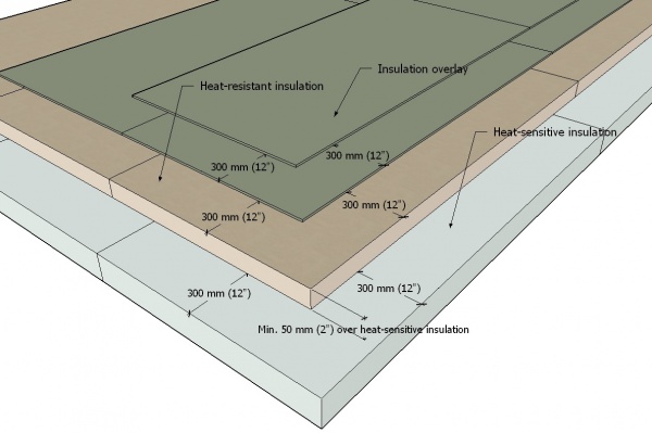

8.3.2.2. Mechanical Securement
- When mechanically attaching insulation overlay boards, the insulation and overlay boards may be fastened together as one assembly.
- Unless otherwise indicated by the system requirements in a Tested Assembly, follow the fastener patterns set out in Article 3.3.2.1.
- When a membrane-laminated overlay is mechanically fastened over insulation, fasteners and plates used in the field of each panel must be covered with polyester or composite-reinforced membrane patches that extend past the edge of each plate at least 50.8 mm (2”).
8.3.2.3. Adhered Securement
- Adhered overlays must conform to the design requirements in Section 8.1. of this Part.
- Roof system components adhered with two-component low-rise polyurethane foam must be
- installed immediately in wet adhesive (before a surface skin develops), applied
- to a clean, dry and contaminant-free surface,
- in parallel runs or in a Z-pattern, no more than 152.4 mm (6”) from any edge of the board and spaced no more than 304.8 mm (12”) apart, and
- in ribbon widths specified by the adhesive manufacturer or, in the absence of manufacturer requirements, 19.05 mm (3/4”) wide, and
- properly placed and weighted in wet adhesive until cured.
- installed immediately in wet adhesive (before a surface skin develops), applied
- Hot bitumen used to adhere a roof assembly
- must be applied at minimum rates and temperatures published by the manufacturer for the type of bitumen used, and
- may be applied on slopes up to 1/2:12 (for steeper slopes, select a different method of securement).
Part 9 - Roof Field (Membrane Systems)
Section 9.1. Design
9.1.1. General
9.1.1.1. Scope
- The scope of this Part and the Standard shall be as described in Division A, Part 1.
9.1.1.2. Defined Terms
- Words that appear in italics are defined in the Glossary. Additionally, the following terms are used in this Part:
- Manufacturer means the manufacturer of the primary roof covering, unless stated otherwise.
- Parallel to Slope means the direction parallel to the angle of a sloped plane.
9.1.2. Guarantee Term Requirements
9.1.2.1. RoofStar 5-year Guarantee Guarantee and RoofStar 10-year Guarantee
- To qualify for a RoofStar 5-year Guarantee or RoofStar 10-year Guarantee, all projects shall comply with the requirements in this Part.
9.1.2.2. RoofStar 15-Year Guarantee
- To qualify for a RoofStar 15-year Guarantee, all projects shall comply with the requirements in this Part for a RoofStar 5-year Guarantee or RoofStar 10-year Guarantee, and shall
- be constructed with membranes conforming to the RoofStar 15-Year Guarantee criteria in Table 9.2.1.1.
9.1.2.3. RoofStar Vegetated Roof Guarantee
- To qualify for a RoofStar Vegetated Roof Guarantee, the supporting roof assembly shall
- comply with the requirements in this Part for a RoofStar 5-year Guarantee, RoofStar 10-year Guarantee, or a RoofStar 15-year Guarantee,
- be acceptable to the manufacturer as support for a vegetated roof system (with consideration to added hydrostatic pressure – see Article 1.1.4.1. in the “RGC Standard for Vegetated Roofs”), and
- comply with the related requirements in the “RGC Standard for Vegetated Roofs”.
9.1.3. All Systems
9.1.3.1. General Requirements
- Any roof areas with a slope less than 1:16 (3/4" in 12") require 2 ply membrane assemblies.
- All SBS-modified bituminous membrane roofs shall be designed to satisfy the requirements of the Code and the requirements in Part 3 of this Standard.
- The specifications, details, and installation techniques must conform to the membrane manufacturer's requirements.
- New and replacement roof systems on wood-framed vented roof assemblies should be designed in alignment with Article 7.1.5.2., to address possible condensation on the underside of the roof deck .
- When the Design Authority intends to recover a roof membrane (recovering is a type of roof replacement), the design must conform to the requirements in Article 1.1.4.4. and Article 1.3.3.4.; recovering is permitted only with a written Variance issued by the Guarantor prior to tendering .
- Membranes must be selected for their
- composition, both in terms of thickness and reinforcement,
- performance characteristics in relation to the intended use of the roof, as for example puncture resistance or reflectivity and reduced heat absorption,
- application methodology, which may be limited by the type of supporting deck or substrate to which it will be applied, and
- seasonal applications (summer and winter grades).
- Single ply modified bituminous membranes require a minimum slope of 1:16 (3/4” in 12”).
- Membranes may not be adhered to lightweight insulation concrete unless expressly permitted by the manufacturer.
9.1.3.2. Control Joints (Roof Dividers)
- When control joints (roof dividers) are recommended or required by the manufacturer, or are deemed necessary by the Design Authority, they must be designed following the requirements in Article 10.1.6.2.
9.1.3.3. Securement
(See Note A-9.1.3.3.)
- The roof system must be secured to resist displacement by Specified Wind Loads, and therefore the requirements in this Article shall be read together with the requirements in Part 3 of this Standard.
- When membranes are mechanically fastened, only base membranes designed for in-seam screw-type fasteners may qualify; nail-applied membranes are not permissible.
- When the designed slope of the roof exceeds 1:6 (2” in 12”), and either or both membranes are self-adhered, the head-lap of a full or partial membrane run, installed parallel to the slope, must be secured with at least three (3) mechanical fasteners and plates equally spaced across its width.
- When the membrane is specified to run perpendicular to the slope, the up-slope seam must be mechanically fastened with screws and plates no more than 609.6 mm (24”) O.C.
- Primary roof membranes may not be directly adhered to a wood deck.
- When the roof slope exceeds 1:24 (1/2” in 12”), only cap membranes installed by methods other than with hot bitumen may be specified.
- Single-ply SBS-modified bituminous membranes may be used only when the roof slope is greater than 1:16 (¾” in 12”), and may be adhered, self-adhered, mechanically fastened, or torch-applied to the substrate for which they are designed and specified.
9.1.3.4. Membrane Protection
- Installed membranes must be protected from damage caused by
- any walkway surface,
- work performed concurrently or subsequently by other trades (the Design Authority is strongly urged to direct the work of other trades through specific, explicit directives in the design specifications), and
- chemicals or other contaminants that may adversely impact the roof membrane or other system components, including (without limitation)
- animal or vegetable grease,
- hot pipes (release valves),
- petroleum products or bi-products, and
- miscellaneous fluids from equipment (See also Article 12.3.2.6. for application of reinforced liquid membrane flashing around roof penetrations).
- Membranes should be protected from
- pool or garden chemicals and fertilizers,
- pet urine,
- bird excrement, and
- refrigerants.
- Where it is desirable for the field membrane to resist the damaging effects of grease, oils or other contaminants, the Design Authority should consider specifying a Roofstar-accepted, fleece-reinforced 2-component catalyzed polymethyl methacrylate (PMMA) liquid membrane (See also Article 9.3.3.5.).
- Roof membranes that are exposed to sunlight reflected off adjacent glazing and metal cladding or framework (such as window mullions) should be selected for their ability to accommodate elevated temperatures, or should be protected
- with overburden materials, such as pavers or gravel, or
- by overhangs that shade reflective wall surfaces and glazing (See Note A-9.1.3.4.).
9.1.3.5. Walkways
- When conventionally insulated and uninsulated systems will be accessed at least once per month for maintenance of serviceable equipment, the design must incorporate designated walkways
- to protect the primary membrane at roof access points, equipment service locations and along travel routes,
- that facilitate drainage and drying (pedestals and other paver supports provide airflow for drying surfaces and assist in leveling; they should not impede the flow of water or air and should uniformly distribute the dead load of pavers and predicted live loads), and
- that are properly secured against movement by wind.
- The membrane must be suitably protected from mechanical damage by walkway surfaces.
- Paver walkway surfaces must be suitably supported in keeping with Article 14.1.3.11. and Article 14.3.2.5., "Wearing Surfaces".
- Designated walkways may be specified using a proprietary coating (See also Division A, Article 3.2.1.2.), or may be superimposed on the membrane surface but must be suitably supported in keeping with Article 14.1.3.11. and 14.3.2.5., "Wearing Surfaces".
- Membrane walkways constructed with a third ply are permissible but are not considered part of the roof system and therefore are not covered by the Guarantee.
9.1.4. Conventionally Insulated Systems
(The requirements in Subsection 9.1.3., "All Systems", shall be read together with the following articles)
9.1.4.1. General Requirements
- All conventionally insulated roof systems must conform to the requirements in Article 3.1.4.1., and to Part 3 generally.
- Only PARS and AARS assemblies are permitted when a conventionally insulated roof system, or a portion of it, is designed to support any type of load; pavers supported by pedestals are an exception (this limitation must be read together with the requirements in Part 14).
9.1.4.2. Warning Zones
- Fall protection warning zones (see WorkSafeBC Regulations and related materials) may be designed to utilize
- primary roof membranes in contrasting colours,
- a "sacrificial" third ply installed over the primary cap membrane (Ref. Division A, Article 3.2.1.2.), or
- a proprietary coating.
9.1.5. Uninsulated Systems
(The requirements in Subsection 9.1.3., "All Systems", shall be read together with the following articles)
9.1.5.1. General Requirements
- All uninsulated roof systems must satisfy the requirements of the Building Code and Part 3 of this Standard, and shall be (when applicable)
- a Tested Assembly,
- an Assembly with Proven Past Performance, or
- an assembly with custom-engineered securement.
- When a roof system installed on a concrete deck or concrete topping is uninsulated, the base membrane must be vented to mitigate the effects of vapour drive from the concrete.
- Membranes may not be fully adhered or torch-applied to a wood deck.
- Membranes specified for application over a wood deck shall be
- fully adhered to a mechanically attached, RoofStar-accepted deck overlay board,
- "vented" (semi-adhered), or
- mechanically fastened.
- New and replacement roof systems on wood-framed vented roof assemblies should be designed in alignment with Article 7.1.5.2., to avoid possible condensation on the underside of the roof deck; darker granules colours, which absorb more solar heat, are recommended.
9.1.5.2. Warning Zones
- The requirements and recommendations in Article 9.1.4.2. shall be applied and considered for uninsulated roof systems.
9.1.6. Protected Roof Systems
(The requirements in Subsection 9.1.3., "All Systems", shall be read together with the following articles)
9.1.6.1. General Requirements
- Only fully adhered membranes may be used in a Protected Membrane Roof System; mechanically attached membranes are not suitable and shall not be used for this application.
- When specifying the top layer in a 2-ply or 3-ply system, use a product with a sanded top surface to prevent bonding with superimposed roof materials (this includes bonding with a root barrier, when a vegetated roof system is specified) or, when specifying a membrane that is film-surfaced, require that the film be ‘defeated’ (usually with a torch) to prevent sloughing, which can block drains; granule-surfaced cap sheet membranes are unnecessary, except where membrane flashing will be exposed to the sun .
- Ballasted systems shall conform to the requirements in Article 3.3.5.1. and Article 9.1.3.3.
Section 9.2. Materials
(See Division C, "Accepted Materials")
9.2.1. Material Properties
9.2.1.1. Membrane Composition, Thickness, and Selection
(See Note A-9.2.1.1.)
- All SBS polymer-modified bituminous membranes must be selected from the list of accepted materials published in Division C of this Manual, and must conform to
- RGC ACWP-MOD (RGC ACCEPTANCE CRITERIA for MANUFACTURED POLYMER-MODIFIED, REINFORCED BITUMINOUS SHEET MEMBRANES Used in Roof Waterproofing and Grade-level Waterproofing Systems), which relies onCSA-A123.23, "Product specification for polymer-modified bitumen sheet, prefabricated and reinforced", and
- the membrane properties in Table 9.2.1.1.
- Base and cap membranes in a 2-ply or 3-Ply SBS polymer-modified bituminous membrane system
- shall each be modified with the same polymer,
- shall each satisfy the minimum thickness requirements in Table 9.2.1.1., and
- when combined as a membrane system, shall together satisfy the minimum combined thickness requirements published in Table 9.2.1.1.
- Oxidized asphalt membranes will be considered as underlay only and must not be counted as one of two plies.
- Notwithstanding the minimum requirements for hot-mopped membranes published in Table 9.2.1.1., the minimum thickness requirements for both the base sheet and cap sheet (irrespective of membrane reinforcement) may be reduced to 2.0 mm, to meet the intent of the requirements in the Table, but only when both membranes are hot-mopped and the combined membrane system is flood-coated with either hot bitumen or the manufacturer’s proprietary material, plus gravel.
- Liquid membranes must be reinforced and accepted for use over a base membrane ply acceptable to the manufacturer of the liquid membrane.
Table 9.2.1.1.
Properties of SBS Polymer Modified Bituminous Membranes
Forming Part of Article 9.2.1.1.
All thicknesses shown are in mm.
"X"means not permissible or not available.
Exposed Roof Systems Protected Roof Systems Grade-level
Water-
proofingConventionally Insulated / Uninsulated Systems Membrane
GuttersPMR
SystemsMechanic-
ally
fastenedHeat-
weldedAdhered Heat-
welded;
Adhesive-
applied;
Self-
adheredHeat-
welded;
AdheredPuncture Resistance Heat-
welded;
AdheredPuncture Resistance Self-
adheredHot-
moppedAdhesive-
appliedPly, Reinforcement, and Type/Grade Guarantee Term mm mm mm mm mm mm mm (N) mm (N) Minimum Combined 2-ply Thickness 5/10 6.00 6.00 X 6.00 X 15 6.50 6.50 X X X Base (Fibreglass) - Type A/Grade 3 5/10 2.30 2.30 2.30 2.20 2.20 X X X X X 15 X 2.50 2.50 2.50 2.50 X X X X X Base (Composite fibreglass) - Type A/Grade 3 5/10 2.30 2.30 2.30 2.20 2.20 2.50 2.20 X 2.20 X 15 X 2.50 2.50 2.50 2.50 2.90 2.50 X X X Base (Polyester) - Type B/Grade 3 5/10 2.50 2.50 2.50 2.20 2.20 2.50 2.20 X 2.20 X 15 X 2.50 2.50 2.50 2.50 2.90 2.50 X X X Base (Composite) - Type C/Grade 3 5/10 2.30 2.30 2.30 2.20 2.20 2.50 2.20 X 2.20 X 15 X 2.50 2.50 2.50 2.50 2.90 2.50 X X X Factory Laminated Base (panel) 5/10 2.20 X 2.20 X X X 15 2.20 X 2.20 X X X Film Cap (Fibreglass) - Type A/Grade 2 or 3 5/10 X 4.00 3.30 3.30 3.30 X X X X X 15 X X X X X X X X X X Film Cap (Polyester) - Type B/Grade 2 or 3 5/10 X 4.00 3.50 3.50 3.50 3.00 3.00 400 3.00 400 15 X 4.00 4.00 4.00 4.00 4.00 3.00 400 X X Film Cap (Composite) - Type C/Grade 2 or 3 5/10 X 4.00 3.30 3.30 3.30 3.00 3.00 400 3.00 400 15 X 4.00 4.00 4.00 4.00 4.00 3.00 400 X X Granule Cap (Fibreglass) - Type A/Grade 1 5/10 X 4.00 3.30 3.30 3.30 X X X X X 15 X X X X X X X X X X Granule Cap (Polyester) - Type B/Grade 1 5/10 X 4.00 3.50 3.50 3.50 3.50 3.00 400 3.00 400 15 X 4.00 4.00 4.00 4.00 4.00 3.00 400 X X Granule Cap (Composite) - Type C/Grade 1 5/10 X 3.30 4.00 3.30 3.30 3.50 3.00 400 3.00 400 15 X 4.00 4.00 4.00 4.00 4.00 3.00 400 X X
9.2.1.2. Fasteners and Adhesives
- Fasteners and adhesives shall conform to the material requirements in Section 3.2.
9.2.1.3. Protection Materials
- When installed membranes require protection, the requirements in Article 14.2.1.2. apply.
9.2.2. Materials Storage and Handling
9.2.2.1. Protection from the Weather
- All uninstalled materials must be protected from weather by properly stacking them above ground, or above the roof surface, in or beneath covers that are weather-resistant and secured against displacement by wind (See also Article 4.2.1.1., "Use of Accepted Materials").
9.2.3. Accessories
9.2.3.1. Accessories Supplied by Membrane Manufacturer
- All membrane accessory components must be supplied by and acceptable to the manufacturer.
Section 9.3. Application
9.3.1. Guarantee Term Requirements
9.3.1.1. RoofStar 5-year Guarantee and RoofStar 10-year Guarantee
- To qualify for a RoofStar 5-year Guarantee or RoofStar 10-year Guarantee, all projects shall comply with the requirements in this Part.
9.3.1.2. RoofStar 15-Year Guarantee
- To qualify for a RoofStar 15-year Guarantee, all projects shall comply with the requirements in this Part for a RoofStar 5-year Guarantee or RoofStar 10-year Guarantee, and shall
- utilize only those membranes listed in Table 9.2.1.1. that qualify for a RoofStar 15-year Guarantee.
9.3.2. All Systems
9.3.2.1. Preparation of Substrate
- All supporting decks must be acceptable to the manufacturer and must be
- made suitable for roofing by others (trades other than the Contractor),
- dimensionally stable,
- structurally sound,
- capable of accommodating roof system component movement,
- clean,
- adequately dry and frost-free (Ref. Subsection 2.1.5., "Roof Decks"),
- reasonably smooth and free of abrupt elevation changes, and
- absolutely free of
- dust,
- dirt,
- voids,
- open cracks,
- sharp projections,
- contaminants,
- objectionable surface treatments,
- laitance (concrete must be “native”),
- oil, and
- grease.
- A properly secured, accepted overlay board is required (Ref. Part 5)
- for any deck that does not meet the deck fastening criteria set out in Article 2.1.5.3., and
- for any deck that cannot be repaired or otherwise made suitable for roofing.
- Substrates must be primed, if required by the manufacturer.
- All plane transitions must be prepared or reinforced in the manner specified by the manufacturer.
- All concrete decks
- must cure at least 28 days before receiving adhered membranes, but this limitation may be reduced if both the building envelope engineer and the manufacturer expressly permit membrane application within the first 28 days after pouring, and their respective signed letters of permission are furnished to the Guarantor forthwith, to be included with the project record ("adhered", as used in this requirement, means fully or intermittently bonding any membrane to the deck with an adhesive, hot asphalt (bitumen), or heat),
- must be finished by others to render a surface profile range suitable to the membrane manufacturer, to facilitate a ‘mechanical bond’ between the substrate and the membrane, and
- constructed with pre-cast panels must be made continuous and even; all side and end-joints must be filled and reinforced according to the manufacturer’s published requirements.
- Plywood decks with cracks or loose knots must be filled or overlaid with plywood (see Article 5.2.1.1.).
- Joints between plywood deck panels must be prepared and reinforced according to the manufacturer’s published requirements.
- Wood decks must be overlaid with an acceptable deck overlay panel when the specified membrane system will be adhered directly to the deck (Ref. Part 5), but an overlay is not required (unless specified by the Design Authority) for
- self-adhered air or vapour controls, or
- mechanically fastened or loose-laid membranes.
- A deck overlay is not required for mass timber decks (see Article 2.1.5.5.) but when an overlay is specified it must be plywood conforming to the material requirements in Article 5.2.1.1.
- If surface drying is required prior to roofing, the deck must be dried with blown air.
9.3.2.2. Preparation of Roofing Materials
- Membranes must be unrolled, prepared, and conditioned for installation, as required by the manufacturer.
9.3.2.3. General Requirements for Membrane Application
- Membranes must be installed according to the manufacturer's published instructions, details, and installation techniques unless exceeded by this Standard.
- Membranes should be installed beginning at the lowest point of the roof.
- All membrane openings at eaves, walls, vents, etc. must be sealed during application to prevent moisture from entering the roof system or between membrane flashing plies.
- Except for the application of picture-framing techniques (see Sub-section 10.3.8., "Alternative Approaches to Sheet Membrane Flashing"), both the base and cap membranes must be installed in a parallel direction (not perpendicular to each other).
- Both the base and cap membranes of a 2-ply un-granulated (smooth) membrane system must be installed separately; installation "shingle fashion" (i.e., 50% lap) is not acceptable except where membrane "back nailing" is required.
- Before any roof covering, structure or equipment is installed, roof membranes must be
- inspected,
- scanned for breaches, when an integrity scan is required by this Standard, and
- free of deficiencies.
- At the end of a day, or when installation must be stopped because of circumstance (such as inclement weather), the new roof system membrane must be temporarily and continuously sealed to ensure the building and any new roof system components are protected from exposure to, and damage by, the weather.
9.3.2.4. Cold and Inclement Weather Application
- Installation during cold weather must follow the membrane manufacturer’s guidelines for storage and membrane conditioning.
9.3.2.5. Securement on Slopes
- Self-adhered membranes installed on slopes exceeding 1:6 (2” in 12”) must conform to Article 9.3.3.1.
9.3.2.6. Membrane Seams
- When the membrane is specified to run parallel to a slope, the up-slope seam must be mechanically fastened with screws and plates no more than 609.6 mm (24”) O.C.
- All membranes must
- overlap adjacent membranes (side laps) at least 76.2 mm (3”),
- overlap the end of the next membrane run at least 152.4 mm (6") (angle-cut the selvedge corner of the underlying membrane as required by the manufacturer), and
- offset adjacent membrane end laps by at least 304.8 mm (12”).
- Membranes shall be installed so that cap membrane end laps are located at least 914.4 mm (36”) from the centre of any roof field drain, except where drain sumps are employed.
- When membranes are mechanically fastened, side laps must be at least 101.6 mm (4”) and cover the fastener plate by at least 50.8 mm (2”).
- Seams must be fully bonded, both along the sides and at the ends of membrane runs.
- All base membrane field seams, regardless of the type of application, must be “buttered” before the end of the working day.
- All cap membranes must exhibit continuous visible bitumen bleed-out along seam edges.
- Cap membrane runs must be offset from the base field membrane seams, according to the membrane manufacturer's published instructions, and centred over drains.
9.3.2.7. Protection of Membranes
- The Contractor, and other trades who use primers for self-adhering membranes typically installed on walls or around doors, window, or other wall penetrations, must protect membranes
- from splashed or dripped primer used to enhance adhesion of self-adhering membranes, as the primer may damage the membranes and cause leaks, and
- from accidental damage, including damage by staged materials, scaffolding, foot and equipment traffic, and anything else that may pose a hazard to the integrity of the membrane.
9.3.2.8. Transitions with Water-shedding Systems
- Where slopes less than 1:16 (3/4" in 12") intersect a water-shedding system, the waterproofing system must be designed to extend up the water-shedding system slope as described in Article 10.3.7.2., using methods conforming to the general application requirements in Article 10.3.2.3.
9.3.2.9. Walkways
- Any walkway pads or supports capable of absorbing solar radiation must be installed on a non-bonding slip sheet, to protect the membrane from damage by heat.
- When pavers are used as the walkway material, they must be
- spaced no closer than 3.18 mm (1/8″),
- supported by non-abrasive pads or proprietary pedestals providing a minimum of 12.7 mm (1/2″) of vertical separation to permit adequate airflow and leveling (Slip sheets under pedestals may be necessary to prevent membrane abrasion), and
- secured against displacement by wind.
- When an additional membrane ply serving as a ‘sacrificial’ walking surface is installed over the completed multi-ply membrane, the 'sacrificial' ply is not considered part of the roof system and therefore is excluded from coverage under the RoofStar Guarantee.
9.3.3. Membrane Application Methods
(The requirements in Subsection 9.3.2., "All Systems", shall be read together with the following articles)
9.3.3.1. Self-adhered and Cold-processed Membranes
(See Note A-9.3.3.1.)
- The installation of self-adhering membranes across the slope of the roof is not recommended.
- Canted edges are required for all self-adhering membranes when the manufacturer requires them.
- When both the base and cap membranes are self-adhered, the cap membrane must be installed on a clean, dry base and both must be completed together on the same workday, according to the manufacturer’s published instructions; phased installation of membranes is not permissible.
- When either or both membranes are self-adhered and the designed slope of the roof
- exceeds 1:6 (2” in 12”) but is no greater than 1:3 (4” in 12”), membrane laps must conform to the general requirements published elsewhere in this Part, but the head-lap of a full or partial membrane run, installed parallel to the slope, must be secured with at least three (3) screw fasteners and plates equally spaced across its width.
- exceeds 1:3 (4” in 12”), membrane laps must conform to the general requirements published elsewhere in this Part, but
- the head-lap of a full or partial membrane run, installed parallel to the slope, must be secured with at least three (3) screw fasteners and plates equally spaced across its width, and
- the side laps must be mechanically fastened with screws and plates spaced no more than 609.6 mm (24”) O.C.
- To ensure even, full contact with the substrate, all self-adhered and cold adhesive-applied field membranes must be fully rolled with a roller weighing at least 34.2 Kg (75 lbs).
- When self-adhesive membranes are
- installed at ambient air temperatures below 10° C, the granules must be embedded prior to air-welding the end laps of the cap membrane,
- installed at ambient air temperatures above 10° C, embedment of granules, as described above, is optional before the end laps of the cap membrane are air-welded,
- applied to a base membrane coated on the top face with a polyethylene film, the film must be defeated (burned away) before the cap membrane may be installed, and
- welded at the seams with a hot-air welder, the seams must be fully welded to ensure a uniform bond between plies.
9.3.3.2. Mechanically Attached Membranes
- Whenever possible, mechanically fastened membranes must be oriented perpendicular to steel deck flutes, to distribute fasteners across the deck.
- Membranes must be secured with fasteners and stress plates that are
- specifically designed for the application of the specified and installed membrane, or
- listed in the Tested Assembly report as an acceptable alternative (substitutions, without the written consent of the primary membrane manufacturer, are not permitted and may void the RoofStar Guarantee).
- Unless otherwise listed in the assembly components of a Tested Assembly, membranes shall be fastened with self-drilling purpose-made #14 screws having a deep-recessed head.
- Single-ply modified bituminous membranes
- must comply with the requirements listed in Table 9.2.1.1. (Ref. Article 9.2.1.1.), and
- require a minimum slope 1:16 (3/4" in 12").
9.3.3.3. Hot Asphalt-adhered Membranes
- All concrete decks to receive adhered membranes shall be primed with the manufacturer’s asphaltic primer.
- Membranes must be installed with Type 3 or 4 oxidized asphalt or Type 3 or 4 SEBS modified asphalt.
- Hot asphalt
- must be at least 205°C (400°F) in order to fuse with the membrane,
- must be applied at the rates published by the asphalt manufacturer for the particular substrate, and
- should be mopped no more than 1 m (3') ahead of the roll.
9.3.3.4. Torch-applied Membranes
- Torch-applied membranes must be applied to a suitable substrate (primed if required by the manufacturer), but may not be directly torch-applied to an unprotected combustible material, which is strictly prohibited.
- All torch-applied membranes must be fully and evenly bonded to their substrate.
- As the roll is installed, the Contractor must
- sufficiently pre-heat the side lap of the preceding roll,
- burn off any film used to protect the uninstalled membrane surface, and
- ensure sufficient heat melts the bottom layer of bitumen across the full width of the roll, to adequately bond the membrane to the substrate (A small "wave" or "bead" of melted asphalt in front of the roll usually indicates sufficient heat).
- The applicator must not over-torch or over-heat membranes, as high temperatures can distort the polyester fabric used as reinforcement in many thermofusible torch-applied membranes.
- Installed base membranes must be protected from dirt, debris, and damage; any damage sustained by the installed base membrane must be adequately repaired by the Contractor following the procedures recommended by the manufacturer.
- Membrane end lap corners must be cut on a bias (clipped or trimmed on an angle) prior to forming end laps.
- Cap membranes should be installed as soon as possible after base membrane installation.
- Granules must be embedded in the cap membrane prior to forming end laps.
9.3.3.5. Liquid Membranes (Field Application)
- Liquid membrane systems are permissible as a second layer in a multi-ply SBS-modified bituminous membrane system, provided they are
- listed in Division C,
- expressly permitted for use on the drainage plane (fleece-reinforced, 2-component catalyzed polymethyl methacrylate (PMMA) or polyurethane methyl methacrylate (PUMA) liquid membrane, unless otherwise permitted),
- compatible with the base membrane, and
- installed to conform to the conditions and limitations stated at the time of acceptance (refer to the specific product page in Division C).
- The base membrane to which the liquid membrane will be applied must be properly prepared, clean, dry, free of contaminants, and suitable to the liquid membrane manufacturer.
- Preparation must follow the procedures published by the liquid membrane manufacturer.
- Unless the liquid membrane system covers the entire field area, all areas to which liquid membrane system will be applied must be masked, to ensure
- adequate coverage on all surfaces, and
- clean, straight, plumb edges.
- Application rates and guidelines issued by the manufacturer of the liquid membrane system must be followed, unless superseded by these requirements.
- For all applications,
- a base coat of catalyzed liquid membrane resin must be applied within the area masked for coverage,
- the base coat must be reinforced with the manufacturer’s fleece, cut to size so that the fleece is set in from the masked area no more than 3.18 mm (1/8”),
- the fleece must be fully saturated with the catalyzed liquid membrane, following the published instructions from the manufacturer,
- the fleece and the entire masked area must be coated with a second application of catalyzed liquid membrane resin, and
- the second coat must be covered with a third (wearing) coat, as specified by the manufacturer.
- When a granule surface or textured finish is specified, the granules or texturing material must be broadcast into a third coat.
- When applied to the roof field around a penetration, fleece-reinforced liquid membrane must be extended up the adjacent vertical surfaces by at least 203.2 mm (8”) (Refer to Part 12 for specific penetration flashing requirements).
9.3.3.6. Membranes Laminated to Insulation Overlays
- Membrane-laminated insulation overlays may be soldiered together when the product manufacturer permits soldiering .
- Joints between membrane-laminated panels must be covered with additional membrane stripping to meet the minimum overlap requirements (152.4 mm (6") - see Clause 9.3.2.6.(2)(2)) .
- Mechanical fasteners and plates used to secure membrane-laminated insulation overlays must be covered with a membrane patch
- cut from membrane matching the characteristics and properties of the laminated membrane, and
- large enough to extend past the edge of the plate, in all directions, at least 50.8 mm (2").
- All membrane patches must be rolled to eliminate bubbles and fish-mouths and must be "buttered" at the edges.
9.3.4. Conventionally Insulated Systems
(The requirements in Subsection 9.3.2., "All Systems", shall be read together with the following articles)
9.3.4.1. Membrane Application Methods
- SBS-modified bitumen membranes installed as part of a conventionally insulated roof systems shall be
- self-adhered and cold adhesive-applied ( Article 9.3.3.1.),
- mechanically attached ( Article 9.3.3.2.),
- hot bitumen-adhered ( Article 9.3.3.3.), or
- torch-applied ( Article 9.3.3.4.).
- Membrane securement shall conform to the design requirements for resistance of Specified Wind Loads.
9.3.4.2. Warning Zones
(See also Article 9.1.4.2.)
- All warning zone membranes must be oriented parallel to the primary field runs.
- When warning zone membranes are specified to be part of the primary roof membrane, end laps must be staggered with the field membrane runs by locating them under the contrasting membrane, to create a clean edge.
- When a sacrificial third ply, installed over the primary cap membrane, is specified for a warning zone on the roof, the primary cap membrane must be prepared according to the manufacturer's published requirements, and the sacrificial warning zone membranes applied according to the manufacturer's published installation requirements.
- part of the primary roof membrane, end laps must be staggered with the field membrane runs by locating them under the contrasting membrane, to create a clean edge.
9.3.5. Uninsulated Systems
(The requirements in Subsection 9.3.2., "All Systems", shall be read together with the following articles)
9.3.5.1. Membrane Application Methods
- SBS-modified bitumen membranes installed as part of an uninsulated roof system shall be
- self-adhered and cold adhesive-applied ( Article 9.3.3.1.),
- mechanically attached ( Article 9.3.3.2.),
- hot asphalt-adhered ( Article 9.3.3.3.), or
- torch-applied ( Article 9.3.3.4.).
- Membrane securement shall conform to the design requirements for resistance of Specified Wind Loads.
9.3.5.2. Membranes Installed on Concrete
- Concrete decks shall be prepared as required in Article 9.3.2.1., the application of the primary membrane shall conform to the general requirements in Article 9.3.2.3. and the base membrane shall be vented (semi-adhered), to mitigate the effects of vapour drive from the concrete.
9.3.5.3. Membranes Installed on Wood Decks
- Wood decks shall conform to the requirements for wood decks in Subsection 2.1.5., shall be prepared as required in Article 9.3.2.1., and application of the primary membrane shall conform to the general requirements in Article 9.3.2.3.
- SBS-modified bituminous membranes shall not be fully adhered directly to a supporting wood deck structure, and instead shall be
- installed on a RoofStar-accepted deck overlay board, or
- semi-adhered ("vented").
9.3.5.4. Single-ply SBS-modified Bituminous Membranes
- Single-ply membranes manufactured with SBS-modified bitumen shall be installed on slopes 1:16 (3/4” in 12”) or greater.
9.3.5.5. Warning Zones
- When warning zones are specified as part of the primary roof membrane, they must follow the requirements in Article 9.3.4.2.
9.3.5.6. Reserved
9.3.6. Protected Roof Systems
(The requirements in Subsection 9.3.2., "All Systems", shall be read together with the following articles)
9.3.6.1. Membrane Application Methods
- SBS-modified bitumen membranes installed as part of a protected roof system shall be
- self-adhered and cold adhesive-applied ( Article 9.3.3.1.),
- hot asphalt-adhered ( Article 9.3.3.3.), or
- torch-applied ( Article 9.3.3.4.).
- Membranes, membrane flashing, and insulation must be installed in keeping with the requirements found elsewhere in this Standard.
- No UV-sensitive membrane may be left exposed to UV radiation and must be fully protected by a granulated cap membrane, metal flashing or overburden.
- The second ply in a protected roof system may be a base sheet membrane that is acceptable to the manufacturer for that application, and must meet the membrane puncture resistance and thickness requirements in Article 9.2.1.1., "Composition, Thickness and Selection".
9.3.6.2. Membrane Protection
- Installed membranes must be protected from damage as soon as possible after integrity testing.
9.3.6.3. Procurement and Installation of Other Materials
- All components, including the gravel or paver ballast, must be supplied and installed by the Contractor.
- Where a vegetated roof system (VRS) is used as ballast and the VRS
- is intended to qualify for a RoofStar Vegetated Roof Guarantee, the VRS shall conform to the design, material, and construction requirements of the “RGC Standard for Vegetated Roofs”.
- is not intended to qualify for a RoofStar Vegetated Roof Guarantee, may be installed by others but
- the work must be coordinated with the Contractor, and
- the VRS must be installed immediately upon completion of the Contractor’s work, to ensure the roof system is held in place (See also Article 14.1.3.12.).
Part 10 - Perimeters and Walls
Section 10.1. Design
10.1.1. General
10.1.1.1. Scope
- The scope of this Part and the Standard shall be as described in Division A, Part 1.
10.1.1.2. Defined Terms
- Words that appear in italics are defined in the Glossary.
10.1.2. Guarantee Term Requirements
10.1.2.1. RoofStar 5-year Guarantee and RoofStar 10-year Guarantee
- To qualify for a RoofStar 5-year Guarantee or RoofStar 10-year Guarantee, all projects shall comply with the requirements in this Part.
10.1.2.2. RoofStar 15-Year Guarantee
- To qualify for a RoofStar 15-year Guarantee, all projects shall comply with the requirements in this Part for a RoofStar 5-year Guarantee or RoofStar 10-year Guarantee.
10.1.3. All Systems
10.1.3.1. General Requirements
- The Design Authority is responsible to specify the connections between the roof system and walls or other building components, particularly where the continuity of air, vapour and water-resistive control layers is critical or required by Code (See Part 6, "Air and Vapour Controls").
- Projects must follow proper sequencing; materials must positively integrate (“shingle fashion”) with other materials, systems, or assemblies, including those installed by other trades.
- Wall surfaces must be suitable to receive roof materials, or they must be covered with an accepted overlay panel material listed in Division C.
- Where the roof deck and an adjoining wall are constructed of dissimilar materials (i.e., steel deck joined to concrete wall), differing expansion and contraction rates for the two materials may adversely affect the roof system and, in particular, the field and flashing membranes, and therefore it is incumbent upon the Design Authority to consult the manufacturer's literature and specify the correct materials for each particular roof-wall intersection (See Note A-10.1.3.1.(4)).
- When EIFS cladding is cut to permit roofing work, the exposed insulation must be restored with back-wrapped mesh, a base coat and finish coat, or with another method that is equal or superior (See Note A-10.1.3.1.(5)).
- Walls and parapets adjoining a vegetated roof system shall be designed with base metal flashings to retain the root barrier and any other system components that must be turned up the vertical surface; base flashings shall be fabricated and installed in keeping with the requirements in Part 13 (See Articles 13.1.3.6., 13.2.2.1., and 13.3.2.3.; also see Clause (1)(8) of Article 10.3.2.5., “Installation of Root Barrier”, in the "RGC Standard for Vegetated Roofs").
10.1.3.2. Membrane Flashing
- All changes in plane in the roof system, and all intersections between the roof field and roof edges, walls, or parapets, must be flashed with sheet membrane, or with a reinforced liquid membrane flashing system that is acceptable to the Guarantor, acceptable to the manufacturer, and permitted by this Standard.
- Sheet membrane flashing must be self-adhered, adhered with adhesives, hot asphalt (bitumen), or with torch-applied heat, and shall conform to the requirements in Article 10.3.2.3.
- Linear metal flashing, or a RoofStar-accepted, fleece-reinforced 2-component polymethyl methacrylate (PMMA) liquid membrane flashing, is required at all roof edges, upper membrane terminations, curb tops, and at the tops of parapets, to protect sheet membrane flashing from damage.
- All linear metal flashing used for the termination of sheet membrane flashing plies shall be installed in keeping with Article 13.1.3.3., "Securement".
- Sheet membrane flashing must be protected from damage caused by foot traffic or shifting coverings, using base metal flashing or other methods acceptable to the Guarantor.
- Where a roof allows water to freely drain off the edge, and the roof adjoins a wall, a cricket or diverter should be installed at the roof edge to prevent water intrusion behind wall finishes.
10.1.4. Perimeter Details, High Walls, and Openings
(The requirements in Subsection 10.1.3., "All Systems", shall be read together with the following Articles)
10.1.4.1. Parapets
- Parapets may be waterproofed before a coping, its membrane, and metal coping (cap) flashing are installed, but the coping will be excluded from coverage unless the parapet membranes are carried onto and over the coping in accordance with the application requirements described in Article 10.3.4.1.
- On roofs where overburden or ballast extends to the roof edge, parapets must be designed to retain the material against wind scouring, but in any event, they shall be no less than 203.2 mm (8”) in height when measured from the top of the finished system surface.
- Parapets are optional, but when a parapet is specified it must be no less than 127 mm (5") in height, measured from the finished system surface to the inside top edge of the parapet (this height requirement facilitates proper metal cap flashing securement) (Ref. Article 10.3.4.1.; also see Article 13.3.2.3., "Cap Flashing, Counter-flashing, and Reglet Flashing").
- Parapets with cavities must be designed with consideration for ventilation.
- All parapet copings that form part of the Contractor’s scope of work must provide solid support for metal coping (cap) flashings and shall be suitable to receive mechanical fasteners (Ref. Article 13.1.3.6.; also see Article 13.3.2.1.).
- When the width of any parapet exceeds 101.6 mm (4"), the coping (installed by other trades) must
- slope toward the roof-side of the parapet wall, and shall
- be sloped to meet the minimum requirements for metal coping (cap) flashing in Table 13.1.3.4.-A, Article 13.1.3.4.
- Membranes specified for parapets with a pre-cast or stone coping must be at least 2.5 mm thick and shall be manufactured with a sanded top surface.
10.1.4.2. Low Profile Edges
- A metal-edge termination detail may be used on a conventionally insulated or uninsulated roof system but must be fully blocked to support the metal and membrane edges.
- Canted edges are not required or recommended and may be retained on existing roofs, but
- this shall be at the discretion of the Design Authority, and
- the canted substrates must be wood.
- When, for aesthetic reasons, face-fastened metal flashing covering a canted edge is not desirable, cants may be replaced with
- a metal edge roof termination, or
- a parapet, designed and constructed in keeping with the minimum requirements in Article 10.1.4.1. and Article 10.3.4.1.
10.1.4.3. Tall Parapets
- When a parapet higher than 609.6 mm (24") (a tall parapet) is specified as part of the Contractor’s scope of work,
- membranes specified for surfaces of the wall above the primary roof membrane flashing and including the coping, must conform to the requirements in Article 10.2.1.1., and
- additional mechanical securement shall conform to the requirements in this Part, or to the requirements of the manufacturer, whichever is greater.
- All roof intersections with walls shall conform to the requirements in Subsection 10.1.3., "All Systems", and shall maintain continuity with the wall control layers for air, vapour, and water.
- Tall parapets with cavities must be designed with consideration for ventilation.
10.1.4.4. Fire Separations
(See Construction Detail "SBS | Fire Separation Joint" and "SBS | Fire Separation Wall")
- Fire separation walls and joints
- must be designed to conform to the “British Columbia Fire Code” and “British Columbia Building Code”,
- shall incorporate non-combustible insulation where condensation control is desirable, and
- shall specify the methods by which roofing materials will be affixed to the firewall (this includes the securement of linear metal flashings).
10.1.4.5. Doors, Windows, and Wall Openings
(Ref. Construction Detail "Low Door Opening")
- Rough openings formed or framed in walls to accommodate doors, windows, curtain-wall assemblies, or other penetrations (i.e., ventilation grilles), should be oversized to allow for the build-up of roof system flashing membrane.
- Low-clearance openings (rough openings less than 203.2 mm (8") in height, measured from the finished system surface)
- should be avoided, particularly when designing a roof to support any type of overburden (i.e., a vegetated roof system), and
- are not recommended because of their propensity to leak (a leak through a low opening is not covered by a RoofStar Guarantee).
- When a low-clearance opening is unavoidable or specified (i.e., to comply with Code for level access and egress),
- the roof must be sloped away from the opening,
- the rough opening shall not be less than 101.6 mm (4") above the drainage plane and must be waterproofed in keeping with the requirements in Article 10.3.4.5.,
- the drainage plane must be free of obstructions and materials capable of displacing water,
- the low-clearance opening should be protected by an overhang wherever practical, to minimize water intrusion that occurs from wind-driven rain or from snow accumulation, and
- the opening must be protected by an overflow drain,
- situated on the same roof area as the low-clearance opening,
- located at least 25.4 mm (1") below the elevation of the rough opening, and
- conforming to the spacing and capacities required by the "National Plumbing Code of Canada", Division B, Article 2.4.10.4. (See also Article 11.1.3.1., "Principles of Design").
- When the building interior transitions to an accessible roof surface through a flush door opening,
- the design shall conform to the requirements in this Part, and to Article 14.1.3.11., and
- the membrane installed over the rough opening sill must be protected from abrasion damage as described in Sentence 10.3.4.5.(6) below.
10.1.5. Reserved
10.1.6. Expansion and Control Joints
(The requirements in Subsection 10.1.3., "All Systems", shall be read together with the following Articles)
10.1.6.1. Expansion Joints
(See Note A-10.1.6.1.)
- The design and placement of structural expansion joints is the responsibility of the Design Authority, but they must be considered wherever
- expansion or contraction joints are provided in the structural assembly,
- differential movement between structural components may occur (i.e., where a wall and the deck are separately supported, or
- seismic movement is anticipated.
- The location of expansion joints must be clearly indicated on the drawings, drawn in detail, and included in the specifications.
- Expansion joints must be designed as a divided, raised structure, to achieve a minimum height of 203.2 mm (8"), measured from the finished system surface.
- The expansion joint assembly, which permits movement between the two sides of the expansion joint structure,
- shall be the work of others unless specified as part of the Contractor's scope of work (See Figure 10.1.6.1.-A, below, and refer to Construction Detail "Expansion Joint (Field)"),
- shall be located at the high point of the drainage plane (the direction of drainage must be away from an expansion joint),
- shall not be used as a pathway for drainage, either through or over the expansion joint assembly,
- must be designed as a raised divider that incorporates a sloped top surface,
- may utilize an elastomeric expansion system (see Article 10.3.6.1.), and
- must have a designed height no less than 203.2 mm (8") when measured from the finished system surface.
Figure 10.1.6.1.-A Expansion Joint in Field
Forming Part of Sentence 10.1.6.1.(4)
(Click to expand illustration)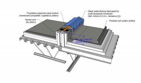
- The minimum height of an expansion joint may be reduced to 127 mm (5") if the primary roof membrane flashing is sealed to a self-supporting purpose-made elastomeric expansion joint system.
- Proprietary elastomeric expansion joint systems, provided by others and manufactured with an EPDM-based core and flanges that can be fully bonded to the primary membrane, are not covered by a RoofStar Guarantee (unless expressly accepted by the Guarantor and listed in Division C) but may be incorporated as part of the roof system provided the elastomeric expansion joint system is
- specified for installation on a divided, raised structure,
- compatible with the roof membrane and acceptable to the manufacturer,
- designed and manufactured to accommodate building movements of at least 500% elongation at -40°C (-40°F) across its length and at all vulcanized points,
- factory-fabricated by means of vulcanization,
- manufactured as one piece, complete with all joints, details, and connections, and
- completely protected from damage with sloped linear metal flashing.

10.1.6.2. Control Joints (Roof Dividers)
(See Note A-10.1.6.2.; also see Article 10.3.6.2.)
- The Design Authority is responsible
- to determine the need for control joints (roof dividers), and
- to specify their location and design.
- The Design Authority must consider specifying control joints
- when a single roof area exceed 61 m (approx. 200’) in length and the membrane is limited in its flexibility (consult the manufacturer for their recommendations),
- for buildings in climate zones with significant seasonal temperature swings,
- where an addition joins an existing building,
- where the deck type changes (i.e., steel transitions to wood),
- where insulation in the roof system changes thickness,
- where the roof deck changes in elevation, and
- when interior heating conditions change.
- Specified and detailed control joints should be located at the high points of the roof, so that water drains away from both sides of the divider and is not impeded by it.
- Control joints must be
- constructed as a raised divider,
- sloped on the top face (this may be bi-directional, or only toward one side) ,
- enveloped with no fewer than two plies of sheet membrane flashing ,
- at least 127 mm (5”) in height, measured from the finished system surface, when covered with a metal cap flashing (this minimum may be reduced to 101.4 mm (4”) when the metal cap flashing is omitted), and
- waterproofed in keeping the requirements in Article 10.3.2.3., together with the manufacturer’s published specifications for the detail.
- Unless otherwise approved by the Guarantor, control joints must be specified to divide a new roof system (addition) from existing roof systems (Ref. Article 1.1.4.5.).
10.1.7. Intersections with Other Roof Systems
(The requirements in Subsection 10.1.3., "All Systems", shall be read together with the following Articles)
10.1.7.1. Intersections with Water-shedding Roofs
- Intersections with water-shedding roofs must be designed according to the requirements in Article 10.3.7.2.
10.1.7.2. Intersections with Membrane Gutters
- Refer to Article 11.1.4.3.
10.1.8. Alternative Approaches for Membrane Flashing
(The requirements in Subsection 10.1.3., "All Systems", shall be read together with the following Articles)
10.1.8.1. Specifying Hazard-reduction Strategies
- The Design Authority should consider alternatives to heat-applied materials when the application process involves Hot Work (Ref. Article 1.1.3.5.) and the substrate to which they will be applied is combustible, or when nearby structures, openings, or materials, present a fire hazard; in the alternative, choose a suitable separation or overlay material as protection from open flame.
- Self-adhering or adhesive-applied membranes as alternatives to heat-applied membranes are acceptable to the Guarantor and must also be acceptable to the manufacturer.
- The application of materials to a combustible surface, using a torch, is strictly prohibited (Refer to Sub-section 10.3.8., "Alternative Approaches to Sheet Membrane Flashing", for application requirements).
Section 10.2. Materials
(See Division C, "Accepted Materials")
10.2.1. Material Properties
10.2.1.1. Flashing Membranes
- Sheet membranes used to flash the intersection of the roof field and perimeter walls must conform to the membrane requirements found in Article 9.2.1.1.
- When waterproofing a tall parapet above the primary membrane roof system is specified as part of the Contractor's scope of work (Ref. Article 10.1.4.3. and Article 10.3.4.3.), the membrane shall
- be compatible with the primary membrane,
- be self-adhering,
- be declared suitable for the application by the manufacturer (see Note A-10.2.1.1.(2)(3)),
- possess properties consistent with the design and characteristics of the wall assembly,
- possess a high softening point and a minimum flow temperature of 87.7°C (190°F) (ASTM D5147, "Standard Test Methods for Sampling and Testing Modified Bituminous Sheet Material") and
- have a thickness no less than 1 mm (.040”).
- Some membranes may be susceptible to damage from bird droppings, pet urine, and chemical contamination (oils, solvents, or any discharge from a mechanical unit), and therefore they should be protected using measures designed in consultation with the manufacturer.
- Fleece-reinforced liquid membrane flashing systems must be accepted by the Guarantor and proprietary to, or accepted by, the manufacturer.
10.2.1.2. Linear Metal Flashing
- Linear metal flashing incorporated into roof perimeters and walls must conform to the materials and fabrication requirements in Part 13, "Linear Metal Flashing".
10.2.1.3. Reserved
10.2.1.4. Sealants
- Sealants applied to linear metal flashing, where sheet membrane flashing is terminated, shall conform to the requirements in Article 13.2.1.4.
10.2.2. Securement Materials
10.2.2.1. Fasteners
- Where fasteners are used in the roof system
- to secure waterproofing materials, they shall conform to the requirements in Article 3.2.2.1.
- to secure linear metal flashings, they shall conform to the requirements in Article 13.2.1.4.
Section 10.3. Application
10.3.1. Guarantee Term Requirements
10.3.1.1. RoofStar 5-year Guarantee and RoofStar 10-year Guarantee
- To qualify for a RoofStar 5-year Guarantee or RoofStar 10-year Guarantee, all projects shall comply with the requirements in this Part.
10.3.1.2. RoofStar 15-Year Guarantee
- To qualify for a RoofStar 15-year Guarantee, all projects shall comply with the requirements in this Part for a RoofStar 5-year Guarantee or RoofStar 10-year Guarantee.
10.3.2. All Systems
10.3.2.1. Substrate Preparation
- All wall surfaces to which roofing materials must be installed (including Concrete Masonry Unit (CMU)) shall be
- prepared in like manner to the roof deck (Ref. Article 9.3.2.1.) and declared suitable by the manufacturer, or
- covered with a RoofStar-accepted overlay panel conforming to the material requirements in Article 5.2.1.3. and installed to conform to Article 5.3.2.5.
10.3.2.2. Material Preparation
- Membrane flashing shall be prepared following the manufacturer's published requirements.
10.3.2.3. General Application Requirements for Perimeters and Walls
- All changes in plane in the roof assembly must be waterproofed with a material acceptable to the Guarantor.
- Projects must follow proper sequencing so that materials, systems, or assemblies, installed by the Contractor correctly interface with materials, systems, or assemblies installed by other trades, to establish or preserve continuity and ensure positive waterproofing connections (overlapping, “shingle fashion”).
- When coordination with other trades requires some adaptation to the requirements in this Standard, any variance to proper detail sequencing must be approved in writing by the Design Authority.
- All sheet membrane flashing must
- satisfy the minimum requirements in Article 9.2.1.1.,
- be fully bonded to the field membrane and to an acceptable perimeter substrate,
- be installed to conform to the manufacturer's published instructions,
- be installed in strips the width of the membrane roll (the machine direction of the membrane must be oriented vertically); the exception to this may be membranes installed with hot bitumen (See Note A-10.3.2.3.(4)),
- be installed from the low point of the roof (for positive laps toward the drain),
- offset field membrane runs by at least 304.8 mm (12"),
- provide at least 203.2 mm (8") of two-ply coverage on a vertical surface, immediately above the finished system surface,
- be installed without fish-mouths or wrinkles,
- be hand-rolled with a manufacturer’s accepted roller and fully bonded to an acceptable, prepared substrate,
- be reinforced at all inside and outside corners with membrane gussets, measuring at least 101.6 mm x 152.4 mm (4” x 6”), excluding the tapered ends,
- wrap onto the outside face of a parapet or roof edge, and extend downward to overlap any cold joint by at least 50.8 mm (2”),
- overlap any wall membranes or finishes by at least 50.8 mm (2”), and shall
- underlap any wall membranes or finishes by at least 76.2 mm (3").
- Base sheet membrane flashing plies shall
- extend onto the field by at least 101.6 mm (4") or extend at least 101.6 mm (4") past perimeter mechanical fastener plates installed on the field,
- be fully bonded at the seams, along all exposed edges, and
- be finished and “buttered” before the end of the working day, with a torch or hot-air welder.
- Cap sheet membrane flashing plies must
- extend onto the field at least 152.4 mm (6"), or at least 50.8 mm (2”) past the edge of the base membrane flashing,
- be fully bonded at the seams, along all exposed edges, and
- exhibit continuous visible bitumen bleed-out along seam edges, to a maximum of 6.35 mm (1/4”), accomplished with a torch or hot-air welder.
- When sheet membrane flashing is carried up a vertical surface more than 606.9 mm (24"), and the membrane will be left exposed to the weather, the membrane shall be mechanically secured to the roof-side face of the wall at a reasonable interval between the roof field and the upper termination of the membrane.
- When mechanical securement of membrane flashing is required, it shall be fastened only on the vertical plane to minimize the possibility of leaks.
- Low-clearance openings in walls (rough openings less than 203.2 mm (8") in height, measured from the finished system surface) are permissible provided they conform to the requirements in Article 10.3.4.5.
- The upper termination of sheet membrane installed on the vertical plane must be protected from damage, and from water intrusion,
- with linear metal flashing installed in keeping with Article 13.3.2.1., "General Requirements for Linear Metal Flashing", or
- with a wall finish installed by others.
- When sheet membrane flashing is terminated on a vertical surface, it must be secured at its upper termination using
- Option 1 (Figure 10.3.2.3.-A), in which the upper edges of fully adhered sheet membrane flashing plies shall be protected and secured with overlapping adhered or self-adhered wall membranes and exterior sheathing,
- Option 2 (Figure 10.3.2.3.-B), where the upper edges of fully adhered sheet membrane flashing plies must be sealed, and mechanically secured to the wall substrate, with a RoofStar-accepted reinforced 2-component catalyzed polymethyl methacrylate (PMMA) liquid membrane flashing (Ref. Article 10.3.3.4., "Liquid Membrane Flashing"),
- Option 3 (Figure 10.3.2.3.-C), where
- the upper edges of fully adhered sheet membrane flashing plies shall be mechanically secured to the wall with a termination bar,
- an acceptable sealant shall be applied along the upper edge of the termination bar,
- the sealed termination bar shall be covered with a secondary linear metal counter-flashing installed in a cut reglet (groove), and
- an acceptable sealant shall be applied along the upper edge of the cut reglet flashing,
- Option 4 (Figure 10.3.2.3.-D), in which
- the upper edges of fully adhered sheet membrane flashing plies shall be mechanically secured to the wall with a termination bar or metal flashing,
- an acceptable sealant shall be applied along the upper edge of the termination bar or metal flashing,
- the sealed termination bar or flashing shall be covered with a secondary "surface reglet" flashing secured against the surface of the wall, and
- an acceptable sealant shall be applied along the upper receiving edge of the "surface reglet", or
- Option 5 (Figure 10.3.2.3.-E), in which
- the upper edges of fully adhered sheet membrane flashing plies shall be mechanically secured to the wall with a linear metal counter-flashing ("surface reglet"),
- an acceptable sealant shall be applied along the upper edge of the counter-flashing,
- the sealed counter-flashing shall be covered with a secondary "surface reglet" flashing secured against the surface of the wall, and
- an acceptable sealant shall be applied along the upper receiving edge of the "surface reglet".
- When sheet membrane turned up the vertical plane is mechanically secured with a termination bar or a metal flashing, fasteners must be spaced no more than 304.8 mm (12”) O.C.
- When a second metal flashing is installed to protect a termination bar or flashing used to secure the sheet membrane flashing, it may be fastened no more than 609.6 mm (24”) O.C., provided the linear metal flashing maintains continuous contact with the substrate.
- When closer fastener spacing is required by the manufacturer, the wall must be constructed or modified to facilitate solid fastener securement.
- Where a roof allows water to freely drain off the edge, and the roof adjoins a wall, a cricket or diverter should be installed at the roof edge to prevent water intrusion behind wall finishes.
- EIFS walls that must be cut to permit membrane replacement work must be restored with back-wrapped mesh, a base coat, and a finish coat, or with another method that is equal or superior.
Figure 10.3.2.3.-A
Membrane Termination on Wall
Option 1
Forming Part of
Clause 10.3.2.3.(11)(1)(1)
(Click to expand)Figure 10.3.2.3.-B
Membrane Termination on Wall
Option 2
Forming Part of
Clause 10.3.2.3.(11)(2)
(Click to expand)Figure 10.3.2.3.-C
Membrane Termination on Wall
Option 3
Forming Part of
Clause 10.3.2.3.(11)(3)
(Click to expand)Figure 10.3.2.3.-D
Membrane Termination on Wall
Option 4
Forming Part of
Clause 10.3.2.3.(11)(4)
(Click to expand)Figure 10.3.2.3.-E
Membrane Termination on Wall
Option 5
Forming Part of
Clause 10.3.2.3.(11)(5)
(Click to expand)


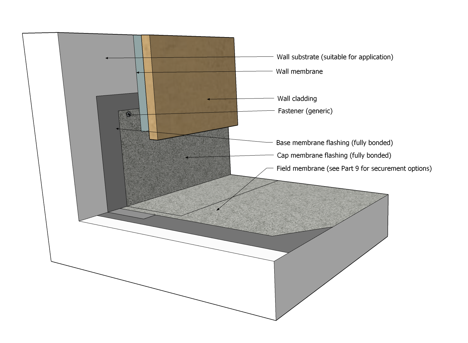
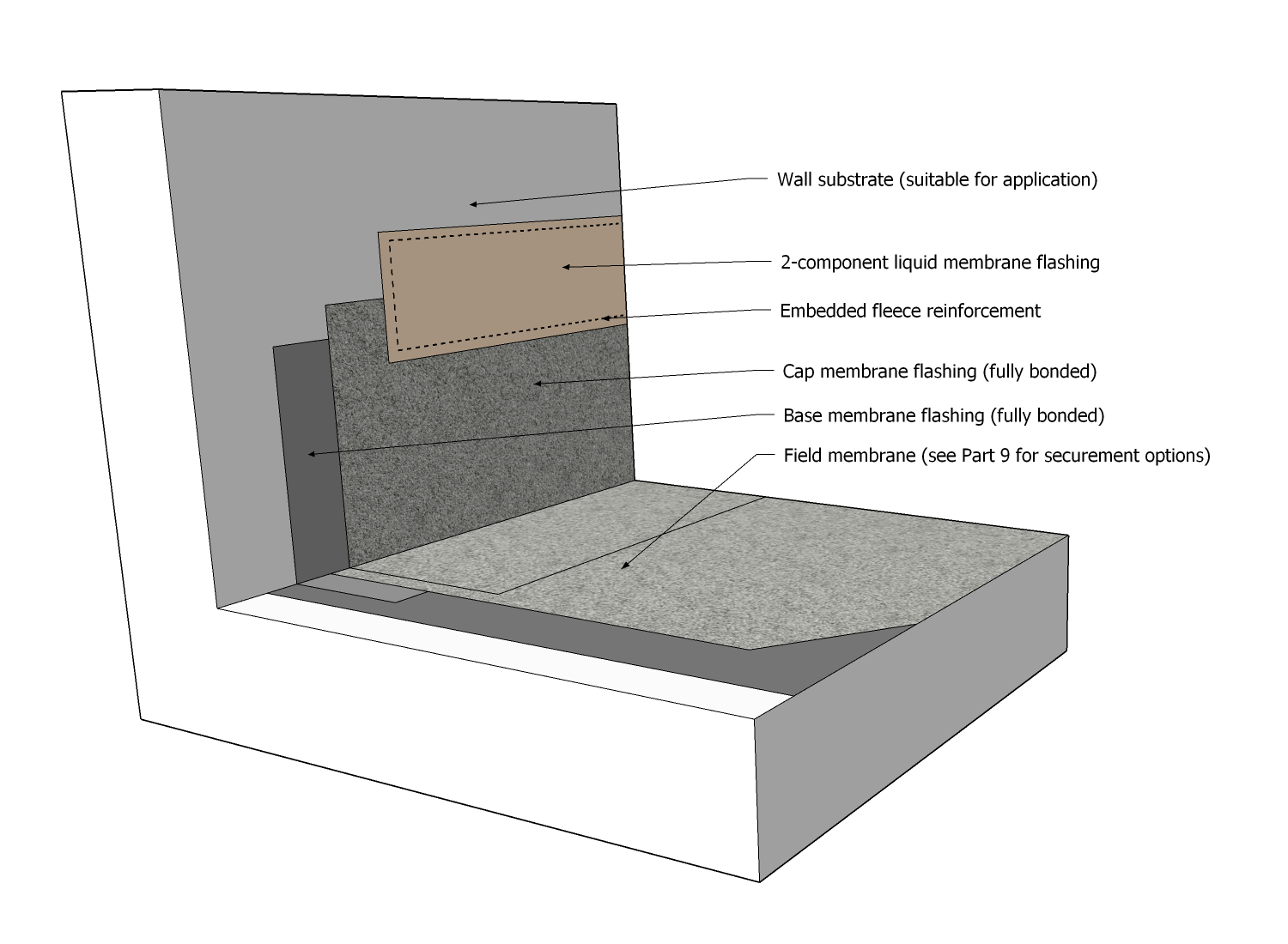
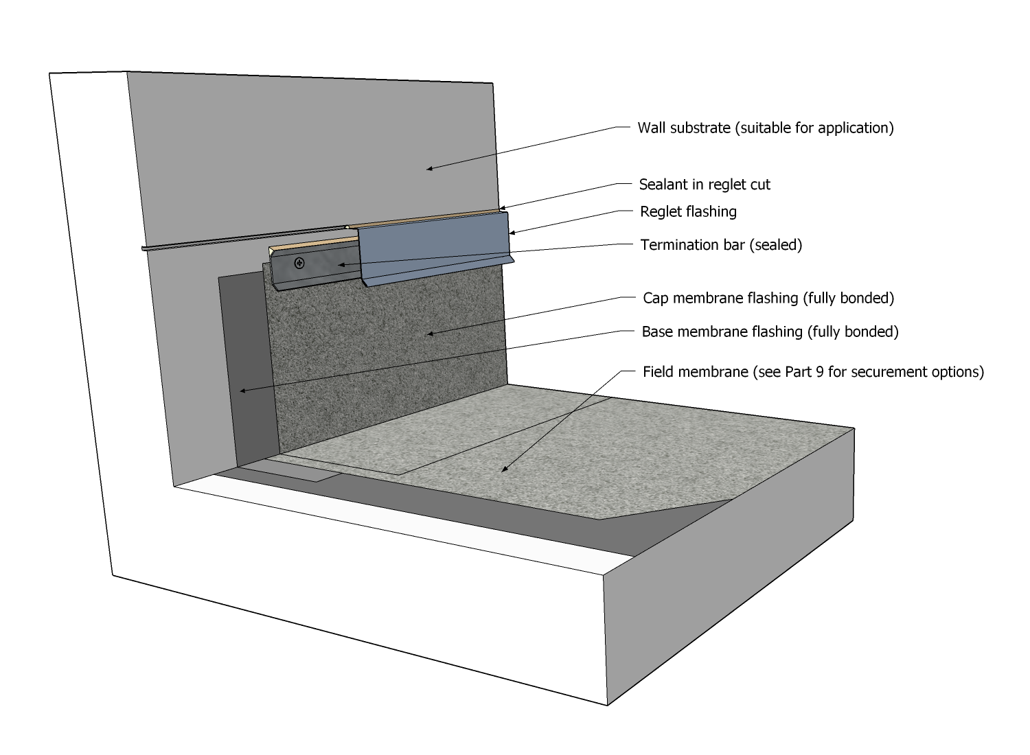
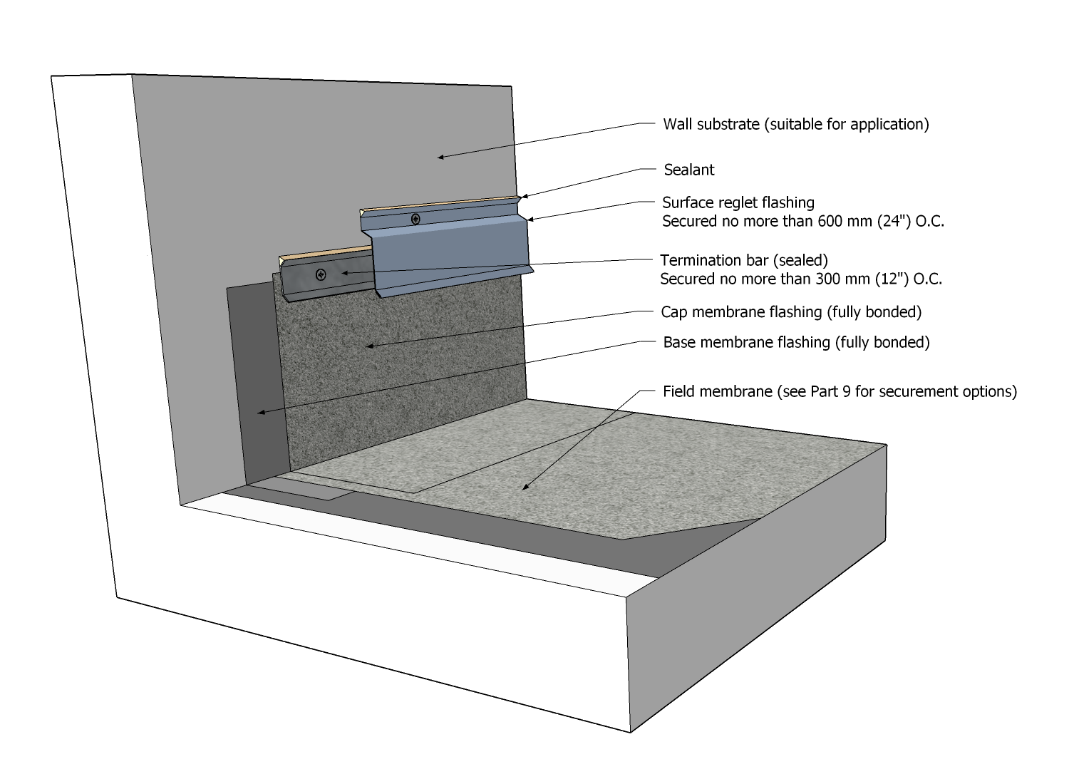
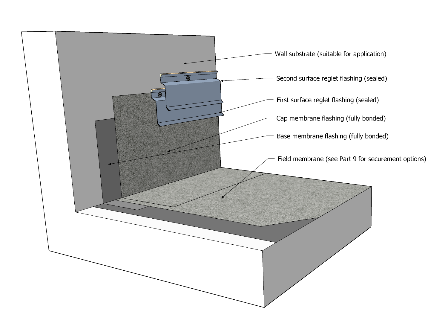
10.3.2.4. Protection of Membranes
- All installed membranes must be protected from splashed or dripped primer (applicable to all trades).
- Membrane flashing must be protected from damage caused by UV radiation, foot traffic, or shifting coverings, using a linear metal flashing (i.e., base flashing) or other methods acceptable to the Guarantor.
- Protection materials shall be installed as required in Article 9.3.2.7.
- When an integrity scan is not required because the conditions in Article 1.1.3.3. have been satisfied, the Contractor shall nevertheless protect installed field membranes and membrane flashing, immediately after installation, with RoofStar-accepted membrane protection materials.
10.3.3. Additional Requirements for Membrane Flashing
(The requirements in Subsection 10.3.2., "All Systems", shall be read together with the following Articles)
10.3.3.1. Torch-applied Membranes
- The application of an open flame to combustible surfaces is not permitted.
- All combustible surfaces, including (without limitation) decks, walls, blocking, or canted edges, must be protected from open flame by an acceptable separation or overlay material.
- When the base membrane flashing is torch-applied, all overlay board joints and wall transitions must be sealed with the primary membrane manufacturer’s approved self-adhered membrane or tapes, or follow the methodologies in Sub-section 10.3.8., "Alternative Approaches to Sheet Membrane Flashing".
10.3.3.2. Self-adhered and Cold Processed Membranes
- Self-adhered membranes must be installed on a clean, uncontaminated surface.
- All self-adhered and cold processed sheet membrane flashing that terminates on the vertical plane must be mechanically secured.
- When self-adhered or cold-processed base sheet membrane flashing overlaps granule-surfaced cap sheet membrane flashing, the overlap shall be no less than 76.2 mm (3"), granules on the cap sheet membrane must be embedded to expose bitumen, and the overlap must be continuously sealed to comply with the requirements in Article 9.3.3.1.
10.3.3.3. Adhesive-applied and Hot Asphalt-applied Membranes
- Self-adhered membranes must be installed on a clean, uncontaminated surface.
- Hot asphalt-applied sheet membrane installed on a vertical plane must conform to the manufacturer's installation specifications, using the manufacturer's accepted Type 3 or 4 oxidized asphalt or Type 3 or 4 SEBS modified asphalt.
- Asphalt temperature must conform to the membrane manufacturer's minimum application temperature; a minimum application temperature of 205°C (400°F) is required.
- When hot asphalt is used to adhere membrane flashing (stripping), metal base flashing is required on all vertical surfaces, walls, curbs, etc. (also see Article 13.3.2.3., "Cap Flashing, Counter-flashing, and Reglet Flashing")
10.3.3.4. Liquid Membrane Flashing
- Two-component fleece-reinforced catalyzed polymethyl methacrylate (PMMA) liquid membrane flashing systems must be accepted by the Guarantor and listed in Division C, and
- may be used
- on the drainage plane,
- where sheet membrane flashing may not be practical or even possible,
- to terminate the top edge of sheet membrane flashing,
- for sheet membrane reinforcement (i.e., at corners),
- where abrasion resistance is desirable,
- where resistance to sheet membrane contamination is necessary, or
- where the Design Authority specifies its application.
- must be compatible with the primary sheet membrane flashing.
- may be used
- For all applications,
- the substrate must be clean, dry, free of contaminants, and primed, as directed by the flashing system manufacturer,
- a base layer of catalyzed liquid membrane resin must be applied within the area masked for coverage,
- the base coating must be reinforced with the manufacturer’s fleece, cut to size so that the fleece is set in from the masked area no more than 3.18 mm (1/8”),
- the fleece must be fully saturated with liquid, following the published instructions from the manufacturer, and
- the embedded fleece must be coated with a second application of catalyzed liquid membrane resin, covering the masked area.
- On vertical sheet membrane terminations, the liquid membrane flashing system shall provide no less than 50.8 mm (2") coverage, both above and below the sheet membrane termination.
- Application rates and guidelines issued by the manufacturer of the liquid flashing product must be followed, unless superseded by these requirements (Ref. Figure 12.3.2.6.-A).
- Where a fleece-reinforced 2-component catalyzed polymethyl methacrylate (PMMA) or polyurethane methyl methacrylate (PUMA) liquid membrane flashing system serves as a substitute for sheet membrane flashing, the reinforced liquid membrane flashing system must extend at least 203.2 mm (8”) up the vertical plane, and no less than 203.2 mm (8") onto the horizontal field plane.
- When a granule surface or textured finish is specified, the granules or texturing material must be broadcast into a third coat.
10.3.4. Perimeter Details, High Walls, and Openings
(The requirements in Subsection 10.3.2., "All Systems", shall be read together with the following Articles)
10.3.4.1. Parapets
(See Figures 10.3.4.1.-C through 10.3.4.1.-K, below. Also refer to Construction Details (Division D), Parapet (Typical))
- All standard parapets (609.6 mm (24”) or less in height)
- must be completely waterproofed with membrane flashing conforming to the minimum requirements in Article 9.2.1.1. and installed to conform to Article 10.3.2.3., and
- shall be waterproofed
- with sheet membrane oriented vertically on the inside surface,
- on the roof-side (inside) surface with two plies of membrane that terminate on the roof field as required in Article 10.3.2.3., and
- on the top and outside surface with at least one ply of membrane.
- Membrane flashing applied to parapet walls must be fully bonded to the entire surface of the parapet (Ref. Article 13.3.2.3.(4)).
- Coping that is part of the roof system must be continuously waterproofed as part of the roof system, even if the coping is flashed separately from the parapet wall.
- All membrane flashing bonded to a parapet coping shall continue over the top and extend down the outside face of the coping, overlapping any joint at least 50.8 mm (2”).
Figure 10.3.4.1.-A Parapet Membrane Details
Forming Part of Article 10.3.4.1.
(Click to open related Construction Detail)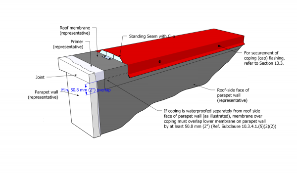
Figure 10.3.4.1.-B Parapet Membrane Details
Forming Part of Article 10.3.4.1.
(Click to open related Construction Detail)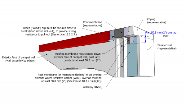
- Notwithstanding Sentence (1), a standard parapet may be flashed with base sheet membrane using the alternate method described below, but this method is permissible only if allowed in writing by the manufacturer, and only if installed as follows:
- Base sheet flashing plies shall be installed on the inside surface of the parapet as required in Sentence (1) and shall terminate at the top inside edge, where each ply must be mechanically secured (see Construction Detail “SBS | Typical”).
- Membrane applied across the top of the parapet may be oriented with the “machine direction” parallel to the long axis of the parapet, but the membrane
- must be a base membrane satisfying the minimum requirements in Article 9.2.1.1. and shall be compatible with all other membranes installed on the parapet,
- shall overlap the vertical plies of base sheet membrane flashing at least 50.8 mm (2”), and
- shall overlap the outside surface of the parapet, and any joints between the coping and the wall, as required in Article 10.3.2.3.
- Regardless of parapet height, no fewer than two plies of sheet membrane flashing shall be carried up the inside face of the parapet at least 203.2 mm (8") above the finished system surface.
- A tall parapet (taller than 609.6 mm (24”) nominal) shall be waterproofed in keeping with the requirements in Article 10.3.4.3.
- Where a parapet intersects with a higher wall, water must be directed away from the union and onto the roof surface (See Figures 10.3.4.1.-C through 10.3.4.1.-K, below) by flashing the union with
- an acceptable SBS-modified bituminous sheet membrane flashing,
- membrane gussets at the corners, and
- a metal saddle assembly.
- When a parapet is capped with a pre-cast concrete or stone coping,
- the membrane over the top of the parapet must be drilled by others to receive dowels,
- the dowels must be installed by others, and
- the dowels must be sealed by the Contractor, following the requirements in Article 14.3.2.7., Sentences 6 and 7, for sealing dowels installed in pre-curbs.


Figure 10.3.4.1.-C
Parapet-Wall Intersection
Step 1
Forming Part of
Sentence 10.3.4.1.(8)
(Click to expand)Figure 10.3.4.1.-D
Parapet-Wall Intersection
Step 2
Forming Part of
Sentence 10.3.4.1.(8)
(Click to expand)Figure 10.3.4.1.-E
Parapet-Wall Intersection
Step 3
Forming Part of
Sentence 10.3.4.1.(8)
(Click to expand)
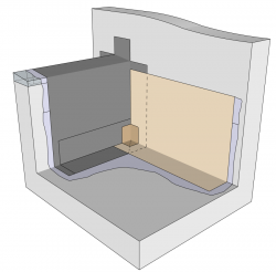
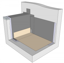
Figure 10.3.4.1.-F
Parapet-Wall Intersection
Step 4
Forming Part of
Sentence 10.3.4.1.(8)
(Click to expand)Figure 10.3.4.1.-G
Parapet-Wall Intersection
Step 5
Forming Part of
Sentence 10.3.4.1.(8)
(Click to expand)Figure 10.3.4.1.-H
Parapet-Wall Intersection
Step 6
Forming Part of
Sentence 10.3.4.1.(8)
(Click to expand)
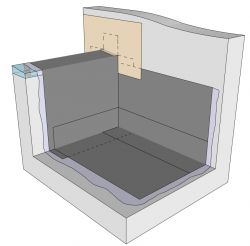
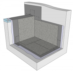
Figure 10.3.4.1.-I
Parapet-Wall Intersection
Step 7
Forming Part of
Sentence 10.3.4.1.(8)
(Click to expand)Figure 10.3.4.1.-J
Parapet-Wall Intersection
Step 8
Forming Part of
Sentence 10.3.4.1.(8)
(Click to expand)Figure 10.3.4.1.-K
Parapet-Wall Intersection
Step 9
Forming Part of
Sentence 10.3.4.1.(8)
(Click to expand)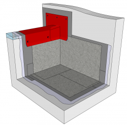
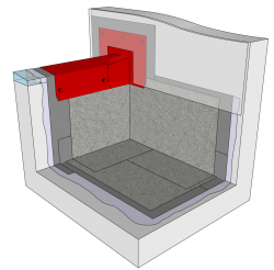
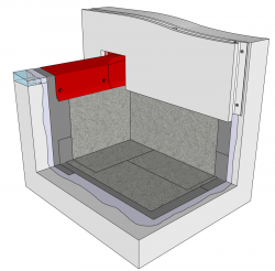
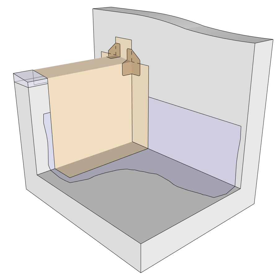
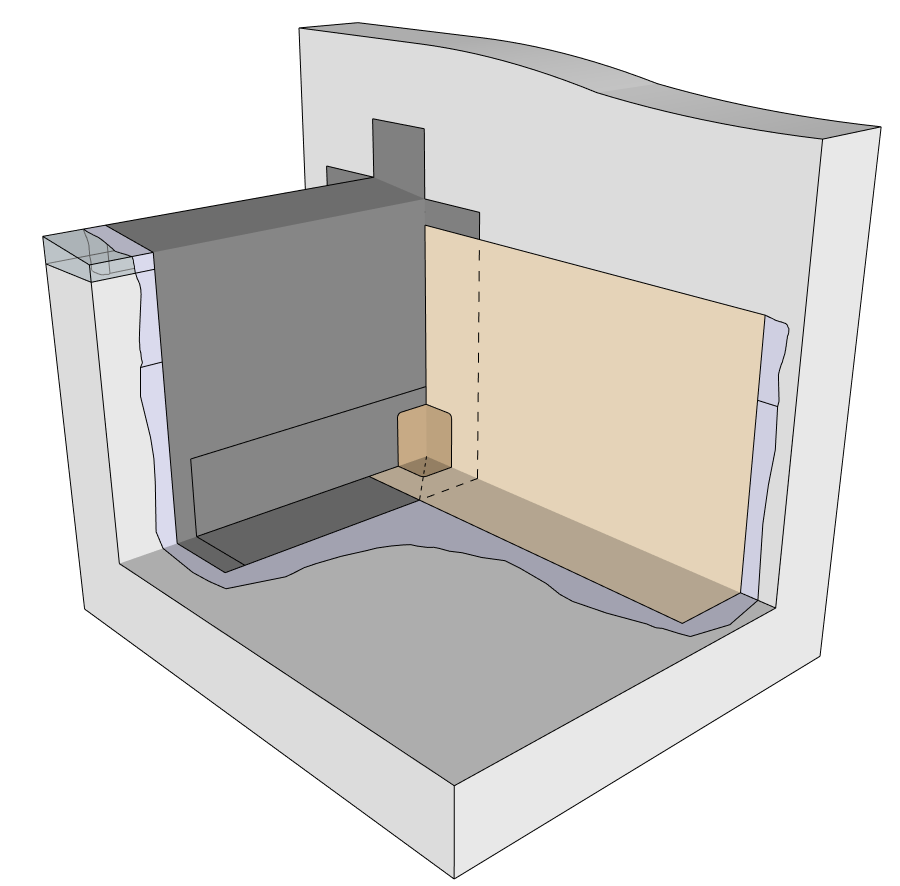

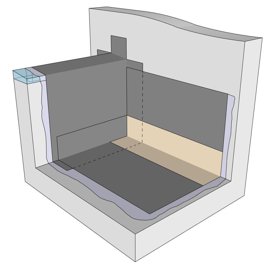
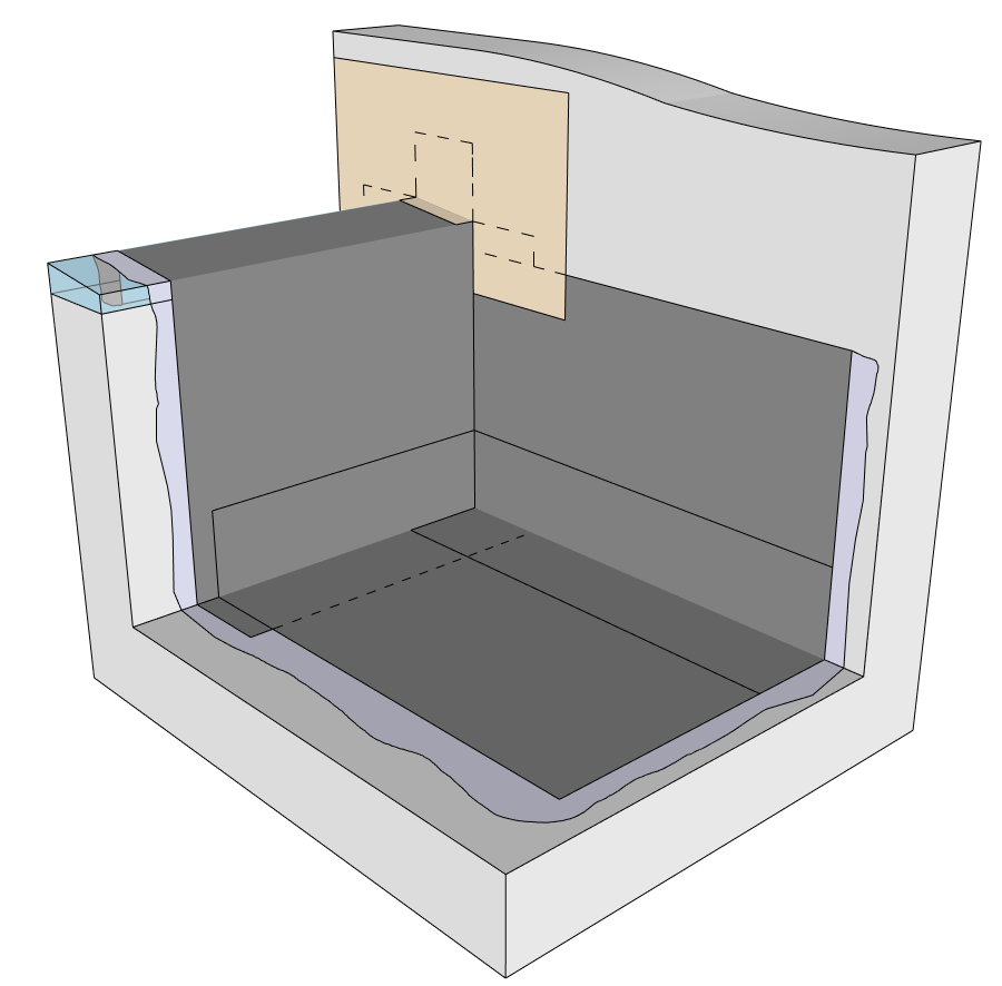


10.3.4.2. Low Profile Edges
- Metal edge flashings must be
- supported over a solid substrate,
- installed after application of the base field membrane, which must wrap onto the outside face of the roof edge and extend downward to overlap any cold joint by at least 50.8 mm (2”),
- embedded in a membrane-compatible mastic or sealant,
- fastened to the roof structure with mechanical fasteners spaced 203.2 mm (8”) O.C. in offsetting rows, (Ref. Article 13.3.2.1.),
- joined to each other with lap joints measuring at least 101.6 mm (4”), each joint sealed with butyl or gunnable sealant,
- cleaned and prepared to receive membrane,
- primed with the manufacturer's accepted primer, unless specified otherwise by the manufacturer,
- sealed to the base membrane, which must extend
- at least 101.6 mm (4") onto the metal flashing, and at least 50.8 mm (2”) past the fasteners, and
- at least 101.6 mm (4”) onto the field membrane, and
- finished with the field cap membrane
- which must extend to cover the base membrane, and
- which must be sealed along the exposed edge with an un-tooled bead of membrane-compatible mastic.
- Existing and new canted edges must be
- made of wood, and
- flashed with sheet membrane in keeping with the requirements in Article 10.3.2.3.
10.3.4.3. Tall Parapets
( See Figure 10.3.4.3.-A)
- Sheet membranes installed on a tall parapet, above the termination of primary roof membrane flashing,
- shall conform to the material requirements in Article 10.2.1.1.,
- must be applied with the methodology prescribed by the manufacturer,
- shall positively overlap the primary sheet membrane flashing by at least 50.8 mm (2”),
- shall underlap sheet membrane flashing installed to cover the top of a parapet by at least 50.8 mm (2"),
- may be used to waterproof the coping of a tall parapet, and
- shall be protected from UV radiation with a metal flashing, cladding or another wall covering.
- The application of membrane over the coping of a tall parapet shall conform to the manufacturer’s prescribed methodologies but may be installed parallel to the long axis of the parapet as permitted in Article 10.3.4.1.(2) for a standard parapet, provided the conditions therein are satisfied.
Figure 10.3.4.3.-A Membrane Application on Tall Parapet
Forming Part of Sentence 10.3.4.3.(1)
(Click to expand illustration)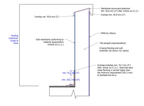
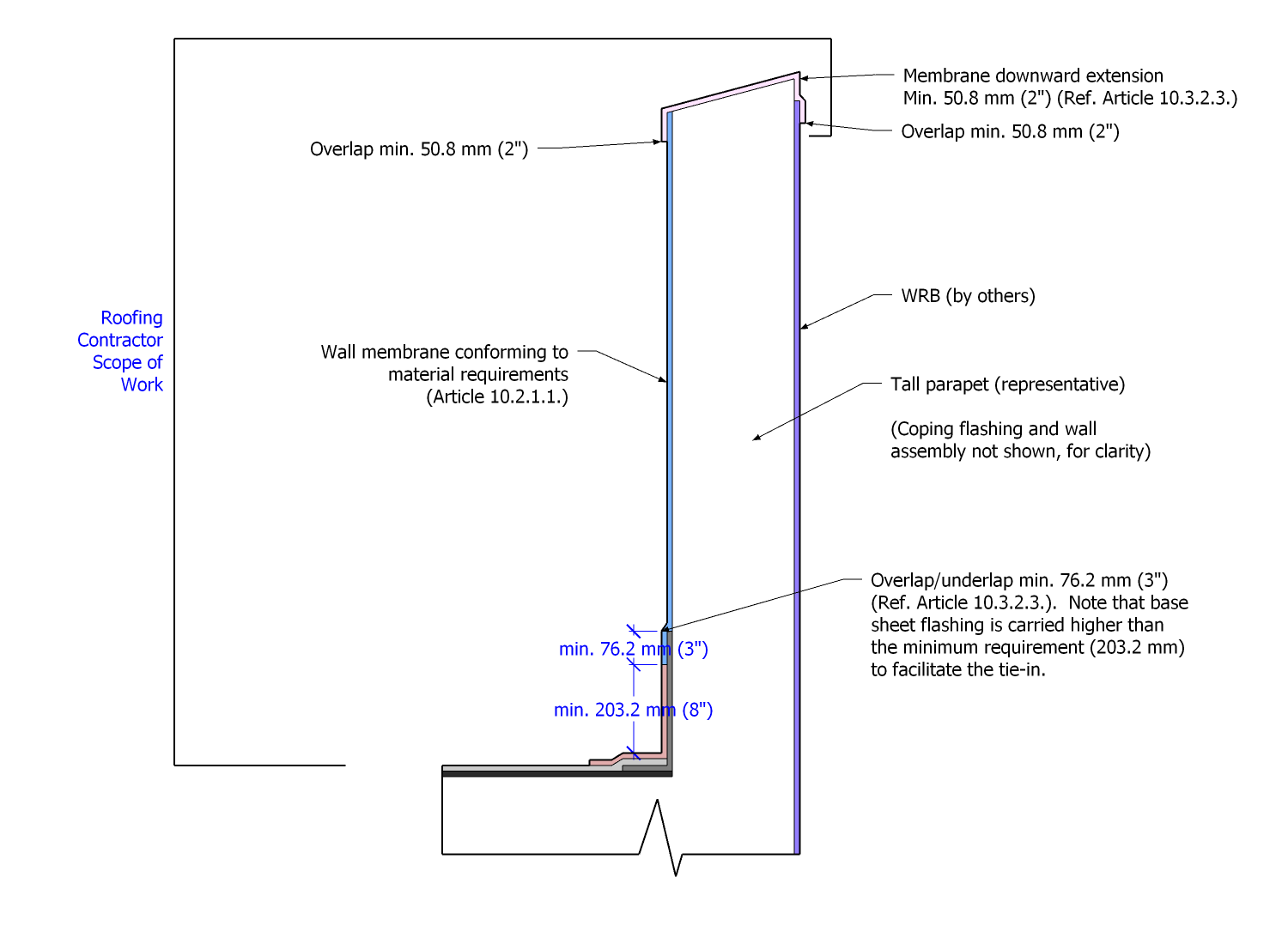
10.3.4.4. Fire Separations
(For reference, see Construction Detail "SBS | Fire Separation Joint" and "SBS | Fire Separation Wall")
- Fire separation walls and joints
- shall conform to the specified design,
- shall be waterproofed in keeping with the requirements in this Part,
- shall not incorporate combustible materials over the top of the joint or wall,
- shall be offset from metal cap flashing joints (in the alternative, soldered standing seams or a water channel clip may be used when joints align; see Construction Detail "SBS | Fire Separation Wall"),
- shall exclusively utilize s-locks and concealed continuous clips for securing linear metal flashing to a firewall face, and
- shall utilize only standing seam joints for linear metal cap flashings.
10.3.4.5. Doors, Windows, and Wall Openings
(See Figure 10.3.4.5.-A)
- Rough openings formed or framed in walls to accommodate doors, windows, curtain-wall assemblies, or other penetrations (i.e., ventilation grilles), must be waterproofed before the door, window, curtain-wall, or another assembly is installed.
- All rough openings must be suitable for the application of sheet membrane flashing or reinforced liquid membrane flashing systems, and any work to render surfaces suitable shall be performed by others.
- Low-clearance openings (rough openings less than 203.2 mm (8") in height, measured from the finished system surface) must be flashed using methods described in this Article; curtain-wall openings may be flashed using a modified metal water-stop flashing method by eliminating the metal water-stop flashing, provided the remaining required work is executed by the Contractor.
- Membranes used for this application must conform to the material requirements in Article 10.2.1.1., "Flashing Membranes".
- In all methods described in this Article, low-clearance openings must be pre-flashed with no less than one ply of base sheet membrane
- lapped over the field membrane in keeping with requirements found elsewhere in this Part,
- carried over the top face of the rough opening, and
- carried vertically above the sill, at least 101.6 mm (4").
- Regardless of the method described below, the membrane installed over the rough opening sill must be protected from abrasion damage with
- a full-coverage pre-manufactured threshold step (by others),
- a full-coverage metal flashing, supplied and installed by the Contractor, or
- fleece-reinforced PMMA, coated with an abrasion-resistant coating proprietary to the PMMA manufacturer.
- When the metal water-stop flashing method is specified,
- all corners must be reinforced with compatible membrane gussets, and.
- the metal water-stop flashing must be
- fabricated to fit the full width of the opening,
- fashioned with a water dam upstand measuring at least 25.4 mm (1”) in height,
- installed over the sill membrane,
- embedded in a membrane-compatible mastic or sealant,
- mechanically attached to the sill, and
- sealed to the rough opening with an additional ply of membrane flashing.
- When the metal sill-pan flashing method is specified, a single-piece metal pan sill flashing must be
- fabricated to fit snugly inside the rough opening,
- folded, welded, or soldered in the corners,
- fashioned with a water dam upstand measuring at least 25.4 mm (1”) in height,
- fabricated with 101.6 mm (4”) high flanges that cover the insides of the rough opening and wrap around the outside face of the wall at least 101.6 mm (4”),
- installed over the pre-flashing membrane and embedded in a membrane-compatible mastic or sealant,
- mechanically attached to both the outside and inside faces of the rough door opening, and
- sealed to the rough opening with an additional ply or coating of membrane flashing.
- When clearances preclude the use of either the metal water-stop flashing method or the metal sill-pan flashing method, the rough opening may be flashed using reinforced liquid membrane flashing.
- When a reinforced liquid membrane flashing method is specified,
- the rough opening must be flashed using the metal water-stop method,
- the metal water-stop flashing must be sealed to the pre-flashing base membrane using an accepted liquid membrane flashing system,
- the inside faces of the rough opening must be flashed with reinforced liquid membrane flashing, ensuring an overlap with the membrane on the sill at least 50.8 mm (2”),
- liquid membrane flashing must extend up the inside faces of the rough opening at least 101.6 mm (4”), and
- the liquid membrane flashing system must be applied following the requirements in Article 10.3.3.4.
- Overflow drains must
- be installed on the roof area adjacent any rough low-clearance opening,
- be located at least 25.4 mm (1") below a rough low-clearance opening, and
- conform to the spacing and capacities required by the "National Plumbing Code of Canada", Division B, Article 2.4.10.4. (See also Article 11.1.3.1., "Principles of Design").
Figure 10.3.4.5.-A Low Door Opening
Forming Part of Article 10.3.4.5.
(Click to open related Construction Detail)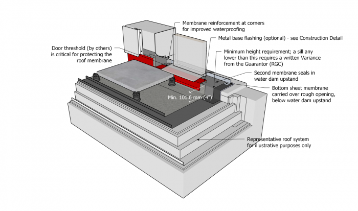
10.3.5. Reserved
10.3.6. Expansion and Control Joints
(The requirements in Subsection 10.3.2., "All Systems", shall be read together with the following Articles)
10.3.6.1. Expansion Joints
- Expansion joints, which are framed and sheathed by others, must be
- sloped toward the roof surface on the top face of each side,
- waterproofed as shown in Construction Detail "Expansion Joint (Field)", with methods and materials conforming to the requirements in Article 9.3.2.3., and with the manufacturer’s published specifications for the detail, and
- covered with 2-part linear metal flashings (counter-flashing and cap flashing) that permit multi-directional movement in the joint.
- When proprietary elastomeric expansion joint systems are specified, the bond between the sheet membrane flashing and the expansion joint system must be acceptable to both the manufacturer and the supplier of the expansion joint system (Ref. Article 10.1.6.1. for design requirements).
- Field splicing of proprietary elastomeric expansion joints is permissible only when made with a machine acceptable to the expansion joint manufacturer.
10.3.6.2. Control Joints (Roof Dividers)
- Control joints must be waterproofed in keeping the requirements in Article 10.3.2.3., together with the manufacturer’s published specifications for the detail.
10.3.7. Intersections with Other Roof Systems
(The requirements in Subsection 10.3.2., "All Systems", shall be read together with the following Articles)
10.3.7.1. Compatibility of Materials
- Where two roof systems intersect, materials must be compatible with each other, or must be separated from contact by an intermediate separation layer.
10.3.7.2. Intersections with Water-Shedding Roofs
(See Note A-10.3.7.2.)
- When a waterproofing roof system transitions down a slope onto a lower water-shedding roof system, the waterproofing membrane must lap over the water-shedding roof system by no less than 50.8 mm (2").
- When a waterproofing roof system transitions up a slope and underlaps a water-shedding roof system,
- sheet membrane flashing must extend up the water-shedding roof system slope at least
- 152.4 mm (6”), plus at least 76.2 mm (3”) for the overlap by the water-shedding roof system, when measured vertically from the maximum water level, and
- 304.8 mm (12”) plus at least 76.2 mm (3”) for the overlap by the water-shedding roof system, when measured vertically from the maximum water level, in regions with typical heavy snow,
- the termination of the waterproofing roof system sheet membrane flashing on the slope must be mechanically secured, separately from the water-shedding roof system, and
- the overlapping of adjoining roof system materials must conform to the requirements for the specific water-shedding roof system.
- sheet membrane flashing must extend up the water-shedding roof system slope at least
10.3.7.3. Intersections with Membrane Gutters
- Refer to the requirements in Article 11.3.3.8.
10.3.8. Alternative Approaches to Sheet Membrane Flashing
(The requirements in Subsection 10.3.2., "All Systems", shall be read together with the following Articles)
10.3.8.1. General
- When field membranes or flashing plies are heat-welded, or when construction sequencing requires strategies for mitigating fire risk, the Contractor is responsible to assess risks and should consider the means and methods in Article 10.3.8.2. and Article 10.3.8.3.
10.3.8.2. Pre-flashing
- Before installing the base field membrane, self-adhering or adhesive-applied base membrane flashing (“pre-flashing”) must be applied to both vertical surfaces and to a suitable substrate on the roof field (Figure 10.3.8.2.-A).
- Base membrane flashings must be finished and “buttered” at the joints using a hot-air welder, and must extend
- no less than 101.6 mm (4”) onto the roof field,
- the full height of a parapet less than 606.9 mm (24") in height, and
- no less than 203.2 mm (8”) on all other vertical surfaces.
- The ends of field membrane runs that are applied after base membrane flashing must continue up the face of the wall or parapet at least 101.6 mm (4”) (Figure 10.3.8.2.-B).
- Additional base membrane flashing must be installed along the lengths of base field membranes, applied to the vertical surface and onto the roof field at least 101.6 mm (4”) (Figure 10.3.8.2.-C).
- Cap field and flashing membranes must be installed in keeping with General Application standards (Figure 10.3.8.2.-D).
Figure 10.3.8.2.-A
Membrane Pre-Flashing
Step 1
Forming Part of
Sentence 10.3.8.2.(1)
(Click to expand)Figure 10.3.8.2.-B
Membrane Pre-Flashing
Step 2
Forming Part of
Sentence 10.3.8.2.(3)
(Click to expand)Figure 10.3.2.3.-C
Membrane Pre-Flashing
Step 3
Forming Part of
Sentence 10.3.8.2.(4)
(Click to expand)Figure 10.3.2.3.-D
Membrane Pre-Flashing
Step 4
Forming Part of
Sentence 10.3.8.2.(5)
(Click to expand)


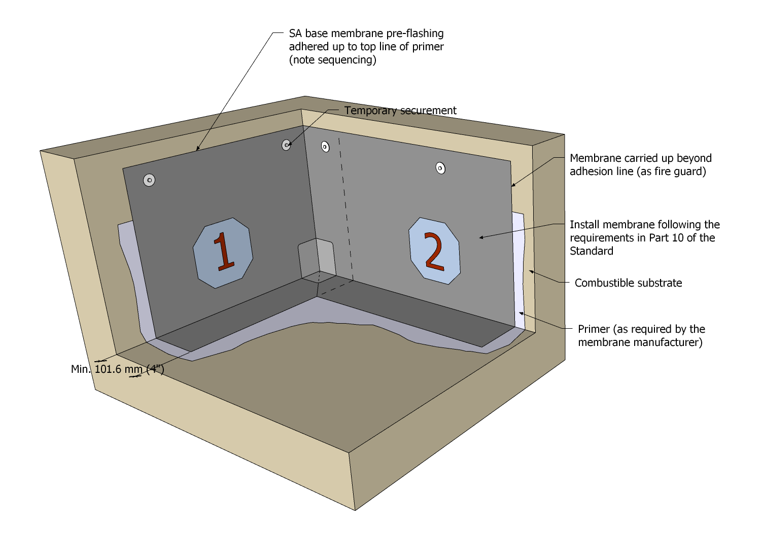
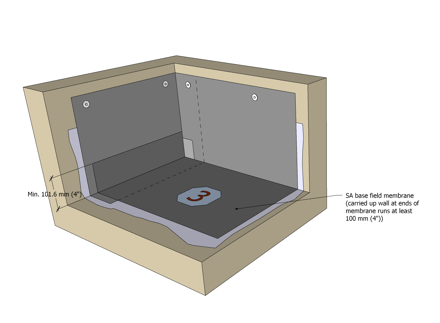
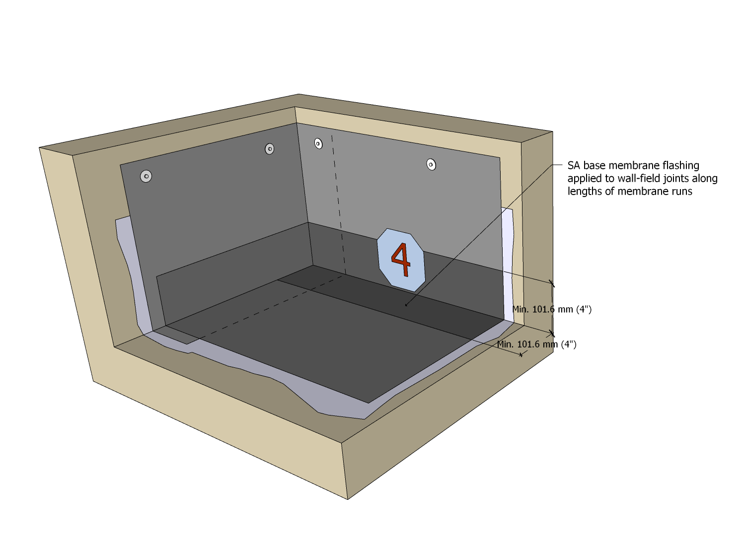
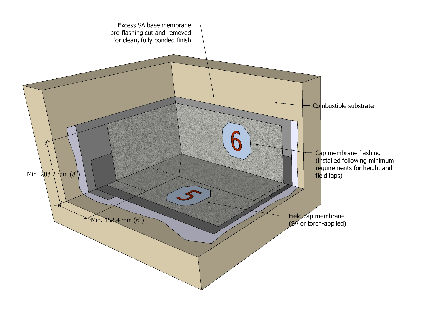
10.3.8.3. Picture-framing
- Before installing the base field membrane, the Contractor must “picture-frame” the field area adjacent sensitive perimeters (walls, curbs, or other details), using self-adhering or adhesive-applied membranes applied to a suitable substrate on the roof field.
- Picture-framing must be at least 1.5 m (58 ½”) wide, beginning with a half-width sheet installed along the sensitive perimeter (Figure 10.3.8..3.-A).
- Perimeters must be flashed with self-adhering or adhesive-applied membrane base flashing; base membrane flashing plies must extend
- no less than 101.6 mm (4”) onto the roof field,
- the full height of a parapet less than 606.9 mm (24") in height, and
- no less than 203.2 mm (8”) on all other vertical surfaces.
- Field base membrane runs must be installed and tied into the “picture frame” following the requirements in this Standard for side and end laps (Ref. Article 9.3.2.3.).
- Standard application of cap field membrane runs must be carried no closer than 1 m (39”) of the wall or parapet (Figure 10.3.8.3.-B).
- Self-adhering or adhesive-applied cap membranes must be applied to complete the field; side and end laps must be heat-sealed with a hot-air welder.
- Self-adhered or adhesive-applied cap membrane flashing must be applied to parapets or walls, in keeping with requirements in this Part for membrane flashing, and side and end laps shall be heat-sealed with a hot-air welder.
- All other applicable requirements in this Standard remain unaltered by this methodology.
Figure 10.3.8.3.-A
Membrane Picture-Framing
Base Membrane Stage
Forming Part of
Sentence 10.3.8.3.(2)
(Click to expand)Figure 10.3.8.3.-B
Membrane Picture-Framing
Cap Membrane Stage
Forming Part of
Sentence 10.3.8.3.(5)
(Click to expand)
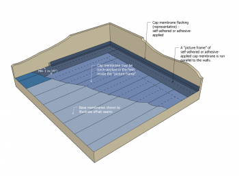
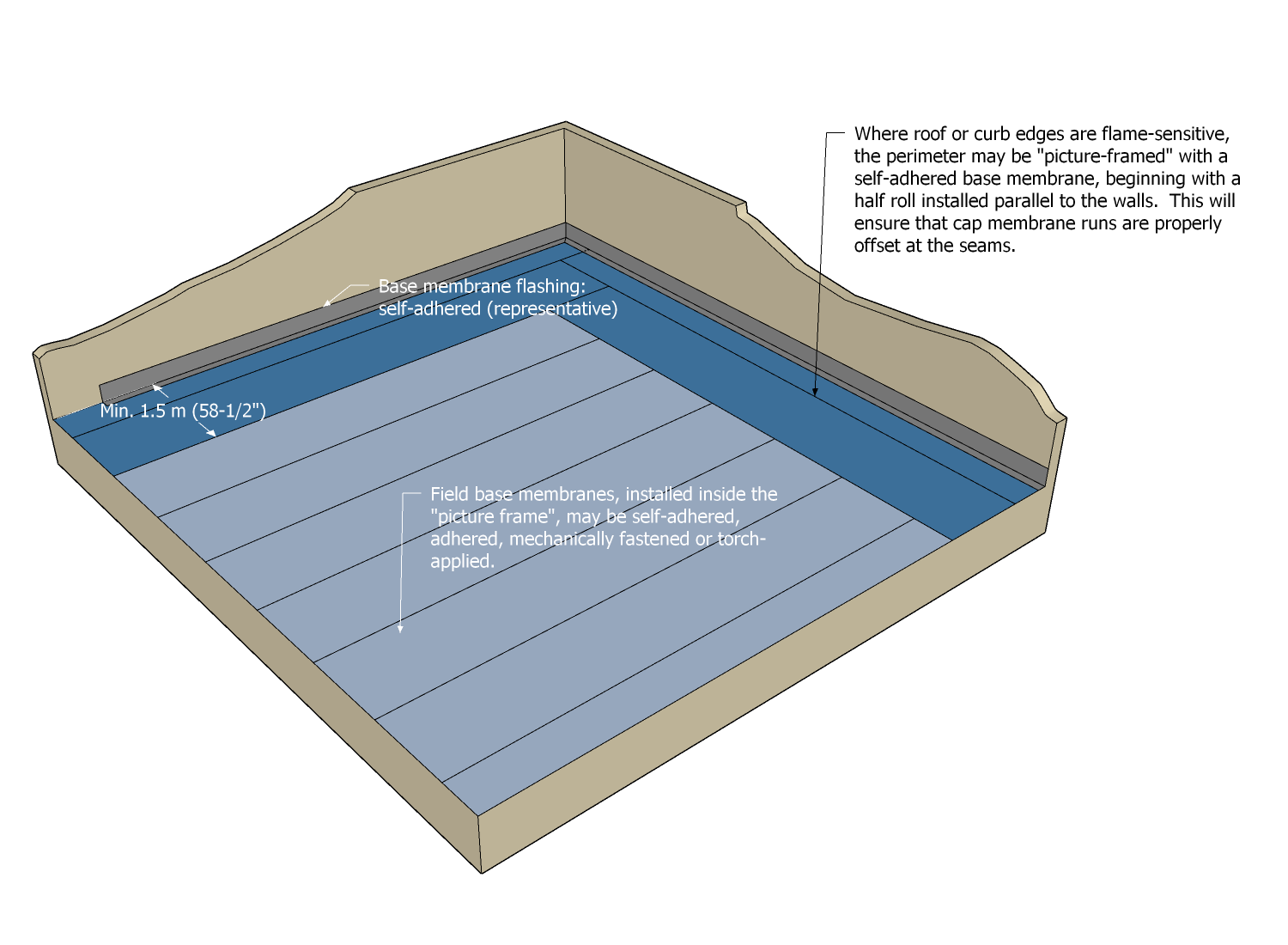

Part 11 - Drainage
Section 11.1. Design
11.1.1. General
11.1.1.1. Scope
- The scope of this Part and the Standard shall be as described in Division A, Part 1.
11.1.1.2. Defined Terms
- Words that appear in italics are defined in the Glossary. Additionally, the following terms are used in this Part:
- Bi-Level Drain means a drain with two inlets, each at a different elevation; these drains are typically used on roofs supporting overburden and are not to be used as an overflow.
- Drain leader means "a pipe that is installed to carry storm water from a roof to a storm building drain or sewer or other place of disposal” ("British Columbia Plumbing Code", Division A, Article 1.4.1.2., "Defined Terms").
- Flanged insert drain means a primary roof drain
- with a flat, broad flange that encircles, and is manufactured from the same material as, the drain opening or bowl,
- that is spun or hot-welded (not cast),
- that typically is secured to the roof assembly with screw-type mechanical fasteners, and
- that is manufactured with a short length of drain pipe ("drain stem"), which is inserted into a drain leader and sealed against back-flow using a compression seal.
- Overflow drain ("overflow") means a secondary roof drain
- that serves as a safeguard when roof drains fail, and
- which may be located in the roof field (for example, as a secondary drain) or at the perimeter of the roof.
- Primary roof drain means the primary means of draining water from the roof.
- Roof drain means “A fitting or device that is installed in the roof to permit storm water to discharge into a leader.” ("British Columbia Plumbing Code", Division A, Article 1.4.1.2., "Defined Terms").
- Scupper drain ("Scupper") means an open or closed roof drain that conveys water laterally from one roof area to another, or from the roof directly to the exterior of the building.
- Secondary roof drain means a drain connected to a separate drainage system, typically situated at a higher elevation than a primary roof drain. An overflow drain is a type of secondary roof drain.
11.1.2. Guarantee Term Requirements
11.1.2.1. RoofStar 5-year Guarantee and RoofStar 10-year Guarantee
- To qualify for a RoofStar 5-year Guarantee or RoofStar 10-year Guarantee, all projects shall comply with the requirements in this Part.
11.1.2.2. RoofStar 15-Year Guarantee
- To qualify for a RoofStar 15-year Guarantee, all projects shall comply with the requirements in this Part for a RoofStar 5-year Guarantee or RoofStar 10-year Guarantee, and shall
- incorporate overflow drains, designed for all roof areas, that are properly sized and spaced, in keeping with the building and plumbing codes having jurisdiction,
- incorporate only drains and overflows designed and equipped with clamping rings, and
- specify securement of the roof membrane with drain clamping rings or, when permitted by the manufacturer, a reinforced 2-component liquid membrane flashing, which must conform to the material and application requirements in this Standard.
11.1.2.3. RoofStar Vegetated Roof Guarantee
- To qualify for a RoofStar Vegetated Roof Guarantee, the supporting roof assembly shall
- comply with the requirements in this Part for a RoofStar 5-year Guarantee, RoofStar 10-year Guarantee, or a RoofStar 15-year Guarantee,
- be acceptable to the manufacturer as support for a vegetated roof system, and
- comply with the related requirements in the “RGC Standard for Vegetated Roofs”.
11.1.3. All Systems
11.1.3.1. Principles of Design
- The Design Authority is responsible for the design of roof drainage and continuity of control layers, where these intersect with any part of the designed roof drainage system (Ref. Article 3.1.5.1.; also see Article 6.1.3.2.).
- Whereas the Building Code may not require the inclusion of overflows in all circumstances, and the RGC Standards require overflows in some locations (e.g., in membrane-lined gutters), the incorporation of properly sized and located overflows, on roofs that may collect water, is strongly encouraged even where they are not required, for new construction and for replacement roofing (Also see Article 11.1.4.2.).
- The size (flow rate) of roof drains and overflows must be determined using the "British Columbia Building Code" and "British Columbia Plumbing Code", with attention given to both average and large rainfall events (for rainfall capacities, refer to the "British Columbia Building Code", Div. B, Appendix C, "Table C-2", which lists rainfall loads using specific reference locations throughout the province. See Articles 11.1.3.2. and 11.1.4.2. for function and location .
- Membrane gutters must be designed for their anticipated capacity, with consideration given to
- rainfall and snow load calculations for the building location,
- drain type, size, flow rate, and
- size and placement of the overflow drain.
- The Design Authority should coordinate the various disciplines (including, without limitation, mechanical (plumbing) and structural engineers) to calculate proper flow rates, head pressure, and structural supports, in anticipation of significant, short-duration rain events; consideration should be given to various design elements (listed without limitation)
- roof slope (more slope theoretically increases drainage and lessens live loading from rainfall) (Ref. Article 2.1.3.1., "General Requirements for Roof Slope"),
- rainfall rates for primary and overflow drainage,
- primary and overflow drain capacities,
- hydraulic head (pressure), and
- the location of the drainage plane (the drainage plane is not necessarily the same as the finished system surface, and the location of the drainage plane may affect the determination of live loads, which should be accounted for as part of drainage design).
- Roofs may drain off a roof edge, or by means of internal plumbing (both are permissible under the RoofStar Guarantee Program).
- When a roof is designed to drain off an edge, water may drain freely or be collected by means of an external or membrane gutter (See Article 11.1.4.3.) and drained onto a lower roof assembly.
- The membrane of the lower roof onto which drain water is directed must be protected from abrasion with splash pads.
- Roof drains should be situated in a depression, to compensate for the build-up of membrane at the edge of the drain assembly, which may impede drainage.
- When roofs are designed to drain through internal plumbing, drain sumps should be
- incorporated into a roof design whenever possible, to increase head pressure above primary roof drains,
- designed at least 1m x 1m (39” x 39”) in size (The depth of a sump is a function of insulation thickness; See Article 7.1.4.4.),
- designed with sloped insulation, and
- additionally reinforced around the perimeter using a reinforced 2-component liquid membrane flashing system, to enhance durability.
- All drains located at the level of the field membrane must be fully supported above the supporting deck structure.
- When a roof is fully or partially replaced, all flanged drains, scuppers, and overflows, together with internal drain-to-pipe compression seals, and seals exposed to water or ultraviolet light, must be replaced.
- If a flow control is present in an existing cast drain leader, the flow control should be reinstalled.
- Roofs that support overburden, and roofs that are secured with ballast, must be designed to incorporate a ballast guard that surrounds the drain and promotes proper drainage.
- Roofs designed to support a vegetated roof system covered by a RoofStar Vegetated Roof Guarantee must design the drainage system, including roof drain protection measures, in coordination with the “RGC Standard for Vegetated Roofs” (Note that if an existing roof incorporates flow control drains , reinstating them as part of a roof replacement project may adversely affect the viability a vegetated roof system, thereby necessitating a wider redesign of roof drainage.)(See Sentence 1.1.3.2.(9), “RGC Standard for Vegetated Roofs”; also see Article 11.3.3.2.).
11.1.3.2. Roof Drain Function and Location
- Roof drains must be used only for draining water.
- Roof drains on new construction projects must be located at least 457.2 mm (18") away from any adjacent drain, penetration, upstand, edge, or wall (the separation space is measured between openings, excluding the flange), but this requirement does not apply to overflow drains, scupper drains, and membrane gutters (Ref. Article 11.3.3.7. for minimum requirements applicable to scuppers and overflows).
- Notwithstanding the requirements in Sentence (1), a cast iron roof drain with a sump receiver must be placed well away from any interference with drain securement.
- When a roof is replaced and existing roof drains do not comply with the spacing requirements in this Part, the Design Authority must submit a drawn detail for a review by the Guarantor; the detail must incorporate the following requirements and principles, together with requirements in Subsection 11.3.3:
- Specify sheet membrane flashing to seal in the drain to the field membrane (liquid membranes should be the last option).
- The membrane target patch properties, dimensions, and installation must conform to the requirements published in Subsection 11.3.3., but when it is not possible to seal the target patch in the horizontal plane (because of interference, for example by a wall or curb), the target patch membrane may be turned up a vertical surface, provided it extends past the edge of the drain flange (insert-type drain) or clamping ring (cast drain) at least 152.4 mm (6”).
- The flange on insert drains may not be trimmed.
- When a drain flange of an insert-type roof drain must be folded to conform to a wall or curb, specify the use an appropriate tool to bend the flange, to ensure the flange makes full contact with the supporting membrane.
- Wall membrane flashings must not terminate under the clamping ring of a cast drain.
- The clamping ring of a cast drain must be fully seated to ensure the drain will function properly.
11.1.4. Drains and Membrane Gutters
(The requirements for Subsection 11.1.3., "All Systems", shall be read together with the following Articles)
11.1.4.1. Cast-iron Roof Drains
- Only cast-iron roof drains, and existing external couplers used to connect drains to leaders, may be re-used for roof replacement projects.
- Drain extensions for cast-iron roof drains should be avoided, since the connection with the cast drain is not sealed; the result is a leak into the roof system.
11.1.4.2. Scuppers and Overflows
- A scupper drain may be used as a primary roof drain, a secondary drain, or as an overflow .
- Overflows, which are emergency stormwater discharge outlets installed to activate when primary drains are blocked and to prevent structural damage,
- should be located around the perimeter of a roof, through parapets (recommended) , but
- may be a secondary drain in the field provided it is plumbed in keeping with the “British Columbia Plumbing Code”, Div. B, Subsection 2.4.6 and Article 2.4.10.4. (See Note A-11.1.4.2.).
- Where no overflows are specified, the building structure should be designed to carry the total load of water collected on the roof, in the event of primary roof drain failure.
- Overflows located at the perimeter of the roof must be
- designed as open-wall scuppers for parapets measuring 152.4 mm (6”) or less in height (Ref. Construction Detail "Open-wall Scupper Drain"), or
- designed around the principles of a through-wall scupper when parapets are higher than 152.4 mm (6”) (Ref. Construction Detail "Through-wall Scupper Drain"), and (irrespective of design) shall be
- located no higher than 101.6 mm (4”) above the drainage plane at the roof drain (See Figure 11.1.4.2.-A; also see Note A-11.1.4.2.),
- installed at least 25.4 mm (1”) lower than the lowest elevation of a door, window, or other low-clearance opening, to prevent water intrusion,
- situated so that they freely and visibly discharge storm water,
- protected with a ballast guard when the overflow is located below the finished system surface, and
- specified to conform to the spacing and capacities required by the "National Plumbing Code of Canada", Division B, Article 2.4.10.4. (See also Article 11.1.3.1., "Principles of Design").
Figure 11.1.4.2.-A Overflow location relative
drainage plane at primary roof drain
Forming Part of Article 11.1.4.2.
(Click to expand illustration)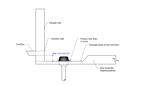

11.1.4.3. Membrane Gutters
(See Note A-11.1.4.3.)
- A RoofStar Guarantee may cover a membrane gutter only when the membrane gutter and the adjoining roof area are part of the same scope of work (gutters lined with an adhered membrane and typically integrated into the roof structure).
- The Design Authority is responsible to design the membrane gutter for its anticipated capacity, with consideration given to
- rainfall and snow load calculations for the building location,
- drain type, size, and flow rate, and
- size and placement of the overflow drain.
- New membrane gutters shall be designed with a minimum width of 304.8 mm (12”) and a depth not exceeding the gutter’s width.
- At least 101.6 mm (4") clearance on the horizontal plane is required between any membrane gutter wall and the
- the edge of the drain bowl for spun drains, and
- the edge of the drain leader for flat spun or welded drains.
- Only fully-adhered membranes may be used in membrane gutters.
- Metal gutter liners are permissible, provided they are designed to fit over acceptable waterproofing, and the liners conform to the material requirements in Article 11.2.1.3.
- Conventionally insulated systems that drain into a membrane gutter must abut solid blocking at the gutter edge, which provides
- a stop for the insulation assembly, and
- a solid substrate for the securement of flashings and membranes.
- An overflow drain must be located at least
- 101.6 mm (4”) above the primary membrane gutter drain, and
- 25.4 mm (1”) below any mechanical fasteners used to secure the adjoining roof system.
- In roof replacement applications, existing membrane gutters may qualify for a RoofStar Guarantee, but should be redesigned if their capacity is undersized, and must incorporate an overflow drain in keeping with the requirements in this Part.
- Where the primary drain in an existing membrane gutter is undersized for its capacity, the primary drain must be replaced with one that is properly sized.
- When a membrane gutter adjoins a RoofStar-guaranteed water-shedding system, the transition from gutter to roof system shall conform to Article 11.3.3.8.
11.1.4.4. Drains in Planters
- Drains designed for structural planters must conform to the requirements in Article 6.1.3.2. of the “RGC Standard for Vegetated Roofs”.
Section 11.2. Materials
(See Division C, "Accepted Materials")
11.2.1. Material Properties
11.2.1.1. General Requirements
- Except for cast-iron roof drains, which are usually supplied and installed by others, only new drains and penetration flashings listed in Division C may be used.
- All roof drains and overflows must conform to CSA ASME A112.6.4-2022/CSA B79.4-2022, "Roof, deck, and balcony drains", unless otherwise permitted by the Guarantor.
- Reuse of any penetration flashing or drain (except serviceable cast iron drains) is prohibited and may void the Guarantee (See Division A, Article 3.2.1.2.).
- Where drains or overflows are fabricated from stainless steel, the stainless steel shall be Grade 316L and shall conform to ASTM A240/A240M-22a, “Standard Specification for Chromium and Chromium-Nickel Stainless Steel Plate, Sheet, and Strip for Pressure Vessels and for General Applications”.
- Sheet membranes used to flash (strip in) drains shall be reinforced with polyester or a composite scrim, but in any event must conform to the membrane requirements found in Article 9.2.1.1.
11.2.1.2. Roof Drains and Scuppers
(See Note A-11.2.1.2.)
- All roof drains
- must be designed and manufactured for roof applications only, and shall not be floor drains, and
- shall be made so that the roof membrane can be sealed to the drain body or bowl (the membrane seal must not rely solely on a clamping ring).
- Cast-iron primary roof drains
- must be supplied with a sump receiver and under-deck clamp,
- should separate securement of the under-deck clamp and clamping ring from securement for the strainer, and
- must be installed by the trade supplying the roof drain.
- Cast-iron planter drains must be supplied with a perforated riser that is proprietary to the drain manufacturer (See the “RGC Standard for Vegetated Roofs”, 6.1.3.2).
- Cast-iron scupper drains must be
- supplied with a clamping strainer, and
- designed with cast, enclosed (captive) strainer bolt receivers (drains with bolts exposed on the back side of the drain body are not acceptable).
- Lead sheet flashing, when specified, must be sized to extend past the drain bowl by at least 152.4 mm (6”), and must have a weight of at least 15 kg/m2 (3 lb/ft2).
- All primary flanged insert drains (drains with a stem that inserts into a drain leader)
- must be manufactured with a hot-welded or seamless flange at least 101.6 mm (4”) wide (measured from the outer edge of the drain opening),
- must be hot-welded at the joints between the bowl/flange and drain stem, and
- should incorporate a clamping ring (a clamping ring is recommended for primary flanged insert drains specified on any project), but clamping rings are required when primary flanged insert drains are specified for a RoofStar 15-year Guarantee.
- Primary flanged drains (insert drains or scuppers) that connect with plumbing inside the building (“internal” drains) must be constructed of
- copper (min. weight: 24 oz. sheet copper; min. thickness: 20-gauge, or 0.889 mm (0.035”)),
- aluminum (min. thickness: 12-gauge, or 2.053 mm (0.08081”)), or
- stainless steel, Grade 316L (min. thickness: 18 gauge, or 1.27 mm (0.050”)).
- Primary flanged drains (insert drains or scuppers) that drain directly to the exterior of the building (“external” drains) must be constructed of
- copper (min. weight: of 16 oz.; min. thickness: 24-gauge, or 0.559 mm (0.022”)), or
- aluminum (min. thickness: 20-gauge material, or 0.812 mm (0.03196”)).
- All scupper drains (open, or closed (boxed)) must be
- manufactured with welded seams and joints,
- designed to extend past the outside face of the wall, and
- fabricated from
- copper (min. weight: 16 oz.; min. thickness: 24-gauge, or 0.559 mm (0.022”)),
- aluminum (min. thickness: 20-gauge material, or 0.812 mm (0.03196”)), or
- stainless steel, Grade 316L (min. thickness: 18 gauge, or 1.27 mm (0.050”)).
- In addition to the general requirements for scupper drains, closed (boxed) scupper drains must also be
- fully enclosed on four sides, for through-wall applications,
- fabricated with a drip edge at the bottom outside edge of the drain to deflect overflow water away from the building, and
- fitted with an overflow opening on the outside face of the scupper,
- equal in capacity to the main drain leader opening, and
- at least 38.1 mm (1 ½”) lower than the top surface of the scupper drain.
- Overflow drains
- must be manufactured from copper or aluminum conforming to the material requirements in Sentence (9) above, but
- may be manufactured from ferrous metals (See Section 13.2.), and
- may be manufactured from stainless steel, but the steel shall be Grade 316L stainless steel (min. thickness: 20 gauge, or 0.9525 mm (0.0375”)), and
- must have a hot-welded or seamless flange at least 101.6 mm (4”) wide when measured from the outer edge of the drain opening.
- must be manufactured from copper or aluminum conforming to the material requirements in Sentence (9) above, but
- All roof drains utilized in a roof assembly that includes gravel ballast or growing media (soil) must be supplied with the drain manufacturer's proprietary primary drain strainer and secondary stainless-steel ballast guard, but when one is not provided, a custom-fabricated guard may be used provided the guard
- is fabricated from 20-gauge stainless-steel (0.9525 mm or 0.0375”),
- incorporates 6.35 mm (1/4”) perforations, and
- equals or exceeds the height of the finished system surface.
11.2.1.3. Membrane Gutters and Gutter Liners
- Membrane gutter membranes shall be
- accepted by the Guarantor,
- acceptable to the manufacturer,
- compatible with the adjoining roof system, and
- manufactured for full adhesion (semi-adhesion and mechanical securement are not permissible).
- A reinforced liquid membrane system (PMMA or PUMA) approved for field use and applied to an accepted SBS-modified base membrane is acceptable as a gutter membrane.
- A metal gutter liner
- may be fabricated from
- copper sheet material, incorporating soldered seams, or
- stainless steel, incorporating welded seams, and
- must conform to the sheet metal requirements in Article 13.2.1.2.
- may be fabricated from
11.2.1.4. Fasteners
- Mechanical fasteners used to secure the roof membrane and penetration flashings, or related accessories, must be
- properly sized in accordance with roof system securement requirements (See Part 3), and
- self-drilling purpose-made screws manufactured with deep, recessed heads.
11.2.1.5. Sealants
- Sealants must be manufactured by, or acceptable to, the manufacturer.
- Compression sealants must be formulated to provide waterproofed seals under compressive loads.
11.2.1.6. Liquid Membrane Flashing
- Only a RoofStar-accepted reinforced two-component catalyzed polymethyl methacrylate (PMMA) liquid membrane flashing system may be used on the water plane to flash roof drains, scuppers, and overflows.
Section 11.3. Application
11.3.1. Guarantee Term Requirements
11.3.1.1. RoofStar 5-year Guarantee and RoofStar 10-year Guarantee
- To qualify for a RoofStar 5-year Guarantee or RoofStar 10-year Guarantee, all projects shall comply with the requirements in this Part.
11.3.1.2. RoofStar 15-Year Guarantee
- To qualify for a RoofStar 15-year Guarantee, all projects shall comply with the requirements in this Part for a RoofStar 5-year Guarantee or RoofStar 10-year Guarantee, and shall
- incorporate overflow drains in all roof areas,
- utilize only primary drains and overflows manufactured with clamping rings, and
- ensure the roof membrane is secured with drain clamping rings or, when specified, with a reinforced 2-component liquid membrane flashing applied to conform to the requirements in this Part.
11.3.2. All Systems
11.3.2.1. Condition and Suitability of Roof Drains
- All clamping rings and strainers must be unbroken, properly seated, and fully secured.
11.3.2.2. Location and Spacing of Roof Drains
(See also Section 11.1., "Design")
- Roof drains for new construction projects must be located at least 457.2 mm (18") away from any adjacent drain, penetration, upstand, edge, or wall (the separation space is measured between openings, excluding the flange).
- The 457.2 mm (18") spacing requirement for roof drains does not apply to overflows, scupper drains, and drains used in membrane gutters.
- Roof drains and cap membrane seams must be offset from each other at least 304.8 mm (12”), measured from the edge of the drain.
11.3.2.3. Drain Protection Against Blockage
- All roof drains must be supplied and installed with a secured strainer to prevent debris from blocking the drain.
- When a roof supports overburden or is secured with ballast, drains must be installed together with a surrounding ballast guard that promotes water flow.
- When the overburden is a vegetated roof system, roof drains must be protected by both a stone/ballast guard and a separation zone, as required in Article 5.1.3.3. of the "RGC Standard for Vegetated Roofs" .
11.3.2.4. General Installation Requirements
- Roof drains must be
- secured to the supporting deck structure, or to blocking, and
- properly detailed for continuity with specified control layers.
- When a roof supports overburden or is secured with ballast, drains must be installed together with a surrounding ballast guard that promotes water flow.
- Drains must be flashed using the primary membrane system or accessories acceptable to the manufacturer and the Guarantor.
- When fleece-reinforced liquid membrane systems are used to flash drains, only a RoofStar-accepted reinforced two-component catalyzed polymethyl methacrylate (PMMA) may be used on the drainage plane to flash roof drains, scuppers, and overflows.
11.3.3. Drains and Membrane Gutters
(The requirements for Subsection 11.3.2., "All Systems", shall be read together with the following Articles)
11.3.3.1. Drain Sumps
- When a 2-part liquid membrane flashing is specified for reinforcement of drain sumps, the liquid membrane flashing must continuously cover the sides of the sump, overlapping both the sump bottom and the roof field by at least 101.6 mm (4”).
11.3.3.2. General Requirements for Cast-iron Roof Drains
- Cast-iron roof drains must be installed by the plumbing/mechanical trade.
- When cast-iron roof drains are used, a sump receiver and under-deck clamp must be provided and installed by the trade supplying the roof drain.
- Drain extensions for cast-iron roof drains should be avoided.
- Existing flow control removed during roof construction should be reinstalled; however, if the replacement roof will support a vegetated roof system, the drainage design must conform to the requirements set out by the Design Authority.
- All cast-iron roof drains must be
- new or clean,
- unbroken (this applies to the clamping ring also), and
- flashed in accordance with the manufacturer's published instructions, or to the requirements published in this Part, whichever are greater.
- The continuity of air and vapour control layers must be maintained, where the controls are specified.
11.3.3.3. Cast-iron Drains Installed with Lead Flashing
- All roof system components, including tapered insulation, must be cut to fit closely around the drain bowl and leader.
- The drain flange must be clean and dry.
- The base field membrane must
- neatly fit around the outside edge of the cast drain flange, and
- be prepared to receive a coat of membrane-compatible mastic, as directed by the manufacturer’s published instructions.
- A membrane-compatible mastic must be applied to the field membrane, and to the drain flange.
- The lead flashing must
- be centred over the drain body,
- extend inside drain bowl at least 25.4 mm (1"), and
- conform to the contours of the drain bowl.
- A reinforcement membrane ("target") patch of modified bituminous base sheet material, 3 mm or more in thickness, must
- measure at least 1m x 1m (39” x 39”),
- be applied over the lead flashing and onto the field base membrane, ensuring continuous visible bleed-out of bitumen around all edges of the patch and a firm bond between the membrane and the lead flashing, and
- must extend at least 152.4 mm (6”) past the outside edge of the lead flashing.
- The cap field membrane must be installed according to the general requirements for field membranes (See Article 9.3.2.3.).
- The cap membrane must extend past the inside edge of the drain bowl.
- The clamping ring must be seated and secured, ensuring it is not broken.
- The drain screen must be securely installed.
11.3.3.4. Cast-iron Drains Installed with Membrane Flashing
- All roof system components, including tapered insulation, must be cut to fit closely around the drain bowl and leader.
- The drain flange must be clean and dry.
- When priming is required by the manufacturer, the drain flange must be primed with the manufacturer’s accepted primer.
- The field membrane system must be installed according to the requirements in Article 9.3.2.3.
- In addition to the manufacturer’s specific requirements for roof drains,
- the base field membrane must be prepared to receive a reinforcement membrane patch,
- a reinforcement membrane ("target") patch of modified bituminous base sheet material, 3 mm or more in thickness, must
- measure at least 1m x 1m (39” x 39”),
- be applied over the drain flange and onto the roof field, ensuring continuous visible bleed-out of bitumen around all edges of the patch and a firm bond between the membrane and the drain flange,
- the membrane patch must be trimmed to the inside edge of the drain bowl, and
- must extend at least 152.4 mm (6”) past the outside edge of the clamping ring,
- the cap field membrane must
- be installed according to the general requirements for field membranes (See Article 9.3.2.3.), and
- extend past the inside edge of the drain bowl,
- the clamping ring must be seated and secured, ensuring it is not broken, and
- the drain screen must be securely installed.
11.3.3.5. Cast-iron Roof Drain Retrofitting (Replacement Roofing)
- Retrofitting a cast-iron roof drain is not recommended, but when retrofitting is unavoidable (i.e., the drain has deteriorated to the extent that it cannot receive a new roof membrane, and removal is not possible),
- remove any broken parts and debris,
- connect the retrofit insert to internal leaders using only an external coupling (unless impractical - see alternative requirements below), and
- follow the requirements set out in Article 11.3.3.2.
- When an internal compression seal is used out of necessity to connect a retrofit drain to an existing drain leader,
- the joint must be properly prepared to ensure the joined surfaces are clean, smooth, and uniform, and
- honing out the cast pipe may be required.
- In the absence of a clamping collar, the retrofit insert drain must be sealed to the primary membrane with another method acceptable to the manufacturer and the Guarantor (Ref. Article 11.2.1.6.).
11.3.3.6. Flanged Insert-type Roof Drains
- Flanged insert drains must be
- installed after the primary field base membrane has been fully installed,
- embedded in a continuous trowelled bed of mastic, applied to a prepared compatible base membrane where the flange makes contact,
- mechanically fastened to blocking, or to the roof deck, using fasteners conforming to Article 11.2.1.4.,
- pre-primed on both faces of the flange, before installation of a reinforcement membrane patch, and
- sealed to the field base membrane with a reinforcement membrane ("target") patch
- at least 3 mm thick,
- large enough to extend past the edge of the drain flange by at least 152.4 mm (6”),
- aligned with the base field membrane runs, or oriented 45-degrees to the base field membrane,
- cut to terminate on the flange, and
- sealed onto the flange and the field base membrane, evidenced by continuous visible bleed-out of bitumen along all edges of the patch,
- The cap field membrane must overlap the base membrane patch and be heat-welded or adhered to the drain flange, at the bowl.
- Only mechanical compression type seals may be used to connect insert-type drains to internal drain leaders; “O”- rings, mastics and caulking are not acceptable methods for sealing these types of drains to leaders.
11.3.3.7. Scuppers and Overflows
- Open scupper drains may be constructed to match the height of the roof or membrane gutter edge, but must be fully sealed with membrane flashing (Ref. Construction Detail "Open-wall Scupper Drain").
- When a through-wall scupper is specified, only fully enclosed scupper drains (enclosed on all sides and open only at the inflow and outflow ends) may be installed (Ref. Construction Detail "Through-wall Scupper Drain").
- Scuppers and overflows that are installed through walls may be installed no closer than 203.2 mm (8") to
- a roof drain, or
- any protrusion and its flashing.
- Scupper and overflow assemblies must be
- cleaned and prepared to receive membrane flashing (refer to the membrane manufacturer’s published requirements),
- embedded in a layer of trowelled membrane-compatible mastic,
- primed on exposed flanges to receive membrane flashing,
- mechanically fastened to the substrate (i.e., blocking, the roof deck, and the wall) with fasteners conforming to Article 11.2.1.4., and
- sealed to the roof system with base sheet membrane flashing plies that
- lap onto the drain body flanges at least 101.6 mm (4”), and
- extend onto the surrounding field membrane or perimeter base membrane by at least 152.4 mm (6").
- Cap sheet membrane flashing for scuppers and overflows must extend past the terminated edges of base membrane plies and seal to the drain flange.
- Clamping collars must be securely installed according to their design, and where specified.
11.3.3.8. Membrane Gutters
- All gutter membranes must be installed according to the manufacturer’s published instructions.
- Sheet membranes installed in a gutter must be
- installed perpendicular to the gutter length,
- carried up an adjoining roof system (measured vertically from the maximum water level)
- at least 152.4 mm (6”), or
- at least 304.8 mm (12”) in regions with typical heavy snow,
- lapped under and sealed to the adjoining membranes at least 152.4 mm (6”),
- installed in keeping with application requirements in this Standard,
- mechanically secured at their terminations, both on the outside of the gutter edge and on the field, and
- secured above the maximum water level at least 152.4 mm (6”) and no more than 304.8 mm (12”) O.C.
- Gutter drains and overflows must be installed in keeping with the requirements in Section 11.1., "Design".
- Drain flanges that must be bent to accommodate the width of the gutter must be mechanically fastened to the gutter wall before membrane is installed.
- A metal gutter liner
- must incorporate soldered seams when it is fabricated from copper sheet material,
- must incorporate welded seams when it is fabricated from stainless steel, and
- must be installed
- over an adhered single ply membrane, no less than 2.3 mm (90 mils) thick (bituminous membranes) or 1.5 mm (60 mils) thick (non-bituminous membranes), and
- with a separation layer (slip sheet) between the membrane and the metal liner to prevent damage to the membrane caused by the liner at its joints.
- The transition from a membrane gutter to a water-shedding system that is insulated (typically ASM only) shall conform to the requirements for membrane gutters in the "Standard for Architectural Sheet Metal (ASM) Roof Systems" (See Construction Detail "Membrane Gutter (Design Elements)" for an illustrated example).
Part 12 - Penetrations and Curbs
Section 12.1. Design
12.1.1. General
12.1.1.1. Scope
- The scope of this Part and the Standard shall be as described in Division A, Part 1.
12.1.1.2. Defined Terms
- Words that appear in italics are defined in the Glossary.
12.1.2. Guarantee Term Requirements
12.1.2.1. RoofStar 5-year Guarantee and RoofStar 10-year Guarantee
- To qualify for a RoofStar 5-year Guarantee or RoofStar 10-year Guarantee, all projects shall comply with the requirements in this Part.
12.1.2.2. RoofStar 15-Year Guarantee
- To qualify for a RoofStar 15-year Guarantee, all projects shall comply with the requirements in this Part for a RoofStar 5-year Guarantee or RoofStar 10-year Guarantee; in addition,
- when a roof is replaced, all open-top penetration flashings (flashings without a top cover) must be waterproofed as described elsewhere in this Part and shall be installed with clamped double storm collars that are fully sealed around the upper edge,
- when a roof is installed on a newly constructed building, all penetration flashings that are usually fitted with a single storm collar (typically supplied and installed by others) must be fitted with a second storm collar, supplied by the Contractor,
- all electrical, gas, and other services, that penetrate the roof assembly must be protected against water intrusion with
- purpose-made flashings that are sealed into the roof system,
- curbs fitted with a “weather head” hood sealed into the curb membrane flashing, or
- sealant pockets (used only where unavoidable) that conform to this Part and are at least 101.6 mm (4”) tall, or are elevated the same distance above the water plane (when measured from the water plane to the top of the pocket), and
- when penetrations or vent openings in a conventionally insulated roof system are flashed using galvanized or hot-welded materials, the flashings
- must conform to the requirements in Section 12.2.,
- shall be elevated on curbs, and
- must be additionally flashed ("coated") with a reinforced catalyzed two-component liquid membrane, or with two (2) cured applications of a single-component liquid flashing system (See Article 12.3.2.2.).
12.1.3. All Systems
12.1.3.1. General Requirements for Penetrations
- Where openings or penetrations pass through the roof assembly (i.e., for mechanical or electrical services), the specification and detail drawings shall
- provide direction for continuity of control layers, where these layers intersect with any opening or penetration, and
- require a curb or an acceptable penetration flashing to enclose and seal each roof opening.
- Each penetration (except for clustered or bundled electrical cables) must be flashed separately from others.
- Single or bundled electrical cable penetrations must be flashed with a suitable goose-neck flashing, fitted with a weather head.
- Penetration flashings must be
- new,
- suitable for the type of penetration, and
- properly sized and fitted around the penetration to permit a seal (gaps between the penetration and the inside of the flashing shall be no more than 12.7 mm (1/2"), or
- of sufficient height to be made water-tight with a site-fabricated membrane seal fashioned to enclose the gap between the flashing and the penetration (see Figure 12.3.2.1.-A); the application of liquid sealant around the penetration in an open-top flashing is not acceptable.
- Hollow steel penetrations and structures that penetrate the roof system should be filled with spray foam.
- Hollow steel penetrations and structures that are manufactured with vent holes (necessary during galvanizing) must be fitted with lead plugs in the holes to prevent water ingress (plugs should be cut flush with the outside face of the penetration).
- Penetration flashings
- that are or may be prone to condensation should be factory-insulated, and
- should be selected for their ability to inhibit the intrusion of vermin and insects into the roof assembly and building interior.
- Suitable flashings must be specified for penetrations that are expected to expand, contract, or otherwise move.
- Cylindrical ("pipe-type") penetrations must be sealed with
- the manufacturer’s proprietary pre-moulded flashing that utilize mechanical clamps,
- a 2-part site-fabricated or proprietary flashing with a removable inspection/access cap (Ref. Construction Detail "2-Part Retrofit Flashing (Cable Penetration)"), or
- roof curbs fitted with customized metal hoods or square-to-round metal flashing.
- Aluminum or copper flashings for penetrations may be located at the drainage plane in any assembly type.
12.1.3.2. Galvanized Penetration Flashings
- Galvanized flashings and vents may be specified for use in the drainage plane on uninsulated or conventionally insulated systems, provided they conform to the requirements and conditions in Article 12.3.2.2.
- All galvanized penetration flashings or vents specified for use in a protected roof system or modified protected roof system must be located on curbs no less than 203.2 mm (8") in height above the finished system surface.
- Galvanized flashings with a base opening larger than 0.126 m2 (196 in.2) in size must be supported by a curb.
12.1.3.3. Separation Between Details
- Penetrations on new construction projects must be separated from
- other penetrations, curbs, walls, or changes in plane at least 304.8 mm (12") (this is measured between openings or the edge of a detail and excludes the flashing flange), and
- all roof drains at least 457.20 mm (18") (Also see Article 11.1.3.2.).
- Penetrations that are closer together than the stated minimum, and which are flashed with a single customized flashing or curb are exempt from the requirement in Sentence (1).
- When the separation between details does not comply with the spacing requirements in this Part, only the alternate application methods described in Sentences (17) through (19) of Article 12.3.2.1. will be permitted by the Guarantor.
- Where alternate methods are not available in this Standard, or where the space between penetration flashings and any change in plane (e.g., curb, sleeper, parapet) is less 203.2 mm (8”), a Variance request shall be submitted to the Guarantor by the Design Authority following the Variance requirements in Article 1.1.3.6.
12.1.3.4. Curbs, Sleepers, and Equipment Pads
- The design and placement of curbs and sleepers shall be the responsibility of the Design Authority.
- Curbs must be designed so that they can be secured directly to the deck structure, or to intermediate blocking, and must not be situated on top of the roof system.
- All curbs, sleepers, and deck-supported equipment pads must be designed to achieve a minimum height of 203.2 mm (8”), measured from the finished system surface, to permit proper membrane flashing.
- Notwithstanding the minimum height requirement membrane flashing, curbs and sleepers that are completely sealed (enveloped) with membrane, and are free of penetrations through the top face (i.e., equipment isolators) may be less than 203.2 mm (8”) in height but shall be
- no less than 101.6 mm (4") in height, or
- no less than 127 mm (5") in height when capped with a linear metal flashing.
- Equipment isolators are not considered part of the roof system and therefore any leaks caused by or occurring at isolators shall be excluded from coverage under the Guarantee.
- Equipment ("housekeeping") pads placed on top of the finished system surface and supporting combined loads
- less than 90 kg (200 lbs) must be separated from the membrane with a bond-breaking layer (i.e., XPS insulation), and
- greater than 90 kg (200 lbs) must conform to the requirements for structural sleepers or equipment pads.
- Reinforced liquid membrane flashing systems may be specified only where
- sheet membrane applications are not practicable (i.e., complex geometry), or
- the top edge of membrane plies must be terminated on a vertical surface and other means of termination are not practicable or even possible.
- Curbs enclosed within or adjacent to a vegetated roof system shall be designed with base metal flashings to retain the root barrier and any other system components that must be turned up the vertical surface; base flashings shall be fabricated and installed in keeping with the requirements in Part 13 (See Articles 13.1.3.6., 13.2.2.1., and 13.3.2.3.; also see Clause (1)(8) of Article 10.3.2.5., “Installation of Root Barrier”, in the "RGC Standard for Vegetated Roofs").
12.1.3.5. Protection of Roof Membranes
- The Design Authority must consider and specify mitigating strategies to preserve the membrane from damage (i.e., specifying grease guards or a reinforced 2-part liquid membrane coating) when mechanical equipment extracts and discharges grease, chemicals, or other contaminants, onto the roof.
12.1.3.6. Railings, Ladders, and Other Attached Structures
- Railings, ladders, and other attached structures shall not be affixed at the field membrane level and should be designed for attachment to vertical surfaces only.
- Attachment of railings, ladders, and other attached structures to a raised horizontal substrate is strongly discouraged, but when this manner of securement is specified, the design must be submitted in writing by the Design Authority to the Guarantor for review and acceptance through a written Variance.
- Ladders, railings, or other structures that may penetrate the roof system, should be designed to minimize thermal bridging (and consequential condensation) or reduced thermal performance; uninsulated direct, rigid connections to the structural deck or walls is strongly discouraged.
- Pourable sealant pockets used to flash vertical penetrations should be specified only as a last resort, for use only when other flashing methods are impractical (Ref. Article 12.3.2.8., "Sealant Pockets").
Section 12.2. Materials
(See Division C, "Accepted Materials")
12.2.1. Material Properties
12.2.1.1. Membranes Used for Flashing
- Sheet membranes used to flash (strip in) penetrations and curbs shall be
- the same membrane used on the roof field, or
- sheet or liquid membranes conforming to Article 10.2.1.1.
12.2.1.2. General Requirements for Penetration Flashings
- All roof penetration flashings, except flashings that are proprietary to the manufacturer and flashings that are installed or supplied by others as part of a Code-compliant, certified chimney assembly (i.e., for solid fuel heating appliances), must be
- accepted by or acceptable to the Guarantor,
- manufactured to conform to CSA-B272, "Prefabricated Self-Sealing Roof Vent Flashings" (a penetration flashing fabricated by the Contractor is exempt from this requirement),
- permanently marked with the standard number it conforms to, which shall be independently validated through published testing by a qualified third-party,
- manufactured from sheet metal conforming to the material requirements in Section 13.2., when the flashing is custom-made or fabricated by the Contractor,
- compatible with the roof system,
- seamless or, in the alternative, fabricated with fully hot-welded joints, including a base flange at least 101.6 mm (4”) wide,
- capable of inhibiting the intrusion of vermin and insects into the roof assembly and building interior, and
- at least 203.2 mm (8”) tall when measured from the finished system surface to an opening, or to the top of the flashing.
- Metal penetration flashings that are purpose-made for
- electrical cables must be goose-necked and supplied with a downward-facing weather head, and
- plumbing vents shall be supplied with a matching settlement cap produced by the same manufacturer.
- Galvanized penetration flashings, and galvanized vents, must
- meet or exceed the CSA-A93 Standard,
- be made with material galvanized steel (26-gauge or heavier) conforming to the metal requirements found in Part 13, "Linear Metal Flashing", and
- be at least 203.2 mm (8”) tall when measured from the finished system surface to an opening.
- In addition to the requirements in Sentence (1), stainless-steel penetration flashings specified for corrosive environments should be made of Grade 304 stainless steel conforming to ASTM A240/A240M-22a, “Standard Specification for Chromium and Chromium-Nickel Stainless Steel Plate, Sheet, and Strip for Pressure Vessels and for General Applications”, but when the penetration flashings may be subjected to regular or constant exposure to or immersion in water (especially in a coastal environment), or to corrosive environments, the stainless steel shall be Grade 316L (conforming to the same ASTM standard) (See Note A-13.2.1.2.(3)(2)).
- Storm collars
- must be fashioned from galvanized or stainless steel,
- must slope downward from the penetration approximately 45°,
- shall be at least 50.8 mm (2”) wide,
- shall be self-locking or, in the alternative, manufactured to receive a mechanical band clamp, and
- should be fabricated with a channel at the top edge, for retaining sealant.
- EPDM used to form a seal between a penetration and its flashing (Ref. Article 12.3.2.1.(12)) shall be semi-cured and possess a nominal thickness of no less than 60 mils.
- Unshielded flexible mechanical couplings used to join a flashing and a pipe penetration shall be
- certified to meet ASTM C564 or ASTM D5926,
- certified to meet ASTM C1173 and CSA-B602,
- supplied with top and bottom proprietary screw-type stainless steel mechanical clamps,
- leak-proof, resistant to chemicals, UV-stable, and
- suitable for the penetration and flashing they join together.
12.2.1.3. Flashings for Heating and Plumbing System Penetrations
- All plumbing vent flashings shall be non-ferrous.
- Lead plumbing vent flashings must each be
- fabricated with sheet lead material weighing no less than 14.65 Kg/m2 (3lb/sf),
- properly sized for the pipe, and
- supplied with a settlement cap made from the same materials (the inside collar of the settlement cap must fit vertically inside the pipe opening by at least 25.4 mm (1”)).
- In addition to the general requirements in Article 12.2.1.2., all metal penetration flashings (except natural airflow vents) used for heating and plumbing penetrations must be
- properly sized for the penetration, both in diameter and height,
- flexible or sloped to suit the roof slope, and
- supplied with a properly sized galvanized storm collar or settlement cap.
12.2.1.4. Liquid Membrane Flashing
- Polymethyl methacrylate (PMMA) and polyurethane methyl methacrylate (PUMA) liquid membrane flashing systems must be
- catalyzed 2-component systems,
- fleece-reinforced with the manufacturer's proprietary polyester fleece, and
- accepted listed in Division C of this Manual.
- Single-component polyurethane and silicon-based liquid membrane flashing system must be listed in Division C.
- Accessory PMMA detailing products
- must be listed in Division C, and
- must be reinforced with chopped or loose reinforcement fibres supplied by the manufacturer.
Section 12.3. Application
12.3.1. Guarantee Term Requirements
12.3.1.1. RoofStar 5-year Guarantee and RoofStar 10-year Guarantee
- To qualify for a RoofStar 5-year Guarantee or RoofStar 10-year Guarantee, all projects shall comply with the requirements in this Part.
12.3.1.2. RoofStar 15-Year Guarantee
- To qualify for a RoofStar 15-year Guarantee, all projects shall comply with the requirements in this Part for a RoofStar 5-year Guarantee or RoofStar 10-year Guarantee, and shall comply with the requirements in Article 12.1.2.2.
12.3.2. All Systems
12.3.2.1. General Requirements for Flashing Penetrations
- All penetration flashing materials must be new.
- Anything that penetrates through the roof assembly, including openings in walls and for ventilation, must be
- sealed to each control layer that it passes through or intersects, and
- flashed with
- a flashing proprietary to and supplied by the membrane manufacturer ,
- a curb,
- a purpose-made flashing, or
- a custom-fitted flashing.
- Except for flashings that are proprietary to and supplied by the membrane manufacturer, all flashings for penetrations in the roof field shall be sealed to the roof system so that the penetration or opening is protected from water ingress, to at least 203.2 mm (8") above the finished system surface.
- Each roof penetration must have its own flashing (except where a purpose-made flashing is designed for multiple penetrations), and each flashing
- must be suitable for the slope and penetration,
- shall be fitted with a cap, hood, weather-head, or closure fitting,
- shall not be left open to the weather, insects, or vermin, and
- must be properly sized and fitted around the penetration to permit a seal.
- Except for storm collars, or where sealant pockets are permitted (Article 12.3.2.8.), the use of sealants to make a penetration watertight where it exits a flashing is not acceptable .
- Pipe penetrations in the roof field (e.g., plumbing vents) that are not flashed with the membrane manufacturer’s proprietary pre-moulded boot flashing (applicable only when the roof membrane is EPDM, TPO, or PVC)
- must be at least 203.2 mm (8”) high, when measured from the finished system surface,
- must be flashed with a spun flanged flashing at least 203.2 mm (8”) high, when measured from the finished system surface,
- shall match the height of the flashing opening (pipes that are too short must be extended in a watertight manner), and
- shall be enclosed at the opening with a cap, supplied by the flashing manufacturer, that fits inside the pipe penetration and snugly fits around the outside of the flashing tube (caps should not be mechanically fastened to the flashing).
- Where pre-moulded flashings supplied by the membrane manufacturer are installed around penetrations, the installation must conform to the manufacturer's published requirements and, when the flashing is a moulded pipe boot, the flashing shall be sealed around the top edge and clamped with a stainless-steel mechanical band clamp (Refer to the plumbing vent Construction Detail in Division D).
- Hollow steel penetrations and structures with vent holes from the galvanizing process (e.g., ladders that are anchored to the roof deck and penetrate the roof system) must be plugged with lead to prevent leaks.
- Non-ferrous penetration flashings and vents that conform to the material requirements in Section 12.2. may be located at the drainage plane in any assembly type.
- Lead penetration flashings are not permitted when roof membranes are torch-applied.
- All penetration flashings must be clean, dry, absolutely free of contaminants, have an exterior finish that is suitable to receive sheet or liquid membrane flashing, and must be prepared in keeping with any surface preparation requirements published by the membrane manufacturer.
- Cable and horizontal pipe penetrations must be flashed with
- a purpose-made flashing (i.e., a goose-neck flashing fitted with a weather head),
- a sheet membrane-flashed curb fitted with a customized sheet metal hood (shaped to function like a weather head), or
- a 2-component fleece-reinforced liquid membrane flashing as described in Article 12.3.2.6. (when other methods are not possible or practicable).
- Cables and piping (tubing) passing through a penetration flashing should be drooped (when possible), or fitted with a capillary-breaking collar and sealed at any openings, to prevent water from tracking along the cable or pipe, or to prevent wind-driven rain from entering the flashing, into the building; water that enters a building in this way bypasses the roof system and does not constitute a leak, and is therefore excluded from coverage under the Guarantee (See Figure 12.3.2.1.A and 12.3.2.1.-B).
Figure 12.3.2.1.-A Flexible penetration
showing drip loop and sealant
Forming Part of Sentence 12.3.2.1.(13)
(Click to expand illustration)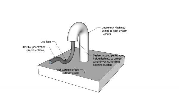
Figure 12.3.2.1.-B Piping (tubing) penetrations
through curb and metal hood flashing
Forming Part of Sentence 12.3.2.1.(13)
(Click to expand illustration)
- Each flanged penetration flashing must be installed after the field base membrane and shall be
- primed, when required by the manufacturer,
- embedded in the manufacturer’s approved adhesive, sealant, or mastic,
- securely fastened to the supporting deck structure or intermediate blocking (See Note A-12.3.2.1.(14)(4)), and
- sealed to the base field membrane with
- its own sheet membrane target patch (the use of a single target patch for multiple penetration flashings is not permissible unless otherwise stated in this Standard - See Figure 12.3.2.1.-C), or
- membrane flashing (retrofit flashings only).
Figure 12.3.2.1.-C
Penetration Spacing and Target Patch
for Flanged Penetration Flashings
Forming Part of Sentence 12.3.2.1.(9)
(Click to expand illustration)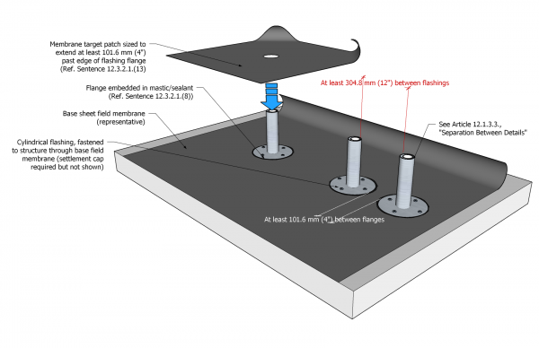
- When penetration flashings are closer than 457.2 mm (18") to a roof drain, the drain must be flashed with a target patch first so that the membrane target patch around the penetration flashing promotes positive drainage; once sealed in with target patches, the field cap sheet membrane may be installed.
- When the separation between penetration flashings is less than 304.8 mm (12") but greater than 203.2 mm (8") (Ref. Article 12.1.3.3.), the penetrations must be
- flashed together with a single membrane target patch that extends at least 152.4 mm (6") past the edge of the flashing flanges,
- capped with the field membrane, and
- additionally sealed at the base of the flashing tube with fleece-reinforced PMMA
- conforming to the application requirements in Article 12.3.2.6.,
- carried up the penetration flashing at least 101.6 mm (4"), and
- carried onto the field cap sheet membrane at least 203.2 mm (8").
- When the separation between penetration flashings is less than 203.2 mm (8"), the penetrations must be waterproofed
- with a curb,
- by elevating the penetrations above the drainage plane, or
- with another method acceptable to the Guarantor (See Note A-12.3.2.1.(13)(4)).
- When the space between penetration flashings and any change in plane (e.g., curb, sleeper, parapet) is less than 304.8 mm (12") but equal to or greater than 203.2 mm (8”) (See Article 12.1.3.3.), the target patch for the penetration flashing shall be installed prior to any membrane flashing at the plane transition, to ensure the target patch forms a seal with the field membrane at least 101.6 mm (4”) wide.
- When the space between penetration flashings and any change in plane (e.g., curb, sleeper, parapet) is less 203.2 mm (8”), a Variance shall be requested from the Guarantor, by the Design Authority, as indicated in Article 12.1.3.3., following the requirements in Article 1.1.3.6.
- Sheet membrane target patches applied over flanged penetration flashings shall be
- cut from a single piece of base sheet membrane (when the penetration is large, the target patch may be cut from two pieces of membrane that must be joined with laps at least 152.4 mm (6”) in width,
- sized to extend past the edge of the flashing flange onto the roof field by at least 101.6 mm (4") (for non-conforming penetration spacing, see Sentence (12) in this Article),
- aligned with the base field membrane runs, or be turned 45-degrees to the base field membrane,
- sealed to the entire flange, terminating approximately 12.7 mm (1/2") from the flashing upstand, and
- sealed to the field membrane beyond the edge of the flashing flange, as evidenced by continuous bleed out of bitumen along all edges of the patch (Ref. Article 9.3.2.6. concerning seams).
- Cap membrane installed over a flanged penetration flashing
- shall extend past the edge of the target patch membrane and terminate at the flashing upstand, and
- must be sealed along the cut edge of the membrane with
- a compatible mastic embedded with granules, or
- a reinforced 2-component liquid membrane flashing, applied in keeping with the standards found in Article 12.3.2.6.
- Retrofit flashings (metal flashings fitted together around a penetration and riveted or clamped together) shall be flashed with
- base sheet membrane flashing carried up the vertical face of the flashing at least 203.2 mm (8") and past the base flange at least 101.6 mm (4"), and
- cap sheet membrane flashing which fully covers the base sheet flashing and extends past the termination of the base flashing by at least 50.2 mm (2")(Ref. Construction Detail "2-Part Retrofit Flashing (Cable Penetration)").
- Where a purpose-made flashing does not fit the penetration (i.e., a penetration that is a square post), or when a penetration extends above the top edge of the flashing so that it cannot be enclosed with a cap See Figure 12.3.2.1.-D), the gap between the penetration and the flashing must be bridged and sealed
- by wrapping the joint with a properly-sized piece of semi-cured EPDM (or its equivalent),
- loosely wrapped around the penetration and the flashing at least 1-1/2 times, or adhered to itself and overlapped at least 50.8 mm (2"),
- installed free of wrinkles or fish-mouths,
- applied so that it extends on either side of the joint by at least 50.8 mm (2"), and
- clamped at the top and at the bottom using stainless steel clamps set back from the membrane edge no more than 6.35 mm (1/4"), or
- with heat-shrink tubing that
- extends onto both the flashing and the penetration by at least 50.8 mm (2"),
- is secured with stainless steel mechanical clamps installed at each end of the tubing, and
- is caulked with an acceptable sealant (when adhesive-lined heat-shrink tubing is used, the sealant may be omitted).
- by wrapping the joint with a properly-sized piece of semi-cured EPDM (or its equivalent),
Figure 12.3.2.1.-D
Alternate Flashing of Pipe Penetration
Forming Part of Sentence 12.3.2.1.(23)
(Click to expand illustration)
- Penetrations that are flashed but are not immediately sealed using the methods described above must be temporarily protected from the weather with at least one properly fitted, level storm collar.
- Unshielded flexible mechanical ("MJ") couplings
- shall be clamped to the penetration and its flashing, and sealed along the top edge with an acceptable sealant, and
- are suitable for use only with penetrations that will not expand, contract, or move with anticipated building settlement, i.e., fall protection anchors.
- On a vertical penetration where a seal cannot be made between the flashing and the penetration (i.e., where the penetration is a hot pipe, or where movement of the penetration is anticipated), the opening between the penetration and top of the flashing must be protected with
- at least one storm collar, secured with a separate mechanical (screw-type) clamp, or
- no fewer than two storm collars, each manufactured with friction-type clips, and spaced approximately 25.4 mm (1") apart.
- All installed storm collars must be sealed with a continuous, untooled bead of acceptable sealant at least 9.53 mm (3/8”) wide, applied to and centered over the joint between the collar and the penetration.
- Reinforced liquid membrane flashing systems may be used (where permitted in Article 12.3.2.6.) to seal a penetration on, or within 203.2 mm (8") of, the drainage plane, but only where
- the penetration is structurally attached to a solid roof deck (concrete or mass timber) and the penetration will not move, shrink, or expand, or
- the penetration is structurally independent of the roof deck, but is of the same type of material (i.e., steel post passing through a steel deck), and
- sheet membrane applications are not practicable (i.e., complex geometry), or
- the top edge of sheet membrane plies must be terminated on a vertical surface and other means of terminating them are not practicable or even possible.

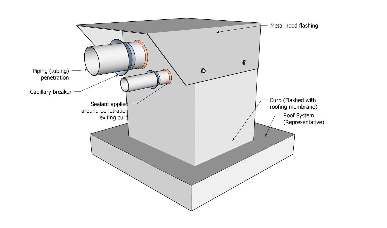
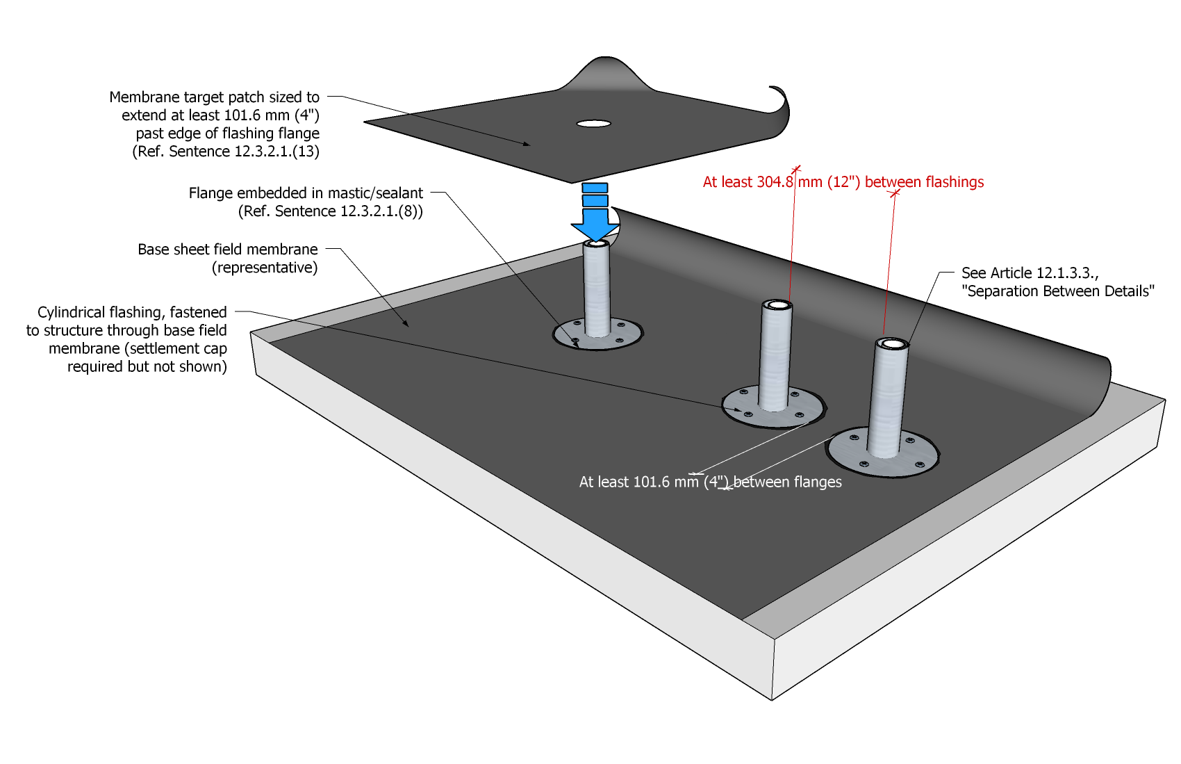
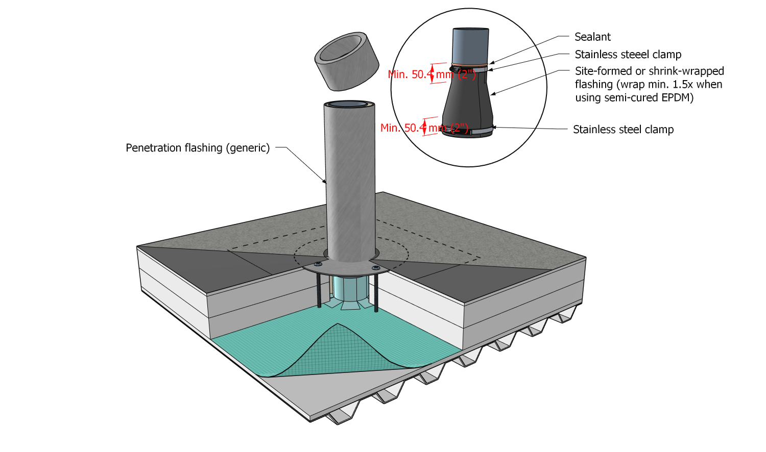
12.3.2.2. Galvanized Penetration Flashings
- Galvanized, hot-welded flashings and vents installed on the drainage plane of uninsulated or conventionally insulated systems
- are permissible provided the base opening of the vent does not exceed 0.126 m2 (196 in.2),
- may be uncoated, provided the roof is sloped at least 1:50 (1/4” in 12”), or the flashing is located in a well-drained area, and
- shall be coated with a liquid flashing system conforming to the application requirements in this Article, when
- the roof is sloped less than 1:50 (1/4” in 12”),
- the flashing is located in a valley, or
- the flashing will be regular exposed to or submerged in water.
- All galvanized penetration flashings or vents specified for use in a protected roof system or modified protected roof system shall not be installed at the drainage plane and instead must be located on curbs no less than 203.2 mm (8") in height above the finished system surface.
- A liquid flashing system applied to flashings and vents
- may be a 2-component PMMA system or a single-component liquid flashing system,
- must be listed in Division C and acceptable to the Guarantor for this application,
- shall be acceptable to the membrane manufacturer,
- shall be applied evenly and with straight lines,
- must extend up the sides of the vent or flashing at least 101.6 mm (4") above the finished system surface, and
- must cover the edge of the sheet membrane where it forms a seal with the flashing.
- Two cured applications of a single-component liquid flashing system are recommended for enhanced durability, but when a single-component liquid flashing system is specified for a RoofStar 15-Year Guarantee, two (2) cured coats are required (Ref. Article 12.1.2.2.).
12.3.2.3. Separation Between Penetration Flashings
- Penetrations on new construction projects must be separated from
- other penetrations, curbs, walls, or changes in plane so that the space between flashings for these details is at least 304.8 mm (12") (this is measured between openings or the edge of a detail and excludes the flashing flange), and
- roof drains at least 457.20 (18") (Also see Article 11.1.3.2.).
- When the separation between penetration flashings does not conform to the minimum spacing requirements, the application options described in Article 12.3.2.1. must be followed.
12.3.2.4. Curbs, Sleepers, and Equipment Pads
- Sheet membrane flashing for curbs must provide continuous waterproofing from the roof field up the vertical plane, at least 203.2 mm (8”) above the finished system surface and shall conform to the requirements in Article 10.3.2.3., unless otherwise specified or permitted in this Part; waterproofing of equipment installed on a curb (i.e., isolators and other mounts) is the responsibility of others.
- Curb, sleeper, or equipment pad sheet membrane flashing
- shall be fully adhered to its substrate,
- base plies must lap onto the field base membrane by at least 101.6 mm (4"), or extend at least 50.8 mm (2") past perimeter mechanical fastener plates installed on the field, whichever is greater,
- cap plies must lap onto the field cap membrane at least 50.8 mm (2") past the end of base membrane flashing plies,
- base and cap plies must be carried up a vertical surface, above the finished system surface, at least 203.2 mm (8") (the exception to this requirement is fully-enveloped sleepers or equipment pads),
- must be hand rolled with a membrane manufacturer’s accepted roller, and
- shall be secured to the substrate by the Contractor where membrane terminates on a vertical substrate.
- All inside and outside corners of sheet membrane-flashed curbs or walls must be reinforced with membrane gussets, each gusset measuring at least 101.6 mm x 152.4 mm (4” x 6”), excluding the tapered ends.
- Exposed membrane edges on curbs must be protected from UV radiation, and from water intrusion, using a counter-flashing or options described in Article 10.3.2.3.
- When installing heat-welded membranes, or where construction sequencing requires it, alternatives to conventional membrane flashing should be considered (Ref. Article 12.3.2.5.).
- Reinforced liquid membrane flashing systems shall conform to the requirements in Article 12.3.2.6., and may be used only
- where sheet membrane applications are not practicable (i.e., complex geometry), or
- where the top edge of membrane plies must be terminated on a vertical surface and other means of termination are not practicable or even possible (See also Article 12.3.2.6.).
- Sleepers or equipment pads that are completely sealed (enveloped) with sheet membrane must be at least 101.6 mm (4") in height above the finished system surface, but when fully enveloped sleepers or equipment pads are capped with linear metal flashing, they must be at least 127 mm (5") in height above the finished system surface to provide sufficient height for exposed fasteners.
- All penetrations through the top surface of a sleeper or equipment pad must be sealed using
- a compression sealant between the membrane and equipment supports, and
- a universal sealant applied around the edges of equipment supports.
- Equipment ("housekeeping") pads placed on top of the finished system surface and supporting combined loads
- less than 90 kg (200 lbs) must be separated from the membrane with a bond-breaking layer (i.e., XPS insulation), and
- greater than 90 kg (200 lbs) must be waterproofed to conform to the requirements for structural sleepers or equipment pads in this Section.
12.3.2.5. Alternative Approaches to Membrane Flashing
- The Contractor must assess the best approach to waterproofing any detail, when site conditions or construction sequencing require alternatives to heat-welding.
- When alternative methods are required,
- curbs must be flashed by adapting the methods described in Article 10.3.8.2., or by using other approaches that are equal or superior, and
- penetrations must be
- incorporated into an adhered or self-adhered field membrane system, or
- flashed by using a pre-flashing method that is suitable for the penetration.
12.3.2.6. Liquid Membrane Flashing
(See Figures 12.3.2.6.-A and 12.3.2.6.-B)
- Any liquid flashing system shall
- conform to the material requirements in Article 12.2.1.4.,
- be compatible with the substrate to which it is applied,
- be applied to a properly prepared substrate, which must be clean, dry, free of contaminants, and primed, all as required by the manufacturer in their published instructions,
- be applied within masked boundaries to produce clean, straight, plumb edges (accessory products may be exempt from this requirement only when masking is impracticable),
- be used only when permitted by the manufacturer, and
- be applied in keeping with the requirements and limitations of this Article.
- Liquid membrane flashing systems may not be used on plastic substrates.
- When liquid membrane flashing systems are required or specified, only two--component fleece-reinforced catalyzed polymethyl methacrylate (PMMA) and polyurethane methyl methacrylate (PUMA) liquid membrane flashing systems may be used
- on the drainage plane,
- where sheet membrane flashing may not be practical or even possible,
- to terminate the top edge of sheet membrane flashing,
- where resistance to contamination of sheet membrane is necessary,
- where abrasion resistance is required, or
- for sheet membrane reinforcement (i.e., at corners).
- Two-component fleece-reinforced catalyzed polymethyl methacrylate (PMMA) and polyurethane methyl methacrylate (PUMA) liquid membrane flashing systems
- may be used
- where abrasion resistance is desirable, or
- where the Design Authority specifies its application.
- shall be applied to ensure that
- the rate of application conforms to the manufacturer's published instructions, unless superseded by this Standard,
- the base coating of catalyzed liquid membrane resin evenly and fully covers the masked area,
- the manufacturer’s reinforcement fleece is cut to cover the masked area, to within 4.76 mm (1/8”) of all edges,
- the fleece is fully embedded in, and saturated with, the based coating of resin, and
- the fleece is evenly and thoroughly coated with a second application of catalyzed liquid membrane resin, covering the masked area.
- may be used
- Where a fleece-reinforced 2-component catalyzed polymethyl methacrylate (PMMA) liquid membrane flashing system is used to terminate sheet membrane on the vertical plane, the liquid membrane flashing system must overlap the sheet membrane, and it must extend onto the vertical substrate above the sheet membrane, by no less than 50.8 mm (2") (Figure 12.3.2.-B).
- Fleece-reinforced 2-component catalyzed polymethyl methacrylate (PMMA) liquid membrane flashing system that is used as a substitute for sheet membrane flashing must be carried up a vertical plane above the finished system surface at least 203.2 mm (8”), and no less than 203.2 mm (8") onto the horizontal field plane (See Figure 12.3.2.6.-A and Figure 12.3.2.6.-B).
- Single-component polyurethane and silicon-based liquid membrane flashing system
- may be used
- to coat galvanized flashings used in the water plane, provided the application follows the requirements in Article 12.3.2.2., "Galvanized Penetration Flashings",
- to flash details more than 101.6 mm (4”) above the water plane, that cannot be sealed with sheet-type membranes, or
- to seal pre-curb dowels (see Article 14.3.2.7.).
- must not be used in the drainage plane, or to reinforce membranes against abrasion,
- must be applied in two cured coats, unless otherwise permitted in this Standard, and
- must be fleece-reinforced between coats where
- the application is considered permanent,
- a change in plane (angle) occurs, or
- there is a joint between two supports and the liquid membrane must serve as a bridge.
- may be used
- Accessory PMMA detailing products
- shall not be used as a substitute for fleece-reinforced 2-component PMMA systems, where these are required or exclusively permitted,
- must be used at locations 101.6 mm (4”) or more above the finished system surface, except where complex details, such as bolt heads, cannot be properly sealed with a fleece-reinforced 2-component PMMA system, and
- must not be used where movement is expected.
Figure 12.3.2.6.-A Application Requirements for PMMA on Roof Penetration
Forming Part of Sentence 12.3.2.6.(6)
(Click to expand illustration)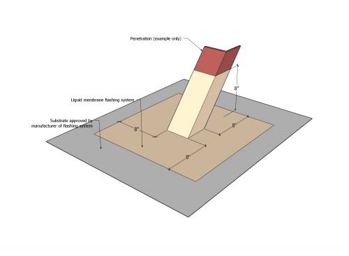
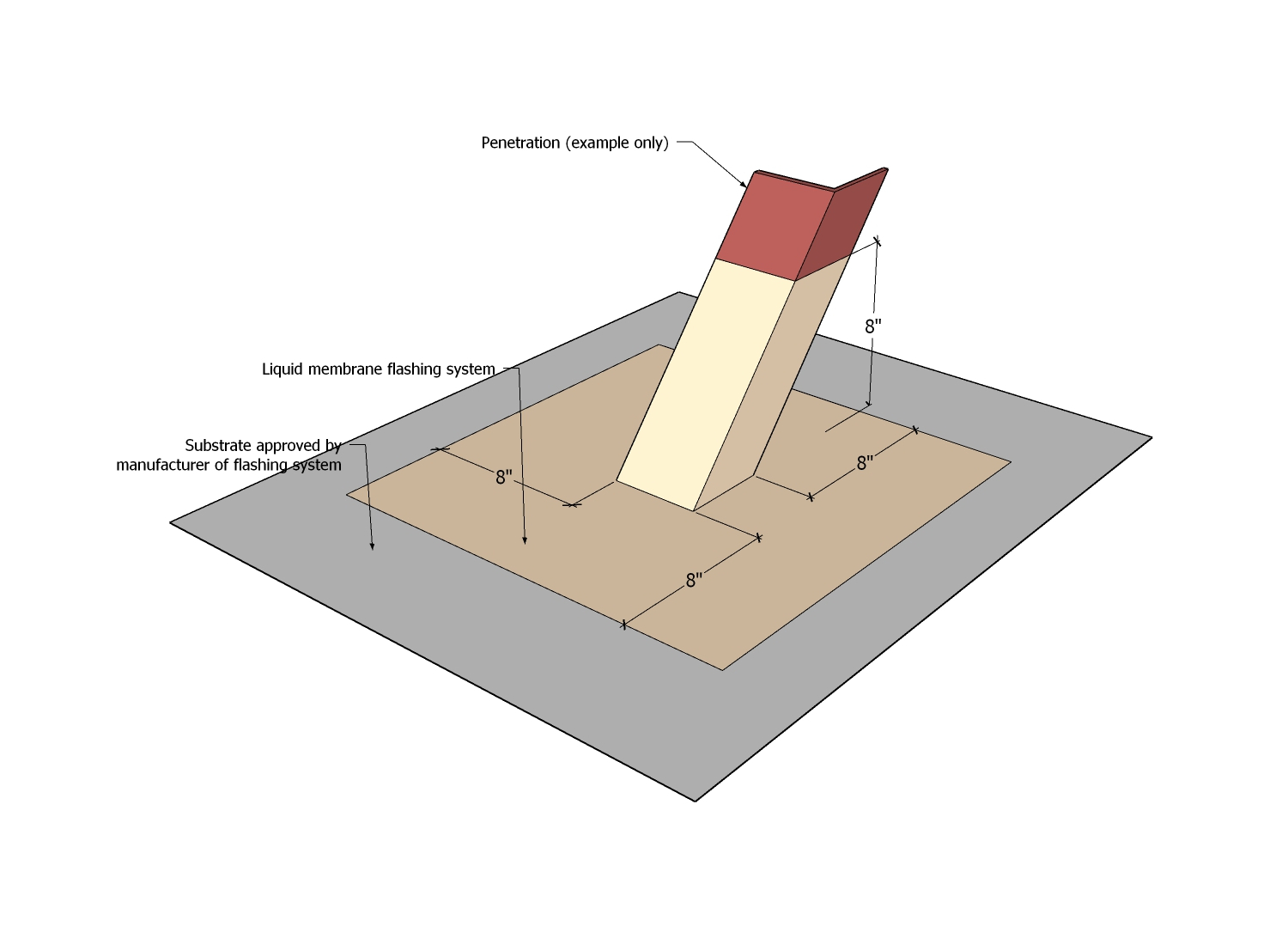
Figure 12.3.2.6.-B Illustration of Various Liquid Membrane Flashing Applications
Forming Part of Article 12.3.2.6.
(Click to expand illustration)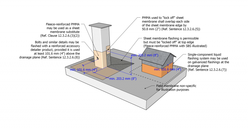

12.3.2.7. Railings, Ladders, and Other Attached Structures
(See also Construction Detail "Railing")
- Fasteners installed to secure railings, ladders, and other structures to the vertical face of walls must be located at least 88.9 mm (3-1/2") above the finished roof surface.
- Railings, ladders, and other structures mounted on a waterproofed horizontal substrate that is part of the roof assembly (i.e., on top of a parapet) shall be fully flashed around each base with a fleece-reinforced liquid membrane flashing material, unless directed otherwise by a written Variance issued by the Guarantor, using a product that is
- suitable for use in the drainage plane,
- applied in keeping with the requirements in Article 12.3.2.6., and
- compatible with roofing membranes installed on the substrate.
- Railings, ladders, and other structures shall not direct water into a roof system by means of weep holes or the method of fastening.
12.3.2.8. Sealant Pockets
- Pourable sealant pockets should be used only when sealing penetration with sheet membranes or reinforced liquid membrane flashing is impractical.
- Sealant pockets must be
- at least 50.8 mm (2”) deep, and
- large enough to provide at least 25.4 mm (1”) of fillable space on all sides of the penetration.
- When pourable sealant pockets are installed,
- the penetration surfaces must be properly prepared following the sealant manufacturer’s instructions, to ensure a good bond between the penetration and the sealant,
- only the membrane manufacturer’s approved proprietary UV-stable urethane-based structural sealants may be used to fill sealant pockets,
- the sealant must be crowned to shed water,
- the sealant pocket shall be sealed to the roof membrane following requirements published elsewhere in this Standard, and
- a site-formed non-bituminous flexible roof membrane storm collar must be fitted and secured to the penetration with stainless steel clamps.
Part 13 - Linear Metal Flashing
Section 13.1. Design
13.1.1. General
13.1.1.1. Scope
- The scope of this Part and the Standard shall be as described in Division A, Part 1.
13.1.1.2. Defined Terms
- Words that appear in italics are defined in the Glossary. Additionally, the following terms are used in this Part:
- Cleat, also referred to as a "wind clip", is a long piece of sheet metal that is fastened to a solid substrate (usually structural) behind a linear metal flashing, to hold it in place .
- Drip edge means the bent (kicked-out) hemmed edge of a linear metal flashing, measuring at least 19.05 mm (3/4") and angled no more than 30° from vertical ("Architectural Sheet Metal Manual" published by the Sheet Metal and Air Conditioning Contractors National Association, Inc. (SMACNA), Sixth Ed.: p. 2.3); it is used to direct dripping water away from the face of the metal flashing or the materials it is protecting, such as a wall. A drip edge may be fabricated on any linear metal flashing but is commonly used on coping (parapet cap) and counter-flashing (also see the Glossary for a colloquial use of the term).
- Hemmed edge means an edge of a linear metal flashing that is folded onto itself (bent 180°), to render a smooth (not raw or sharp) finish (this is sometimes referred to as a "safety edge").
- Linear metal flashing means flashings cut and shaped from flat metal stock, to redirect water at roof perimeters and edges, or to control the flow of water in valleys and drainage spillways. Linear metal flashings also protect roof membranes from weathering and damage and provide an aesthetic finish to the roof system.
13.1.2. Guarantee Term Requirements
13.1.2.1. RoofStar 5-year Guarantee and RoofStar 10-year Guarantee
- To qualify for a RoofStar 5-year Guarantee or RoofStar 10-year Guarantee, all projects shall comply with the requirements in this Part.
13.1.2.2. RoofStar 15-Year Guarantee
- To qualify for a RoofStar 15-year Guarantee, all projects shall comply with the requirements in this Part for a RoofStar 5-year Guarantee or RoofStar 10-year Guarantee, and shall
- include only linear metal flashings fabricated from 24-guage stock (or thicker).
13.1.3. All Systems
13.1.3.1. Scope and Function
(See also the "Architectural Sheet Metal Manual" published by the Sheet Metal and Air Conditioning Contractors National Association, Inc. (SMACNA))
- Linear metal flashings described in this Part and referenced elsewhere in this Standard
- are considered necessary and integral to the scope of a project designed and constructed to qualify for a RoofStar Guarantee,
- do not perform a waterproofing function and therefore must be specified for use over membrane flashing, or designed to shed water onto a waterproofing or water-shedding primary material,
- shall be new (reuse of any existing linear metal flashings is prohibited and may void the Guarantee (See Division A, Article 3.2.1.2., "Limitations and Exclusions of Guarantee"), and
- shall be Contractor-fabricated to suit the project requirements or shall be listed in Division C as materials pre-engineered and manufactured by a metal supplier.
- The requirements in this Part apply almost entirely to Contractor-fabricated linear metal flashings; consequently, RoofStar-accepted pre-engineered products accepted as systems are exempt from the requirements in this Part for metal gauge, profile, and securement, unless expressly stated otherwise.
- Linear metal flashings
- must be specified when UV-sensitive membranes require protection, or when membrane edges will otherwise be exposed to the sun, to water, or to physical damage, and
- may be specified to cover parapet caps, sleepers, or curbs
- for aesthetic reasons, or
- to protect the membrane from damage resulting from maintenance (i.e., pressure washing of decks or pavers), or from foot traffic.
13.1.3.2. Information Required in Specifications
- Subject to the requirements in this Standard, the Design Authority must specify
- metal type, finish, and gauge,
- seam types,
- length of flashings (if different from the requirements in this Part), and
- method of attachment (concealed or exposed fasteners).
- Design drawings must detail metal flashing profiles desired for the project.
13.1.3.3. Securement
- Securement of all linear metal flashings shall be specified in keeping with the application requirements in Article 13.3.2.1.
13.1.3.4. Gauge, Dimension Limitations, and Seams
- Gauge, dimensions, slope, and length of linear metal flashings must be specified to conform to the requirements in Table 13.1.3.4.-A and Article 13.2.1.2., but shall not be less than 26-Gauge.
- Specified seam types shall conform to the requirements in Table 13.1.3.4.-B and Article 13.3.2.2.
Table 13.1.3.4.-A.
Pre-finished Galvanized Steel Cap (Coping) Flashing
(Gauge and Length Requirements )
Forming Part of Sentence 13.1.3.4.(1).
Horizontal Span Minimum
SlopeGauge Maximum Flashing
Segment LengthSeam Options Up to 304.8 mm (12") 2% 26, 24 ≤ 3048 mm (120") S-lock or Standing Seam 22+ Butt Seams* 304.8 - 914.4 mm (12" to 36") 4% 24 ≤ 3048 mm (120") S-lock or Standing Seam 22+ Butt Seams* 914.4 mm (36") or greater 6% 24 ≤ 1219.2 mm (48") S-lock or Standing Seam 22+ Butt Seams* Up to 304.8 mm (12") 2% 24 3048 mm (12"),
as specified by a
registered professionalS-lock or Standing Seam† 22+ Butt Seams* 304.8 - 914.4 mm
(12" to 36")4% 24 S-lock or Standing Seam† 22+ Butt Seams* 914.4 mm (36") or greater 6% 24 S-lock or Standing Seam† 22+ Butt Seams*
- * Ref. Article 13.3.2.2., "Seams"
- † Seam type shall be determined by the registered professional but when the flashing exceeds 3048 mm (120”) in length and linear expansion or contraction will be greater than 6.35 mm (¼”), only S-locks or Butt Seams shall be used.
Table 13.1.3.4.-B.
Pre-finished Galvanized Steel Vertical Flashing
(Gauge and Length Requirements)
Forming Part of Sentence 13.1.3.4.(2).
Vertical Face Gauge Maximum Flashing
Segment LengthVertical Seam Options Up to 152.4 mm (6") 26 ≤ 3048 mm (120") S-lock Up to 203.2 mm (8") 24 ≤ 3048 mm (120") S-lock Up to 304.8 mm (12") 22+ ≤ 3048 mm (120") Butt Seams* Up to 152.4 mm (6") 24 >3048 mm (120”),
as specified by a
registered professionalS-lock*† Up to 203.2 mm (8") 24 S-lock*† Up to 304.8 mm (12") 22+ S-lock or
Butt Seams*†
- * Ref. Article 13.3.2.2., "Seams"
- † Seam type shall be determined by the registered professional but when the flashing exceeds 3048 mm (120”) in length and linear expansion or contraction will be greater than 6.35 mm (¼”), only S-locks or Butt Seams shall be used.
13.1.3.5. Fit and Finish
- Fit and finish of all linear metal flashings shall conform to the requirements in Subsection 13.2.2.
- Drip edges are not required but are strongly recommended for linear metal flashings installed around the outside perimeter of a building, to protect wall finishes (Ref. Article 13.2.2.1. for fabrication requirements).
- Stainless steel flashings and fasteners are recommended for use in environments where significant corrosion may occur(e.g., near salt-water coastlines) (See Article 13.2.1.2. for stainless steel material requirements).
13.1.3.6. Cap Flashing, Counter-flashing, and Reglet Flashing
- Cap (coping) flashings
- are required for all parapets (including parapets on roof areas that are adjacent to each other),
- are optional for roof dividers that are fully enveloped with roofing membrane (Ref. Article 10.3.6.2.), and
- are recommended on roof dividers where the membrane may be susceptible to abrasion or mechanical damage.
- All linear metal cap (coping) flashing specified for parapets shall indicate securement to a solid substrate
- at every seam, using S-locks or standing seam clips (Ref. Article 13.3.2.2., "Seams"),
- beneath the outside vertical face of the flashing, using hidden clips (Ref. Article 13.3.2.3.), and
- on the roof-side (inside) face of the flashing.
- The use of exposed fasteners on the exterior face of cap (coping) flashing specified for parapets is not permissible.
- When the top surface of a wall exceeds 101.6 mm (4") in width, linear metal coping (cap) flashing must be specified with a minimum slope of 2% toward the roof-side of the parapet, to promote drainage (drainage toward the exterior of a building is not recommended).
- All metal cap (coping) flashing must be designed with full, solid support.
- When the specified cap flashing material is thicker or heavier than 18-gauge steel or aluminum, or it exceeds the permissible weight or gauge ranges for copper or zinc flashings, the seam and securement design must be submitted to the Guarantor for review prior to tender (See Article 13.3.2.2. concerning flat butt seams).
- Base metal flashings used to conceal wall materials or to restrain filtration materials and drainage boards must be fashioned to conform to Article 13.2.2.1. and Article 13.3.2.3.
13.1.3.7. Intersections with Other Assemblies
- Where a parapet intersects with a wall, the union must be designed to direct water to the roof, away from the outer surface of the wall, using a metal saddle assembly in combination with the membrane requirements in Article 10.3.4.1. (Ref. Article 13.3.2.3.).
Section 13.2. Materials
(Ref. Division A, Article 3.2.1.2. concerning limitations and exclusions for metal flashing.)
13.2.1. Material Properties
13.2.1.1. Manufacturing and Supply
- Linear metal flashings must be new, manufactured and supplied by the Contractor or by an Associate Member of the RCABC, and must conform to the requirements published in this Part.
13.2.1.2. Sheet Metal Grade and Gauge
- A mill certificate must be provided by the Contractor when requested by the Design Authority.
- When stainless-steel metal flashings are specified, grade 304 stainless steel conforming to the requirements in Clause (3)(2) may be used in most applications but when flashings will be subject to regular or constant immersion in water (especially in a coastal environment), or to corrosive environments, the flashings should be manufactured from Grade 316L stainless steel conforming to the requirements below.
- The following minimum gauges and/or weights of sheet steel materials apply to all linear metal flashings (the reference standard for gauges is USS REV (metric in mm)):
- Galvanized steel: minimum 0.50 mm (0.0196", 26-gauge) galvanized steel sheet, conforming to ASTM A653 / A653M-06 CS Type B, Z275 (G90) coating. Thickness tolerance as per ASTM A924/A924M-06 ±0.08 mm (0.003") for sheet widths not exceeding 1524 mm (60").
- Stainless Steel Grade 304: minimum 0.38 mm (0.014", 28-gauge) stainless steel, Grade 304, conforming to ASTM A240/A240M-22a, “Standard Specification for Chromium and Chromium-Nickel Stainless Steel Plate, Sheet, and Strip for Pressure Vessels and for General Applications”. Maximum thickness tolerance variation ± 0.04 mm (0.0015") based on 1219.2 mm (48") wide sheet (See Note A-13.2.1.2.(3)(2)).
- Stainless Steel Grade 316L: minimum 0.38 mm (0.014", 28-gauge) stainless steel, conforming to ASTM A240/A240M-22a, “Standard Specification for Chromium and Chromium-Nickel Stainless Steel Plate, Sheet, and Strip for Pressure Vessels and for General Applications”.
- Aluminum-Zinc alloy-coated steel: minimum 0.50 mm (0.0196", 26-gauge) aluminum-zinc alloy coated steel sheet, conforming to ASTM A792/A792M-06 CS Type B, AZM150 (AZ50) coating. Thickness tolerance as per ASTM A924/A924M-06 ±0.08 mm (0.003") for sheet widths not exceeding 1524 mm (60").
- The following minimum gauges and/or weights of non-ferrous materials apply to all linear metal flashings:
- Aluminum: minimum 0.80 mm (0.032", 20-gauge) aluminum sheet, utility quality to CSA HA Series - 1975, plain or embossed finish. Maximum thickness tolerance variation ± 0.06 mm (0.0025") based on 1219.2 mm (48") wide sheet.
- Copper: minimum 0.56 mm (24-gauge; 0.0216", 16 oz.) copper sheet, cold rolled roofing copper to ASTM B370-81. Maximum thickness tolerance variation ± 0.09 mm (0.0035") based on 1219.2 mm (48") wide sheet.
- Zinc: minimum 0.80 mm (0.031") zinc Sheet conforming to European standard EN 988-1996. Maximum thickness tolerance variation ± 0.03 mm (0.0012").
- Where a waterproofing system adjoins and "Architectural Sheet Metal System", linear metal flashings must be fabricated from 24-gauge steel stock.
13.2.1.3. Fasteners
- Fasteners must be
- threaded screws, friction-type pins (i.e., for masonry or concrete), plug (inserts), or rivets (where permitted),
- compatible with materials they contact,
- corrosion-resistant,
- specified by the Design Authority, and
- appropriately sized, in both length and thread type, for the material to which they will be secured.
- Nails are not acceptable as fasteners.
- Notwithstanding the requirements in Sentence (1), threaded fasteners used to secure linear metal flashings
- in concealed locations must be at least No. 8, corrosion-resistant screw or expansion fastener with a low-profile head and must be compatible with both the metal flashing material and the substrate.
- in exposed locations must be at least No. 10., shall be gasketed (cladding screws), and must match the colour of the materials they fasten.
- When pre-engineered linear metal flashing systems are specified, fasteners provided by the manufacturer must be used.
- Rivets shall be closed-end, dome-head type, and shall be used only for fastening together linear metal flashings.
13.2.1.4. Sealants
- Sealants shall be
- non-hardening high-quality butyl or polyurethane,
- available in either gun grade or sealant tape form,
- suitable for exterior use and able to resist the effects of weathering, and
- compatible with, and able to adhere to, the materials to which they are applied.
- Sealants shall conform to
- CGSB 19-GP-5M, “Sealing Compound, One Component, Acrylic Base, Solvent Curing”,
- CAN / CGSB-19.13, “Sealing Compound, One Component, Elastomeric, Chemical Curing”,
- CGSB 19-GP-14M, “Sealing Compound, One Component, Butyl-Polyisobutylene Polymer Base, Solvent Curing”, or
- CAN / CGSB-19.24, “Multi-Component, Chemical Curing Sealing Compound”.
13.2.2. Fabrication and Finish
13.2.2.1. Fabrication of Flashing
- Linear metal flashings must be new, must conform to the requirements published in this Part, and shall be manufactured and supplied
- by the Contractor,
- for the Contractor by another Contractor (RCABC Member), or
- by an Associate Member of the RCABC.
- Unless expressly accepted by the Guarantor, all linear metal flashing fabricated by the Contractor shall conform to the requirements in this Part.
- All linear metal flashing, except those that are pre-engineered and expressly accepted by the RGC,
- must be hemmed, and
- shall conform to the minimum requirements in Table 13.1.3.4.-A and 13.1.3.4.-B.
- Slotted holes, to allow for the coefficient of expansion, are recommended for any length of linear metal flashing, where gasketed screws are used to secure it (See Figure 13.2.2.1.-A. Also see Note A-13.2.2.1.(4)).
- The vertical leg of any linear metal flashing that overlaps roofing material
- must be at least 76.2 mm (3") in height, exclusive of the drip or hemmed edge, when measured between each break,
- and shall overlap the edge of a membrane (i.e., membrane flashing on a wall) by at least 25.4 mm (1”).
Figure 13.2.2.1.-A Roof-side face of cap flashing
showing slotted hole for gasketed fastener
Forming Part of Article 13.2.2.1.
(Click to expand illustration)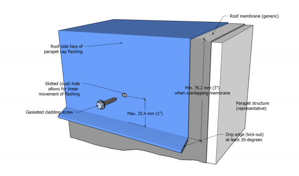
- All hemmed drip edges shall be broken (bent) outward from the face of the flashing by at least 30° (See Figure 13.2.2.1.-B).
- The fabrication of linear metal flashings longer than 3048 mm (120”) is permissible, provided
- galvanized steel flashings are manufactured from metal stock 24-gauge or heavier, and
- the method of securement, regardless of the material, allows for the coefficient of expansion (See Note A-13.2.2.1.(4).
- All Cap (coping) flashing shall be fabricated with a hemmed drip edge at the bottom of the outside vertical face, to receive the cleat (wind clip) (See Figure 13.2.2.1.-B) .
- Cleats (wind clips) must be fabricated with a hooked edge that both matches the angle of the cap flashing drip edge and will fit inside (be enclosed by) it (See Figure 13.2.2.1.-B).
- When the length of cap flashing is equal to or less than 3048 mm (120”), the length of the hemmed drip edge shall be enough to enclose at least 12.7 mm (1/2”) of the cleat (wind clip) (See Figure 13.2.2.1.-A; also see Clause 13.3.2.3.(2)(1)).
- When cap flashing is longer than 3048 mm (120”),
- the cleat (wind clip) for the outside face of a parapet must be
- continuous (discontinuous cleats (wind clips) are not permitted), and
- fabricated from compatible flat metal stock, two gauges heavier than the cap flashing,
- the length of the hemmed drip edge shall be enough to enclose at least 15.88 mm (5/8”) of the hidden clip hook,
- the roof-side face of cap flashing must be fabricated to allow for the coefficient of expansion (See Note A-13.2.2.1.(4):
- If gasketed screws are specified, the flashing must be slotted, based on the engineered securement requirements (See Article 13.3.2.3.).
- If a cleat (wind clip) is specified, the cleat (wind clip) and the drip edge of the flashing shall conform to the requirements for cleat (wind clip) securement on the outside face of the parapet (using hidden clips, which can allow for unfettered expansion and contraction, is considered a best practice);
- seams joining lengths of cap flashing together shall conform to the engineered requirements for the flashing system (See Table 13.1.3.4.-A and Table 13.1.3.4.-B).
and
- the cleat (wind clip) for the outside face of a parapet must be
- With the exception of drip edges, any break in the vertical face of a linear metal flashing to direct water away from the building shall be at least 30° downward (See Figure 13.2.2.1.-B).
Figure 13.2.2.1.-B Counter-flashing and cap flashing
fabrication requirements
Forming Part of Article 13.2.2.1.
(Click to expand illustration)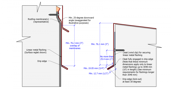
- Base flashing must be fabricated with a drip edge or a flat hemmed edge that, when installed, shall be at least 25.4 mm (1”) above the filtration and drainage course of a protected membrane roof assembly or a vegetated roof system (See Figure 13.3.2.3.-E).
- Metal edge flashing must be fabricated with
- a flange measuring no less than 101.6 mm (4") in width,
- a vertical drop and hemmed drip edge at least 50.8 mm (2"), and (when transitioning to a lower water-shedding systems)
- a sloped drop of no less than 101.6 mm (4").
- Metal edge flashing may be constructed with or without an upstand at the outside edge (Edge flashing intended as a drainage edge may perform best without an upstand).
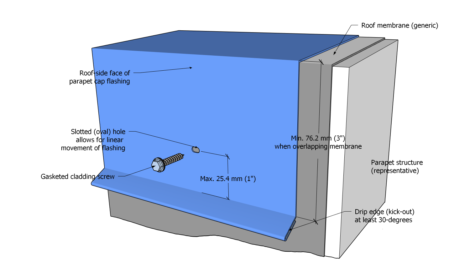

13.2.2.2. Pre-painted Finishes
- When a painted finish on linear metal flashing is specified, only SMP and PVDF pre-painted finishes are acceptable.
- Where Architectural Metal Roofing is installed, adjoining linear metal flashing must have the same finish as the metal panels.
Section 13.3. Application
13.3.1. Guarantee Term Requirements
13.3.1.1. RoofStar 5-year Guarantee and RoofStar 10-year Guarantee
- To qualify for a RoofStar 5-year Guarantee or RoofStar 10-year Guarantee, all projects shall comply with the requirements in this Part.
13.3.1.2. RoofStar 15-Year Guarantee
- To qualify for a RoofStar 15-year Guarantee, all projects shall comply with the requirements in this Part for a RoofStar 5-year Guarantee or RoofStar 10-year Guarantee, and shall
- utilize only (minimum) 24-gauge linear metal flashing material.
13.3.2. All Systems
13.3.2.1. General Requirements for Linear Metal Flashing
- RoofStar-accepted pre-engineered securement systems must be secured according to the manufacturer’s specifications.
- All cap (coping) flashings and other linear metal flashings subjected to wind loads on parapets, roof dividers, firewalls, or any other vertical structure, must be secured to resist displacement by wind load.
- All linear metal flashing installed over an organic substrate (i.e., wood) shall be separated from the substrate with a suitable separation material (i.e., self-adhered bituminous membrane used as eave protection in a water-shedding roof system).
- Unless otherwise provided for in this Part, mechanical fasteners used to secure linear metal flashing or their clips
- shall conform to the fasteners requirements in Article 13.2.1.3.,
- shall be spaced no more than 304.8 mm (12”) O.C.,
- shall be firmly fastened, without distorting secured materials,
- must penetrate the substrate as specified in the screw manufacturer’s published minimum values, but shall nevertheless penetrate
- through the back surface of steel framing at least 19.05 mm (3/4"),
- into or through plywood so that screw threads engage its full thickness, excluding the unthreaded tip, and
- into solid substrate (i.e., dimensional lumber or concrete) at least 25.4 mm (1"), and
- must be installed at least 88.9 mm (3-1/2") above the finished system surface.
- Canted edge metal flashing may be mechanically fastened from the outside face but shall not be face-fastened on the roof side of the flashing.
- Sealants must be tooled to positively shed water.
13.3.2.2. Seams
(The requirements in Article 13.3.2.1., "General Requirements for Linear Metal Flashing", shall be read together with the following requirements. See also Article 13.1.3.4.)
- RoofStar-accepted pre-engineered linear metal flashing may be joined together using seams specified for the accepted flashing.
- All linear metal flashing that is not pre-engineered must be seamed together following the requirements set out in this Article.
- All seams must allow for metal expansion and contraction.
- The seam and securement design must be approved by the Guarantor when the specified cap flashing material
- is steel or aluminum, and the material is thicker or heavier than 18-gauge, or
- is copper and zinc, and the material thickness or weight exceeds the weight or gauge requirements in Article 13.2.1.2.
- Straight (linear) joints between lengths of linear metal flashing must be fully seamed using only a Standing Seam (Figure 13.3.2.2.-A) or S-lock (Figures 13.3.2.2.-B and C), but this requirement does not apply to
- flashing fashioned from 22-gauge metal (or heavier), or
- the vertical face of any flashing that is concealed by a wall assembly, counter-flashing, or equipment flange, in which case the vertical joint may be lap-seamed, provided the overlap
- is no less than 101.6 mm (4”) when fully caulked in the lap, or
- is no less than 152.4 mm (6”) when installed without caulking in the lap.
- The top face (horizontal plane) of flashings that intersect at a corner (i.e., coping flashing) must be joined with a standing seam.
- Where drip edges meet at an outside corner, the cut edges of the mitred joint must be mechanically connected (Closed with a "rat tail").
- When the face of vertically-oriented flashing forms an outside corner, and the height of the flashing
- is greater than 101.6 mm (4”), the two flashings must be joined using only a standing seam.
- is 101.6 mm (4”) or less, the two flashings must be joined using
- a standing seam,
- an S-lock, or
- a lap joint, but the drip edges must be mechanically connected (Closed with a "rat tail").
- When the face of vertically-oriented flashing forms an inside corner, and the height of the flashing
- is greater than 101.6 mm (4”), the two flashings must be joined using only a standing seam.
- is 101.6 mm (4”) or less, the two flashings must be joined using
- a standing seam, or
- a flat overlapped seam.
- Sealant applied to S-lock or standing seams is not a requirement in this Standard, but when it is specified
- the sealant must be applied along the full length of the seam, and
- any sealant that extrudes from the seam during the seaming process must be removed and discarded (See Article 1.3.2.2., "Workmanship").
- Standing seams (See Figure 13.3.2.2.-A) must incorporate clips when the seam is longer than 101.6 mm (4”), and the clips must be
- fabricated from flat metal stock 24-gauge or heavier,
- at least 38.1 mm (1-1/2”) wide,
- spaced apart from each other no more than 203.2 mm (8”) O.C.,
- embedded in an acceptable sealant, and
- secured with at least 2 acceptable low-profile flat head screws.
Figure 13.3.2.2.-A Standing Seam
Forming Part of Sentence 13.3.2.2.(5)
(Click to expand illustration)
- S-locked seams (See Figure 13.3.2.2.-B and Figure 13.3.2.2.-C) must be secured through flashing tab (leaf) with at least one (1) acceptable low-profile flat head screw when the seam is longer than 101.6 mm (4”), but fasteners must not be spaced more than 203.2 mm (8”) O.C.
Figure 13.3.2.2.-B S-Lock, Single
Forming Part of Sentence 13.3.2.2.(11)
(Click to expand illustration)Figure 13.3.2.2.-C S-Lock, Double
Forming Part of Sentence 13.3.2.2.(11)
(Click to expand illustration)

- Flat butt seams (See Figures 13.3.2.2.-C and 13.3.2.2.-D)
- are permissible only for cap (coping) flashings, and only when the flashing is fabricated from steel or aluminum ranging in thickness from 22-Gauge to 18-Gauge (the same applies to the equivalents for copper and zinc sheet material, by gauge or weight), and
- must have a hemmed front edge fabricated to hook onto a supporting saddle.
Figure 13.3.2.2.-C Flat butt seams
Forming Part of Article 13.3.2.2.
(Click to expand illustration)
Figure 13.3.2.2.-D Flat butt seams
Forming Part of Article 13.3.2.2.
(Click to expand illustration)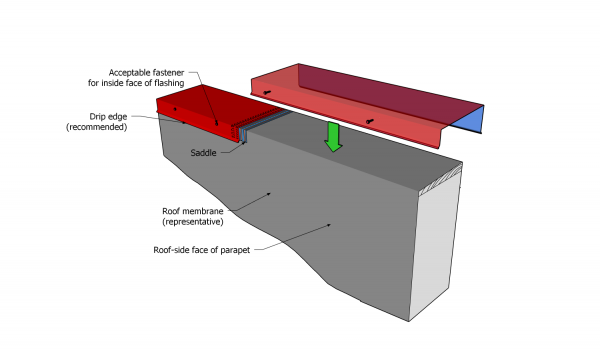
- The saddle for flat butt seams (See Figures 13.3.2.2.-C and 13.3.2.2.-D) must be
- manufactured from the same material as the flashing,
- formed to match the profile of the cap flashing,
- fabricated with a hook along the front face,
- secured to the parapet with screws,
- installed to underlap the butt joint by at least 101.6 mm (4”) on either side,
- seated in two parallel beads of un-tooled sealant or butyl tape, which must be applied between the saddle and flashing, on either side of the butt joint, to all three adjoining faces, and
- secured to the cap flashing along both faces of the parapet (See Article 13.3.2.1.).
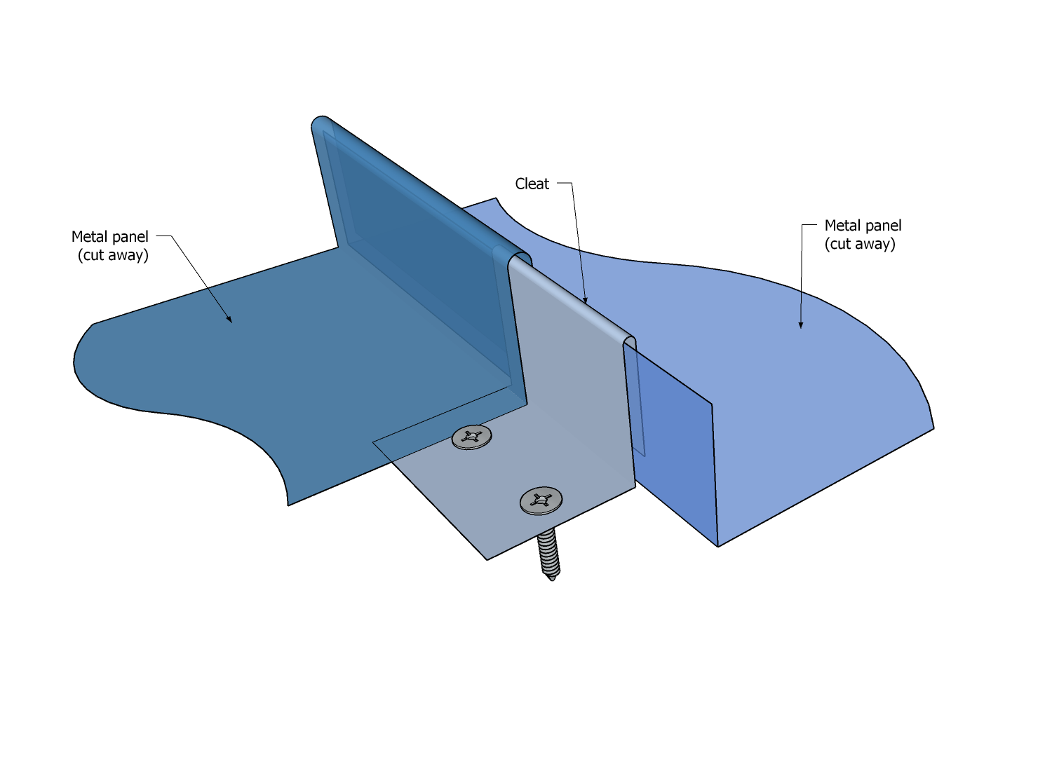
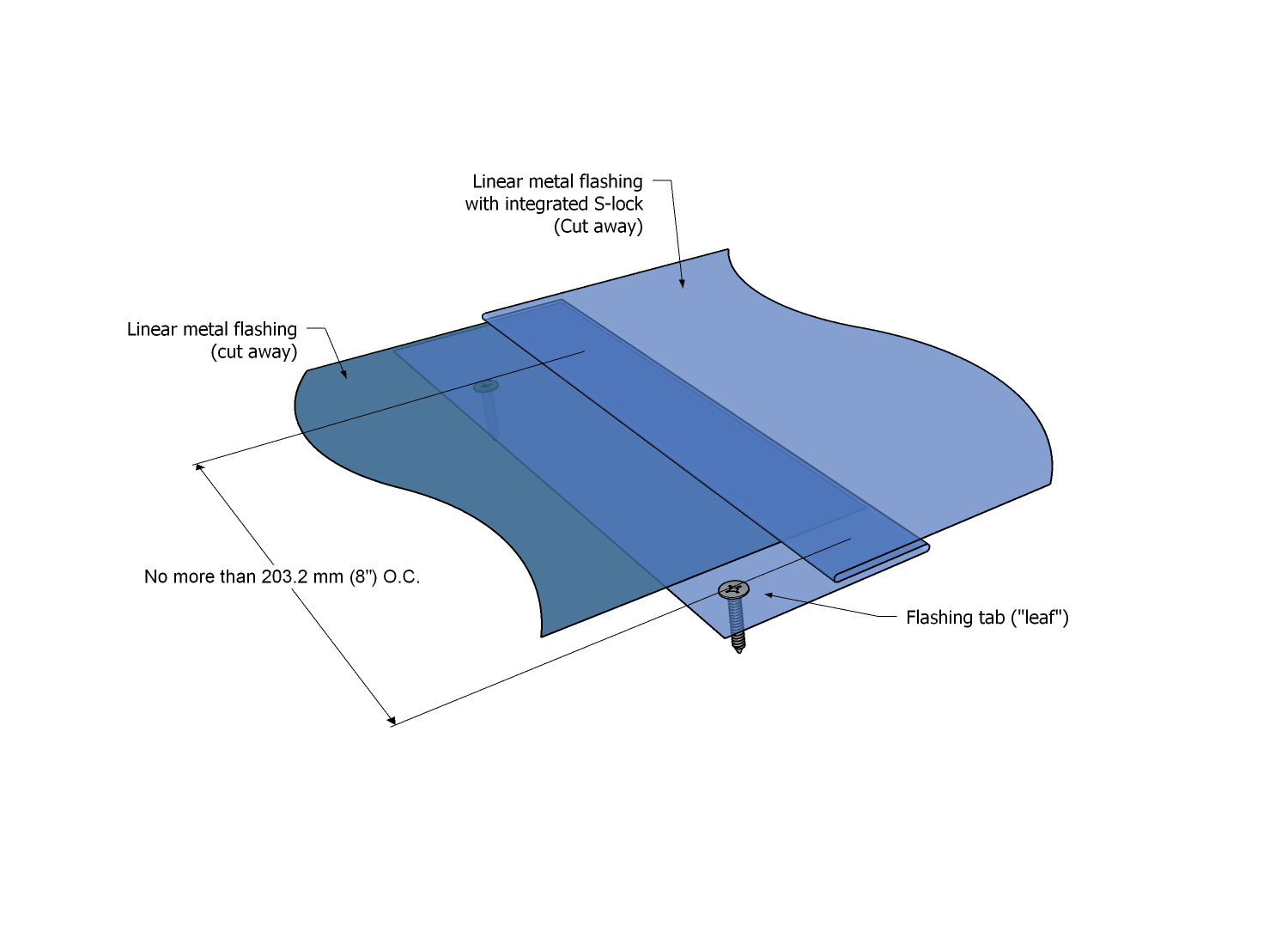
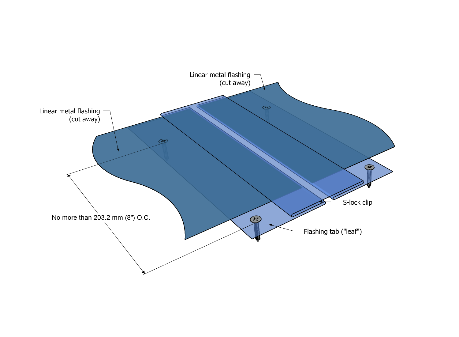
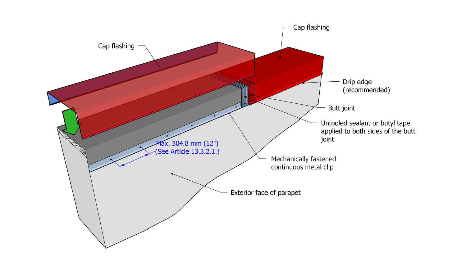

13.3.2.3. Cap Flashing, Counter-flashing, and Reglet Flashing
(The requirements in Article 13.3.2.1., "General Requirements for Linear Metal Flashing", shall be read together with the following requirements)
- Cap (coping) flashings must be
- solidly and fully supported ,
- separated from organic materials (i.e., wood) with roofing membrane, and
- joined using standing seams or S-locks (Ref. Article 13.3.2.2.).
- In addition to the above requirements , cap (coping) flashing installed on parapets
- must be secured to the outside face of the parapet with a cleat (wind clip) that hooks into the drip edge or hem of the cap flashing (See Article 13.2.2.1., "Fabrication"; see also Figure 13.3.2.3.-A).
- shall be secured along the roof-side of the parapet using either cleats (wind clips) or cladding fasteners (the method used shall be specified by the Design Authority or, when required, by a registered professional), and
- shall not be secured to the outside face of a parapet with exposed fasteners.
- Cleats (wind clips) shall be secured to the vertical face of a parapet and shall not be mechanically attached to the top face unless otherwise permitted in this Standard or by a written Variance from the Guarantor.
- Where cleats (“wind clips”) are required, they must
- conform to the fabrication requirements in Article 13.2.2.1., and
- be fastened as close to the bottom edge (hook) as practical but must not be fastened further than a maximum of 25.4 mm (1") from the bottom edge (hook).
Figure 13.3.2.3.-A
General requirements for
cap flashing securement
Forming Part of Article 13.3.2.3.
(Click to expand illustration)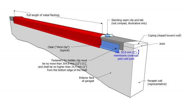
- The securement of parapet cap (coping) flashings longer than 3048 mm (10’) shall conform to stamped, engineered shop drawings produced by a registered professional retained by the Contractor; all shop drawings shall form part of the submittal package required in Article 1.3.2.4., “Contractor Submittals” .
Figure 13.3.2.3.-B
Spacing of gasketed fasteners
used on roof-side face of cap flashing
Forming Part of Article 13.3.2.3.
(Click to expand illustration)
- Cap (coping) flashings installed on control joints (roof dividers) and fire separation walls (Ref. Article 10.3.4.4.) shall conform to the requirements in Sentence (2), and
- may be face-fastened, provided the roof divider or fire separation wall is less than 1 m (39") tall, but
- shall be secured with hidden clips on both sides when the roof divider or fire separation wall exceeds a height of 1 m.
- When using exposed screws to secure cap (coping) flashing is permissible, screws shall be located no more than 25.4 mm (1") above the break for the drip edge and provision shall be made for metal expansion and contraction (See Note A-13.2.2.1.(4) and Figure 13.3.2.3.-C).
Figure 13.3.2.3.-C
Securement of cap flashing
on exterior face of parapet wall
Forming Part of Article 13.3.2.3.
(Click to expand illustration)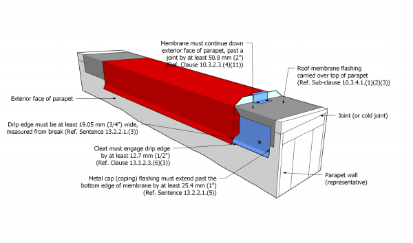
- Exposed fasteners used to secure the roof-side face of cap flashing longer than 3048 mm (10’) shall be equally spaced along the length of the flashing but shall not be further apart than 762 mm (30”) .
Figure 13.3.2.3.-D
Securement of cap flashing
on roof-side of parapet wall
Forming Part of Article 13.3.2.3.
(Click to expand illustration)
- Continuous concealed clips must be attached with fasteners spaced nor more than 304.8 mm (12") O.C.
- Discontinuous concealed clips must
- consist of a single clip, centred between the seams of each length of metal flashing,
- measure at least 1/3 of the length of flashing it will secure but shall not be less than 101.6 mm (4") in length, and
- be fastened with screws spaced no more than 304.8 mm (12") O.C.
- Fasteners used to secure any cap, counter, or base flashing must be evenly spaced between seams along each length of flashing, and shall be
- no fewer than three (3) fasteners for every 3048 mm (120") length of metal flashing (Figures 13.2.3.3.-B and 13.3.2.3.-D), or
- two (2) fasteners for every 2438.4 mm (96") length of metal flashing.
- When cap (coping) flashings span widths greater than 304.8 mm (12”), and a flat butt seam is specified, the cap flashing must be riveted to the saddle to ensure adequate securement, and the rivets must be no further apart than 203.2 mm (8”) (See Figures 13.3.2.2.-A and 13.3.2.2.-B).
- Parapets that intersect a wall must be flashed with a metal saddle flashing, as shown in the "Construction Details for Linear Metal Flashings" ( Division D).
- When the outside face of a cap flashing is concealed by a wall assembly, only the outside face may be lap-seamed, provided the overlap is no less than 101.6 mm (4”) and the overlapping metal is embedded in mastic.
- Counter-flashing must be secured to the vertical face, with fasteners or a reglet.
- Counter-flashing and termination bars installed as primary securement or protection of membrane flashing
- must be hemmed at the top edge and bent (broken) outward from the face of the wall by at least 45°, to form a groove for sealant (The hem shall measure at least 15.88 mm (5/8”) when measured from the break),
- shall be attached to the substrate with fasteners spaced no more than 304.8 mm (12”) O.C., and
- must be sealed along the top groove with a continuous bead of acceptable sealant, tooled to shed water away from the wall.
- A second counter-flashing (to cover a term bar or primary counter-flashing)
- applied as a “surface reglet” must be hemmed, broken, and sealed, as described above in this Article, and
- must be secured with fasteners spaced no more than 304.8 mm (12”) O.C., but this spacing may be increased to no more than 609.6 mm (24”) O.C., provided the flashing maintains continuous contact with the substrate (See Article 13.3.2.1.).
- Base flashings
- must be installed so that the bottom of a drip or hemmed edge is kept at least 25.4 mm (1") above the filtration layer and drainage course of a protected membrane roof assembly or a vegetated roof system (see Figure 13.3.2.3.-E.) ,
- must be secured with fasteners spaced no more than 304.8 mm (12”) O.C., and
- may be fashioned as one piece, or as a 2-piece flashing that includes a lower, detachable segment to facilitate roof maintenance.
Figure 13.3.2.3.-E
Base metal wall flashing
Forming Part of Article 13.3.2.3.
(Click to expand illustration)
- Linear metal flashing secured in a reglet (cut groove) must be
- installed above the membrane flashing,
- inserted into the reglet at least 12.7 mm (1/2”),
- friction-fitted within the reglet or secured on the exposed face with an acceptable fastener, and
- sealed with a continuous bead of tooled gunnable sealant.
- Where parallel and overlapping reglet flashings are used, the joints between flashing segments must be offset by at least 304.8 mm (12”), except at corners.

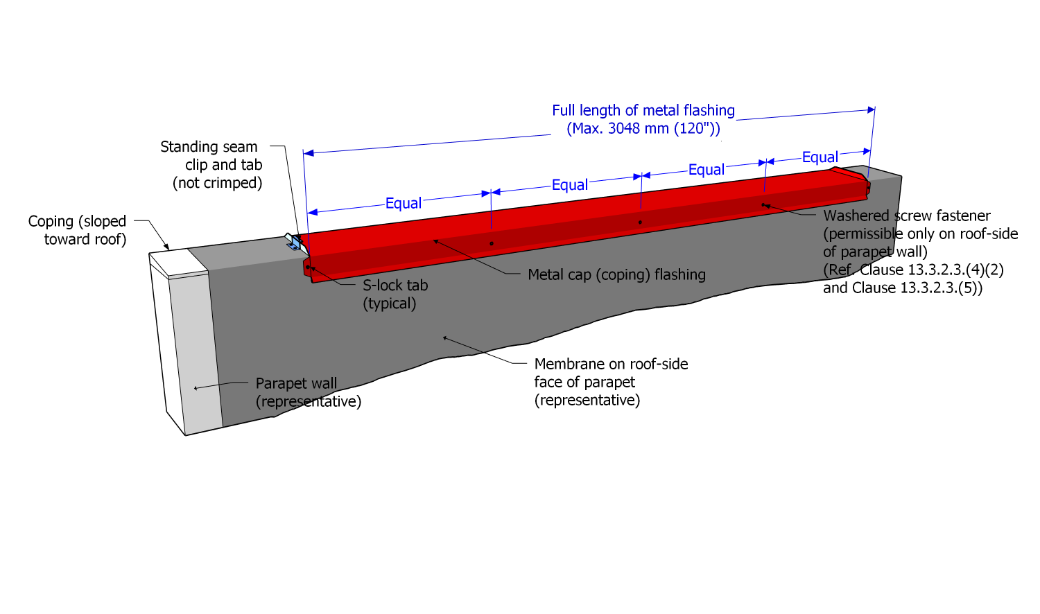
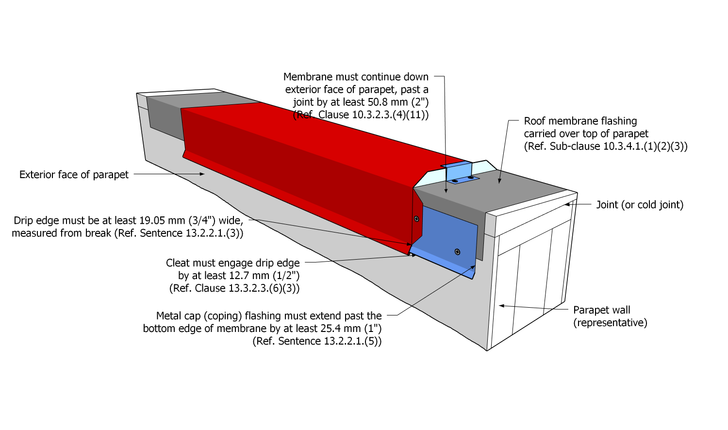
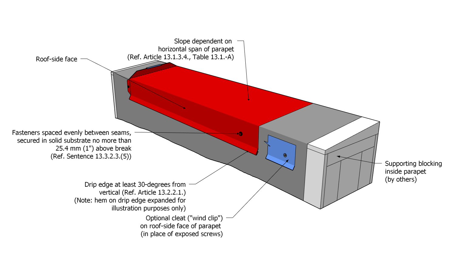
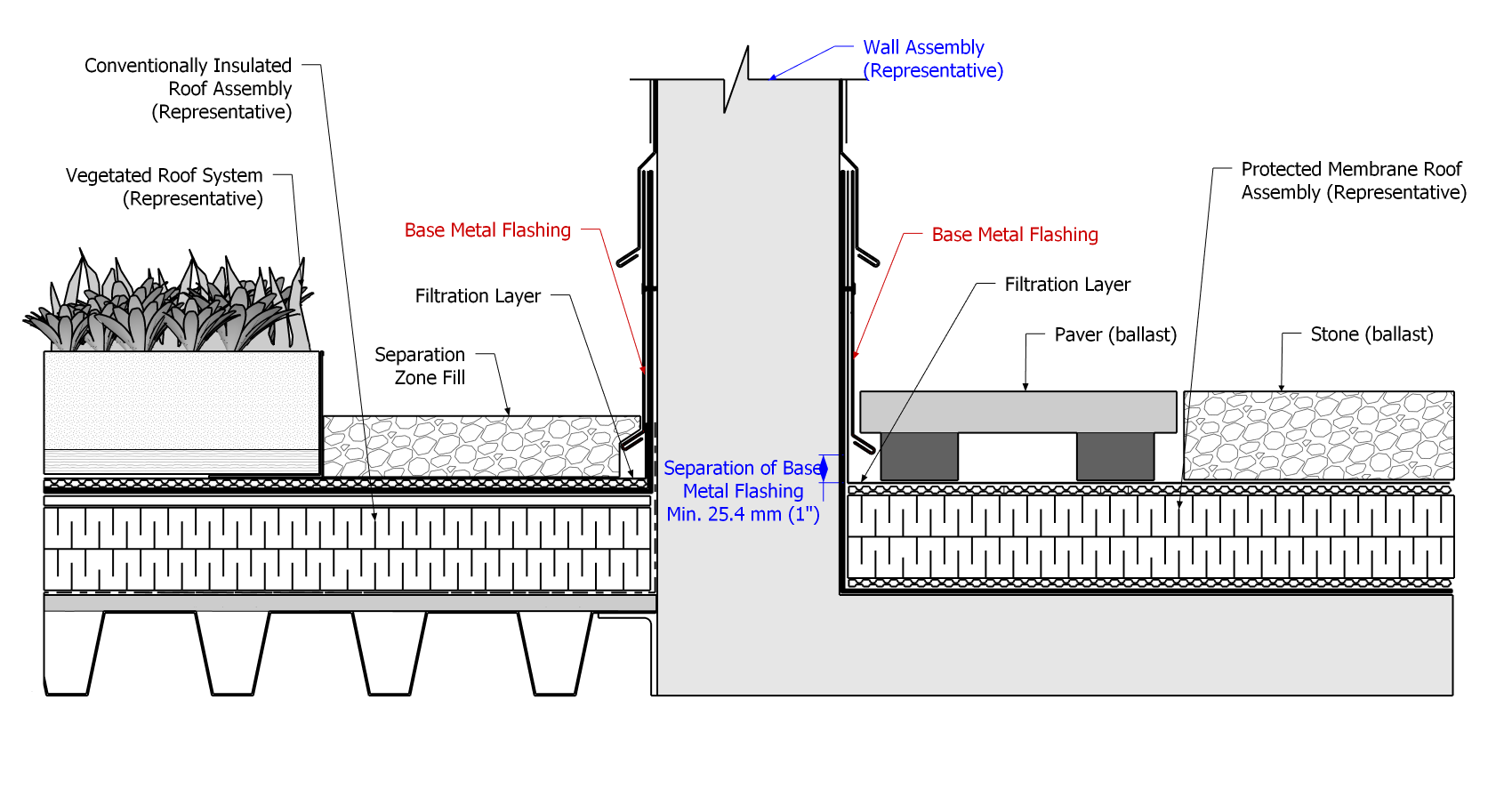
13.3.2.4. Metal Edge Terminations
- Metal edge terminations (including "gravel stop" flashings) are integrated into the membrane system and therefore shall be installed to conform to Article 10.3.4.2.
13.3.2.5. Canted Edges
- Metal flashings on canted edges must be face-fastened on the exterior face of the flashing or, when the height of the canted edge permits, at least 88.9 mm (3-1/2”) above the finished system surface.
- Flashing must be secured with cladding fasteners, evenly spaced between seams along each length of flashing, using no fewer than
- three (3) fasteners for every 3048 mm (120") length of metal flashing, or
- two (2) fasteners for every 2438.4 mm (96") length of metal flashing.
Part 14 - The Roof as a Platform
Section 14.1. Design
(This Part covers the design and installation requirements for roofs that support an overburden, which may be structurally supported or directly supported by the roof assembly)
(See Note A-14.1.)
14.1.1. General
14.1.1.1. Scope
- The scope of this Part and the Standard shall be as described in Division A, Part 1.
14.1.1.2. Defined Terms
- Words that appear in italics are defined in the Glossary. Additionally, the following terms are used in this Part:
- Roof Coverings means (without limitation) gravel, wearing surfaces, Vegetated Roof Systems, pavers, cast-in-place concrete, rubberized surfaces, broadly covering and directly superimposed on the roof assembly.
- Structures and Equipment means structurally supported or portable objects including (without limitation) wood or composite decks and walkways, planters, "amenity spaces" (inclusive of furnishings, hot tubs, gazebos, pergolas, and play areas), nets and wind screens, photovoltaics, satellite equipment, light standards, lightning rods, sculptures, pools, and other water features.
14.1.2. Guarantee Term Requirements
14.1.2.1. RoofStar 5-year Guarantee and RoofStar 10-year Guarantee
- To qualify for a RoofStar 5-year Guarantee or RoofStar 10-year Guarantee, all projects shall comply with the requirements in this Part.
14.1.2.2. RoofStar 15-year Guarantee
- To qualify for a RoofStar 15-year Guarantee, all projects shall comply with the requirements in this Part for a RoofStar 5-year Guarantee or RoofStar 10-year Guarantee.
14.1.2.3. RoofStar Vegetated Roof Guarantee
- To qualify for a RoofStar Vegetated Roof Guarantee, the supporting roof assembly shall
- comply with the requirements in this Part for a RoofStar 5-year Guarantee, RoofStar 10-year Guarantee, or a RoofStar 15-year Guarantee,
- be acceptable to the manufacturer as support for a vegetated roof system, and
- comply with the related requirements in the “RGC Standard for Vegetated Roofs”.
14.1.3. All Systems
14.1.3.1. Coverage and Limitations
- Coverage under the RoofStar Guarantee shall be as described in Division A, Article 3.2.1.2.
14.1.3.2. Loads
- The building structure must be designed to support any live loads specified by the Code having jurisdiction, including loads from any covering, amenity space, structure, or live loads superimposed upon the roof system.
- Roof assemblies
- must be designed as a protected roof system when they cannot support the superimposed loads described above (See also Article 8.1.4.1.).
- must be designed as a protected roof system when the roof covering is
- a semi-intensive vegetated roof system, or
- an intensive vegetated roof system(See Article 1.1.3.2., “RGC Standard for Vegetated Roofs”).
- should be designed as a protected roof system when the roof covering or living (amenity) space
- exceeds 152.4 mm (6”) in depth,
- includes cast-in-place concrete surface,
- is installed over a podium roof area adjacent to residential high-rise structures,
- includes water features or pools, or
- includes expansive terrace areas or play spaces.
- When the superimposed load is a vegetated roof system, the design of the supporting roof assembly shall conform to the requirements in Article 1.1.3.1. and Article 1.1.3.2. of the “RGC Standard for Vegetated Roofs” and shall take into consideration the future loads from a mature, fully saturated vegetated roof.
- Structural supports (i.e., curbs) should be considered to bear heavier dead loads, to resist Specified Wind Loads, or to secure the equipment during seismic events.
14.1.3.3. Securement of Roof Coverings, Structures, and Equipment
- The Design Authority is responsible to specify the appropriate securement design of roof coverings, structures, and equipment, to resist Specified Wind Loads.
- Vegetated roof systems shall be secured in keeping with the requirements of the “RGC Standard for Vegetated Roofs”.
- Where structural securement is desirable or required,
- structural supports must be fully waterproofed (curbs, sleepers, posts) and
- the superimposed structure or equipment must be secured to the structural support at least 203.2 mm (8”) above the drainage plane (See Part 12,"Penetrations and Curbs", and Part 3, "Securing the Roof Assembly").
14.1.3.4. Design for Repairs and Renewal
- Each design should, without limitation, include consideration for
- the inevitability of roof repairs or replacement,
- access for maintenance, and
- material removal, storage, and replacement logistics.
14.1.3.5. Roof Membranes
- Membranes must be selected for their ability to resist accidental puncture by human activity on the roof; the minimum puncture resistance must be at least 400 N (See Table 9.2.1.1. in Article 9.2.1.1.).
14.1.3.6. Membrane Protection
- Membranes must be protected from damage incurred
- during the construction of a building,
- from normal use and occupancy of the roof, and
- from maintenance of any installation on top of a roof system, after the building has been commissioned.
- To prevent accidental damage and puncture from falling objects, conventional insulated systems at elevations lower than those designed for human occupancy should include a protective wearing course or, in the alternative, should be designed as a protected roof system.
- Where membranes installed on vertical surfaces may be damaged from foot traffic or shifting coverings, they must be protected (i.e., with base metal flashing; ref. Article 13.1.3.6.).
14.1.3.7. Membrane Integrity Testing and Electronic Leak Detection
(See Article 1.1.3.3. and Article 1.1.3.4.)
14.1.3.8. Drainage
- Roofs designed as platforms to support roof coverings, amenity spaces, or equipment must promote unimpeded drainage of storm or irrigation water.
- The drainage of a roof assembly supporting a vegetated roof system shall be designed in coordination with the design requirements in the “RGC Standard for Vegetated Roofs”.
- Where a roof covering material naturally drains (i.e., gravel), no additional drainage design is required, but when it does not naturally drain, the design must incorporate a drainage plane on top of the completed roof system.
- Overburden must be contained with drain guards, rigid barriers, and filter fabric (See also Article 11.3.2.3.).
- To facilitate the adequate movement of water and minimize or prevent damming when non-structural supports are oriented perpendicular to (across) the direction of drainage, the design must
- specify shorter supports, to a maximum length of 1219.2 mm (48"), and
- incorporate drainage mats beneath supports longer than 1219.2 mm (48") in any direction.
- Equipment installed on structural supports, or on top of the roof system, must be spaced or located to promote access to drains, ease of maintenance, and worker or occupant safety.
14.1.3.9. Filter Fabric
- Filter fabrics are required when the roof supports
- a vegetated roof system (See Part 6 in the “RGC Standard for Vegetated Roofs”),
- sand and other fine materials,
- gravel with a diameter less than 12.7 mm (1/2”),
- wet mortar or concrete, or
- XPS insulation above the membrane (See Note A-14.1.3.9.).
14.1.3.10. Gravel
(See Note A-14.1.3.10.)
- When smooth stone (aggregate rock) is specified as the roof covering (different from ballast),
- only washed gravel may be used, and
- the design must include gravel guards around roof drains.
- When the gravel used as a roof covering is crushed, or is smaller than 12.7 mm (1/2”),
- a geotextile protection layer must be installed immediately above the roof membrane, and
- the crushed gravel must be deep enough to hold the geotextile protection layer in place.
14.1.3.11. Wearing Surfaces
(See also Article 9.1.3.4. concerning wearing surfaces and drainage requirements)
- Any wearing surface may be installed on an uninsulated or conventionally insulated system, provided
- the compressive strength of the insulation will support it,
- insulation is covered with a suitable overlay (See Article 8.1.4.1.),
- the wearing surface does not bond with or touch the roof field membrane or membrane flashing, and
- drainage of storm or irrigation water is not impeded.
- When a wearing surface is specified,
- it must incorporate measures to protect the roof membrane from damage,
- perimeter membranes and penetrations must be protected from abrasion by the wearing surface,
- the design must provide a drainage space below the wearing surface measuring at least 12.7 mm (1/2”) in depth, and
- the design must provide a vertical drainage gap between the wearing surface and any openings.
- When cast-in-place concrete is specified as the wearing surface (See Note A-14.1.3.11.), the design must conform to the other requirements in this Article, and the concrete must be separated from the membrane with
- a bond-breaking material, such as a proprietary drainage mat or XPS insulation, and
- filter fabric or a barrier material acceptable to the membrane manufacturer, able to prevent the concrete slurry from reaching the membrane.
14.1.3.12. Vegetated Roof Systems
- Vegetated Roof Systems (VRS) must be designed to meet the requirements in the “RGC Standard for Vegetated Roofs”
- this includes membrane protection, drainage, water retention materials, filter fabrics, etc.
14.1.3.13. Structures and Equipment
- Non-structural installations superimposed on a roof assembly
- are recommended for smaller installations, to
- minimize the number of penetrations, curbs, or sleepers necessary for structural securement,
- eliminate possible weak points in the roof system, where a leak may occur,
- avoid dedicated mechanical drainage, and
- simplify removal of materials when membrane repairs are required.
- must take into account inevitable roof renewal (see Note A-14.1.3.13.),
- must be placed on an appropriate protection layer or supported by pedestals, pavers, or other means of distributing weight and point loading, and
- may be placed on an insulated roof system provided the insulation will support all anticipated dead loads, live loads and point loads (See Article 14.1.3.2., "Loads").
- are recommended for smaller installations, to
- Structurally supported installations that are
- cast-in-place must be constructed on a pre‐curb that is continuously waterproofed as part of the primary roof membrane and waterproofed independently of the primary roof membrane.
- pre-cast must be secured
- to a pre‐curb that is continuously waterproofed as a continuation of the primary roof membrane, or
- to structural supports that are waterproofed in keeping with the requirements in Part 12.
- When concrete walls or structures are constructed without a pre-curb, all concrete surfaces must be fully and continuously enveloped with the primary roof membrane (See also Division A, Article 3.2.1.2.).
- Pre‐curbs must be
- at least 101.6 mm (4") in height above the drainage plane of the highest adjacent roof assembly,
- completely enveloped with fully adhered acceptable membrane flashing (including all faces of drainage knock‐outs), and
- properly waterproofed around dowels in their final position, using
- a 2-component catalyzed polymethyl methacrylate (PMMA) or polyurethane methyl methacrylate (PUMA) reinforced liquid membrane flashing system, or
- two cured coats of an Accepted polyurethane or silicon-based single-component liquid flashing system (See Article 12.3.2.6., "Liquid Membrane Flashing").
- When a structural planter adjoins a protected roof system, the planter design must include
- a plumbed mechanical drain , or
- drainage knock-outs in the pre-curb wall, which should be wide enough to allow for the free flow of water over or past of the membrane flashing plies.
- When a structural planter adjoins an insulated roof system, only a plumbed mechanical drain is permissible.
- A design review is advisable when a structural water feature incorporates penetrations for wiring, lights, or other submerged features.
- Tiles or other architectural finishes may be applied to the waterproofing membrane, subject to a written Variance from the Guarantor and approval by the membrane manufacturer (See Article 1.1.3.6., "Variances").
- Drains, re-circulation inlets, and outlets used in water features, must include clamping rings, and must be sealed to the membrane assembly.
- When a leak detection system is specified, only non‐ferrous metal drains may be used.
Section 14.2. Materials
14.2.1. Material Properties
14.2.1.1. Field and Flashing Membranes
- Refer to Table 9.2.1.1. in Article 9.2.1.1. for field membrane composition, thickness, and selection.
- Single and 2-component liquid membrane flashing systems used on any detail, including pre-curbs, must be listed in Division C, and must be proprietary to, or accepted by, the manufacturer.
14.2.1.2. Membrane Protection
- Membranes must be protected from damage by installing (directly above the roof membrane)
- drainage mat,
- an asphaltic core board overlay, measuring at least 4.76 mm (1/8”) thick,
- XPS insulation, measuring at least 25.4 mm (1”) thick, or
- a geotextile protection layer with a minimum thickness/weight of 200 g/m2 (used in vegetated roof system applications, where decorative gravel is crushed or smaller than 12.7 mm (1/2”) in diameter, or where the roof covering, superimposed structure or equipment does not exceed the load-bearing capacity of the protection material).
14.2.1.3. Reserved
14.2.1.4. Drainage and Water Retention Materials
- Drainage mats, geo-synthetic drainage cores, and geo-composites used beneath any non-vegetated overburden, must be
- acceptable to the manufacturer,
- suitable for the installed roof covering,
- selected for their ability to support dead loads, live loads, and point loads, and
- capable of permitting the anticipated flow rate of water.
- Moisture retention and reservoir layers must be acceptable to the manufacturer/supplier of the Vegetated Roof System.
14.2.1.5. Insulation and Insulation Overlays
(See Part 7, "Insulation", and Part 8, "Insulation Overlays")
- When XPS (with or without a concrete topping) is specified as the drainage layer, it must be grooved (by the manufacturer, or as a post-manufacturing alteration).
- Insulation and insulation overlays must have a minimum load carrying capacity of 110 Kpa (20 psi), but in any event must be capable of supporting any loads superimposed on the membrane, without compression or distortion of the roof system or any one of its components.
14.2.1.6. Filter Fabric
- Filter fabrics must be
- acceptable to the manufacturer,
- suitable for the installed roof covering,
- selected for their ability to support dead loads, live loads, and point loads, and
- capable of permitting the anticipated flow rate of water.
- The properties, composition, and supply of filtration fabrics used in a vegetated roof system shall conform to the requirements in Article 6.2.1.2. of the “RGC Standard for Vegetated Roofs”.
- Fabric filter mats must be
- water permeable and have proven long term weather resistance, and
- strong enough to withstand traffic abuse and prevent displacement of insulation boards under flotation conditions.
14.2.1.7. Decorative Gravel
- Decorative gravel (aggregate) (See Note A-14.1.3.10.) must be washed and may be smooth or crushed.
- Large grade gravel may withstand wind scour more effectively than smaller gravel, but the Design Authority must determine the gradients, based on the Specified Wind Loads for the roof (See also Article 3.2.2.3., Gravel Ballast).
14.2.1.8. Pavers and Pedestals
- Pavers that are partially supported (i.e., with pedestals) must be capable of resisting anticipated loads.
- Pedestals
- should be adjustable when a level surface is required, and
- must be purpose-made and include an integral spacer rib no more than 4.76 mm (1/8”) wide, to uniformly separate pavers.
Section 14.3. Application
14.3.1. Guarantee Term Requirements
14.3.1.1. RoofStar 5-year Guarantee and RoofStar 10-year Guarantee
- To qualify for a RoofStar 5-year Guarantee or RoofStar 10-year Guarantee, all projects shall comply with the requirements in this Part.
14.3.1.2. RoofStar 15-year Guarantee
- To qualify for a RoofStar 15-year Guarantee, all projects shall comply with the requirements in this Part for a RoofStar 5-year Guarantee or RoofStar 10-year Guarantee.
14.3.2. All Systems
14.3.2.1. Membranes and Membrane Protection
- Membranes and membrane flashing must be installed in keeping with the requirements found elsewhere in this Standard.
- Protection of roof membranes from mechanical damage caused by tools, accident or the work of others is mandatory during the installation and maintenance of any roof covering or living space (See also Article 9.1.3.4., "Membrane Protection", for related requirements).
14.3.2.2. Filter Fabric
- Fabric filter rolls used in any system other than a vegetated roof system must be
- at least 2489.2 mm (98") wide,
- installed loose-laid (un-bonded) over the insulation and below any type of ballast or roof covering,
- overlapped at all edges a minimum of 304.8 mm (12"),
- slit to fit over roof penetrations,
- cut out around roof drains and other openings,
- carried up all vertical transitions (including penetration flashings) above the finished system surface at least 76.2 mm (3”), and
- loosely held in place at all perimeter edges and curbs, behind metal counter flashings or wall finishes, and
- secured around penetration flashings.
14.3.2.3. Drainage
- The location of the drainage layer(s) shall conform to the requirements in Part 7.
- A second drainage layer may be installed above the insulation, but this is at the discretion of the Design Authority.
- Specialized proprietary drainage products must be acceptable to the manufacturer.
14.3.2.4. Decorative Gravel
- When gravel (aggregate) is specified as a roof covering, only washed gravel may be used.
- Ballast guards must be installed around all roof drains (See Article 11.3.2.3.).
- Crushed gravel specified as a roof covering must be
- installed over a geotextile protection layer, or its equivalent, when the gravel is crushed or smaller than 12.7 mm (1/2”) in diameter, and
- must be applied in quantities sufficient to hold down the protection layer against displacement by wind.
14.3.2.5. Wearing Surfaces
- Pavers and unit-type masonry, such as brick or stone, must be supported by
- proprietary (purpose-made) pedestals with at least a 4.76 mm (1/8”) integral spacer ribs for uniform spacing of pavers,
- a proprietary drainage layer overlaid with a filter fabric mat, or
- a drainage layer of loose aggregate (such as pea gravel) measuring at least 25.4 mm (1") in depth, installed over a filter fabric.
- Pedestals, or a drainage layer,
- must permit at least 12.7 mm (1/2″) of vertical separation between the paver and the underlying substrate, to provide airflow for drying surfaces and assist in leveling, and
- should not impede the flow of water or air, and should uniformly distribute the dead load of pavers, and other unit masonry products, as well as predicted live loads.
- Cast-in-place concrete installed directly above the roof membrane must be separated from the membrane and its protection layers with material and a filter fabric or barrier material specified by the Design Authority and conforming to the requirements in Article 14.1.3.11.
14.3.2.6. Vegetated Roof Systems
(See Note A-14.3.2.6.)
- All Vegetated Roof Systems must be installed according to the requirements in the “RGC Standard for Vegetated Roofs”.
14.3.2.7. Structures and Equipment
- Structural installations (i.e., planters, pools, ponds, or water courses) must be constructed with
- a pre‐curb (start‐up curb), onto which the installation is formed and poured, or
- full-height walls that are formed and poured in direct contact with the structural deck.
- Pre‐curbs (Figure 14.3.2.7.-A) must
- achieve a finished height at least 101.6 mm (4") above the drainage plane of the highest adjacent roof assembly (For an example of this see Construction Detail "Structural Planter"), and
- be completely enveloped with fully adhered acceptable sheet or liquid membrane flashing (including all faces of drainage knock‐outs).
- All planters and water features must be fully waterproofed on the inside; sheet membrane installation must conform to the requirements in Article 10.3.2.3., and liquid membrane flashing shall conform to the requirements in Article 10.3.3.4.
- All membrane flashing shall terminate
- on the outside face of the planter wall, at least 50.8 mm (2”) below the upper edge, or
- on the inside face of the planter wall with a cut reglet linear metal flashing, caulked with sealant and installed no less than 50.8 mm (2”) above the top surface of growing media.
- Structural installations that do not incorporate pre-curbs must be
- flashed to cover the complete exterior surface with roof membrane, or
- flashed with sheet membrane that is installed, terminated, and protected to conform to Article 10.3.2.3.
Figure 14.3.2.7.-A Pre-curbs and Sheet Membrane Flashing
Forming Part of Article 14.3.2.7.
(Click to expand illustration)
- Dowels (reinforcement bar) must be
- inserted into the pre‐curb after application of the membrane flashing, and
- waterproofed in their final position, where they penetrate the pre-curb.
- Dowels must be waterproofed with
- a single application of an accepted, fleece-reinforced 2-component liquid membrane flashing, or
- two (2) applications of a single-component liquid membrane flashing,
- applied to properly prepared surfaces,
- fully cured between coats,
- in keeping with the application requirements in Article 10.3.3.4., for 2-component reinforced liquid membrane flashing, or the manufacturer’s instructions, when using a single-component liquid membrane flashing, and
- applied no less than 50.8 mm (2”) on vertical surfaces and in a radius around the base of each dowel.
- When structures or equipment exceed the limits stated in Division A, Article 3.2.1.2., a membrane integrity scan and any resulting repairs must be undertaken before the membrane is covered.
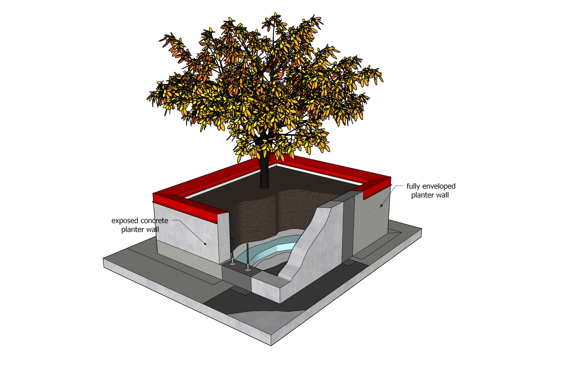
Notes to Standard
© RCABC 2026
RoofStarTM is a registered Trademark of the RCABC.
No reproduction of this material, in whole or in part, is lawful without the expressed permission of the RCABC Guarantee Corp.