
SBS Plumbing Vent (Conventional Roof System)
SBS Plumbing Vent (Conventional Roof System)
Division D - Construction Details
SBS | Plumbing Vent (Conventional Roof System) ( Article 12.3.2.1.)
| Notice to Reader | |
| Images used in a Construction Detail are representative and not prescriptive, and are not necessarily drawn to scale. They are intended to support the related Standard (Ref. Division A, Article 2.2.1.2.).
The reader may link to the related Article in the detail title, or link to the Standard as it relates to a specific element in the detail. All hyperlinks are displayed blue text. | |
SBS Details
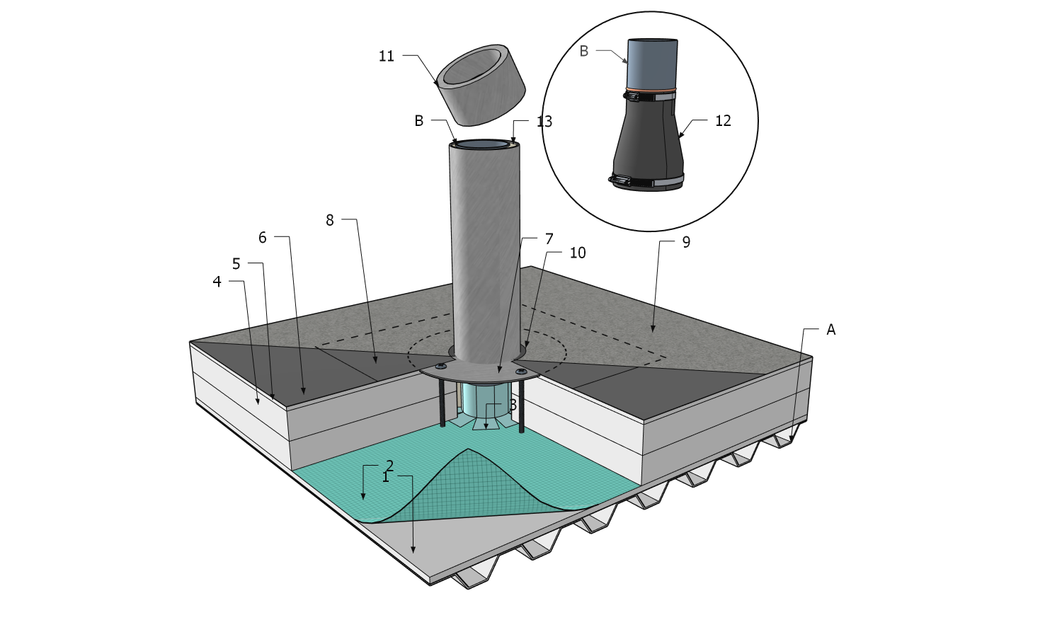
1 WORK INCLUDED
- (1) Supporting Deck Overlay
- If specified and included in a Tested Assembly, an Assembly with Proven Past Performance, or a custom-engineered assembly.
- (2) Air or Vapour Control Layers
- As required by Design Authority.
- (3) Air or Vapour Control Layer Tie-in
- Illustrated to show AVB continuity with penetration.
- (4) Insulation
- Multiple layering shown (Refer to Part 7 for design, material, and installation requirements).
- (5) Insulation Overlay
- As required by the RGC Standard; see Part 8 for design, material, and installation requirements. Additionally, an overlay is required is included in a Tested Assembly, an Assembly with Proven Past Performance, or a custom-engineered assembly.
- (6) Field Base Sheet Membrane
- Selected to conform to the requirements in Table 9.2.1.1. and conforming to the options or requirements in a Tested Assembly, an Assembly with Proven Past Performance, or a custom-engineered assembly.
- (7) Penetration Flashing
- Purpose-made non-ferrous plumbing vent flashing with separate settlement cap (Item 11), sized to fit the penetration, bedded in a membrane-compatible mastic, and installed with screw fasteners. Aluminum flashings are required for torch-applied roof systems.
- (8) Membrane Target Patch
- Sized to extend at least 101.6 mm (4”) past the edge of the penetration flashing flange and sealed to the field membrane and primed flange.
- (9) Field Cap Sheet Membrane
- Selected to conform to the requirements in Membrane Composition, Thickness, and Selection Table 9.2.1.1. and conforming to the options or requirements in a Tested Assembly, an Assembly with Proven Past Performance, or a custom-engineered assembly.
- (10) Mastic
- Applied to edge of membrane and immediately covered with granules (not shown).
- (11) Settlement Cap
- Sized to fit both inside the penetration pipe (to direct rainwater into the penetration) and outside the flashing (a snug fit, secured with a screw, is required to keep the cap in place).
Optional: Vandal-proof cap (not shown).
- (12) EPDM Membrane Wrap (Optional)
- Used when the plumbing pipe cannot be cut down to fit inside the flashing (Refer to Article 12.3.2.1., Sentence (16)).
- (13) Flashing Insulation
- Factory-applied for insulated flashings, used where condensation between the pipe and the flashing is possible.
2 RELATED WORK BY OTHERS
- (A) Supporting (Structural) Roof Deck
- Steel deck illustrated.
- (B) Plumbing Penetration
- Extend to match top of metal flashing.
NOTE: See the Standard for additional requirements.
Back to "SBS" Roof System Details
© RCABC 2025
RoofStarTM is a registered Trademark of the RCABC.
No reproduction of this material, in whole or in part, is lawful without the expressed permission of the RCABC Guarantee Corp.