SBS Roof Systems Standard
SBS Roof Systems Standard
Contents
- 1 GENERAL REQUIREMENTS
- 2 ROOF DECKS
- 3 WIND UPLIFT DESIGN and CSA A123.21
- 4 MATERIALS
- 5 SUBSTRATES: Deck Overlay Board and Wall Sheathing
- 6 AIR & VAPOUR BARRIERS
- 7 INSULATION
- 8 INSULATION OVERLAY BOARD
- 9 MEMBRANES
- 10 VEGETATED ROOF ASSEMBLIES, PLANTERS & OCCUPIED SPACES
- 11 PERIMETER & DETAIL FLASHING: Membranes
- 11.1 General
- 11.2 Material Selection
- 11.3 Application
- 12 ROOF PENETRATIONS and DRAINS
- 13 PERIMETER FLASHING: Metal
- 14 OTHER DETAILS
This section contains the Standards, Guiding Principles, Recommendations and reference materials necessary for the design and installation of a roof qualifying for a RoofStar Guarantee.
All relevant Standards for the selection and application of materials necessary to qualify for a RoofStar Guarantee are found in this section. Readers are advised to review relevant materials that can be accessed through the links available in the body of text or embedded in section titles; these are shown in blue font. Subsection titles shown in blue indicate links to more relevant material that the reader is advised to consult.
Content in this section is colour-coded according to four classes:
- Guarantee Standards
- Guiding Principles
- Recommendations
- Reference materials
To hide or reveal classes of text, use the buttons at the bottom of the page. Guarantee Standards always remain visible
For definitions of these terms of reference, click here.
1 GENERAL REQUIREMENTS
NOTE: See also Low-slope Membranes for additional application notes and cautions.
1.1 Roof Slope
All new construction roofs must have positive slope to drain.
In re-roof projects, crickets and saddles should be provided to assist drainage.
For single-ply SBS roof systems, a minimum slope 1:15 (3/4" in 12")is required. Any roof areas less than 1:15 (3/4" in 12") require 2 ply membrane assemblies.
A minimum slope of 1:50 (l/4" in 12") is strongly recommended, and should provide positive slope to drain (positive slope to drain is required for a RoofStar 5-Year Roofing Guarantee or RoofStar 10-Year Roofing Guarantee for new construction). Positive slope to drain is attained when no standing water remains on the deck within a reasonable amount of time after rainfall stops during days with conditions that permit evaporation.
Slope can be provided by sloping the deck, or using tapered insulation boards of insulating fill (insulating fill is rarely used in B.C.). Drain wells that are designed to collect water and provide a flat surface for the installation of roof drains do not require a slope. Therefore standing water may remain in drain wells for a longer period after a rainfall stops.
Crickets and saddles should be employed between drains where the design slope of the roof is less than 1:50 (1/4" in 12"), where the roof deck is uneven and ponding may occur, or simply to assist the movement of water to drains.
In re-roof applications, when utilizing 2 ply modified asphalt membranes, there is no requirement for slope to drain. However, slope is strongly recommended.
1.2 Quality Control
As with all flexible membranes, the quality of the installation is critical to the performance of bituminous and modified bituminous membranes. Although some of the application techniques for these membranes can be similar to those employed in built-up roofing, and the materials can be “familiar”, the differences are critical. It is important that the specifications, details, and installation techniques all conform to the membrane manufacturer's requirements.
One of the major concerns when applying these membranes with hot asphalt is to ensure the asphalt remains hot enough to fuse with the binder of the membrane. The asphalt temperature must conform to the membrane manufacturer's minimum application temperature and minimum +205°C (+400°F) as required by RoofStar Guarantee Standards. Install modified bituminous membrane systems with conventional Type 3 or 4 oxidized asphalt or Type 3 or 4 SEBS modified asphalt (see also 9 MEMBRANES). Asphalt should not be mopped more than 1 m (3') preceding the roll as it has been demonstrated that the temperature of mopped asphalt drops sharply once mopped out (read more in Built-up Roofing (BUR) Materials). In addition to asphalt temperature, particular attention should be paid to slope limitations, fastening requirements, type of asphalt, the amount of asphalt used, and membrane flashing requirements when using hot asphalt. Some manufacturers may require "torched" membrane flashing to ensure a proper bond and prevent problems with slippage or asphalt running down the vertical and collecting at the cant. Slippage can also be a problem when an excessive amount of asphalt is used. Only enough asphalt to meet the adhesive requirements is needed. The mopping asphalt has a lower softening point than the bitumen in the membrane and may result in asphalt running and slippage problems.
1.2.1 Torch-applied Membrane Systems
The major concern when installing "torch-on" membranes is an obvious one: SAFETY. This is discussed in detail in the SBS Application section of this Manual. In addition to safety, it is essential that the membrane be fully and evenly bonded to the substrate. As the roll is installed, the roofer must ensure the full width of the roll is melted and the preceding roll's side lap is preheated. A small "wave" or "bead" of melted bitumen in front of the roll usually indicates sufficient heat. Special attention to seams is required.
The polyester fabric used as reinforcing in many thermofusible "torch-on" membranes is subject to dimensional changes at high temperatures. Care must be exercised by the applicator not to over-torch or over-heat membranes. Membranes must be designed and manufactured specifically for torch applications. It is recommended that the cap sheet installation immediately follow base sheet installation in all cases. However, when it may be necessary to delay the installation of the cap sheet due to weather, project scheduling or the like, then the following criteria must be considered:
ANY delay in the installation of a cap sheet will result in the requirement for a special inspection and thorough cleaning of the base sheet. The inspection is for mechanical damage from traffic or trades and cleaning is necessary to ensure good adhesion; this must be done to the satisfaction of the roofing contractor.
Base sheets which are either sanded, glaze coated or thermofusible can be exposed for up to six months. It must be recognized that an exposed base sheet is vulnerable to mechanical damage and construction dirt. The base sheet should be well protected by carefully placed and maintained protection panels (plywood for example). This protection would be supplied, installed and removed by someone other than the roofing contractor.
Consult manufacturer(s) for specific construction details and specifications.
1.2.2 Cold-applied Membrane Systems
See 8.3.6 Cold-applied (Adhered) Membranes.
1.2.3 Hot-mopped Membrane Systems
The design authority should recognize that the appearance of wrinkling and ridging in modified bitumen cap sheets applied in hot asphalt may be generic to certain manufacturers of this system, and particularly when attempted in cooler temperatures. Although some manufacturers' literature suggests application may take place in temperatures as low as -25°C (-13°F), there are many subsequent limitations, the variables of which may result occasionally in severe wrinkling or ridging of the cap sheet as well as potentially poor adhesion.
The RoofStar Guarantee Program recommends that, in order to minimize the potential for wrinkling and ridging, the use of mopped cap sheets not be considered or specified when ambient temperatures (including wind chill) may go below +5°C (+41°F).
Many factors affect the behaviour of the finished prefabricated sheets including:
- The quality of the binder (waterproofing agent).
- The choice of carrier including suppliers of fibreglass, polyester, or a combination of the two.
- Saturation of the carrier.
- Engineering of the sheet (composition and placement of the components within the sheet).
- Quality control of the manufacturer.
- Expertise of the manufacturer's personnel (including field representation).
- Recommendations as to what is required for a completed system and the recommended application procedure.
- Installation in the field by a competent contractor.
- The designer's role in choosing the product(s) which satisfy each previous item described.
The wrinkles or ridges are usually considered an aesthetic problem only, but may occasionally result in fishmouthing and intermittent bonding of the cap sheet. Both of these deficiencies affect the performance of the membrane.
The RoofStar Guarantee Program recommends the use of torch applied thermofusible cap sheets in 2-ply modified bitumen systems in all cases, but particularly if roofing must be carried out in cool or cold weather. Appropriate safety precautions regarding torching must be addressed.
NOTE: Occasionally some mopped systems, particularly with heavy cap sheets, have exhibited a propensity for membrane slippage, frequently on insulated systems where there is a combination of slope, heavy inter-ply mopping and lack of mechanical fastening (back nailing) of sheets. See 8.3.4 "Mechanically Attached" membranes for requirements and slope limitations.
It is also common for mopped systems to exhibit some asphalt bleed-out at the seams. Minimal or reasonable bleed-out is to be expected and is an aesthetic problem which may be minimized by the embedment of matching granules. Bleed-out which oxidizes and alligators with time does not normally affect the waterproofing efficiency of the roof.
1.3 Re-covering or Retrofitting
Retrofitting over existing membrane is permitted only in specific circumstances and only when approved in writing by the RoofStar Guarantee Program (Technical Manager) and the membrane manufacturer.
For RoofStar Guarantee Standards' pertaining to wind uplift resistance, refer to Wind Uplift Design and CSA A123.21 below.
1.4 Tying Into Existing Roofing
Where a new roof is tied-in to an existing roof, the two areas must be isolated and separated by a curb joint properly attached to the structure and properly flashed. If job conditions do not allow for a curb joint, written permission must be obtained from the RoofStar Guarantee Program (Technical Manager) to eliminate curb joints. Where a curb joint is eliminated with consent from the RoofStar Guarantee Program, a positive water cut-off must be installed to the deck to isolate the existing roof from the new roof.
2 ROOF DECKS
| NOTE: See more information on Roof Decks in Section B: Essential Elements. |
2.1 General
The roof deck must be designed to serve two major functions:
- As a structural component to transfer the weight of live and dead loads to supporting members. Live loads include construction equipment and workers, rain, snow, and ice. Dead loads include the deck itself, the roofing system, HVAC units and, possibly, landscaping. Most decks must also act as a diaphragm, transmitting wind or seismic lateral forces to the buildings structural framework.
- As a suitable substrate to which the roof membrane or roof system is attached.
Prior to the application of the roof system, the deck must be smooth, straight, and free of "humps" or depressions. These can counteract any sloped insulation systems installed by the roofing contractor and cause ponding. On new construction projects, this is usually provided by the general contractor with review by the design authority and/or the building authority having jurisdiction.
The use of EPDM membranes in loose laid ballasted or loose laid protected membrane assemblies over concrete decks is not permitted unless a membrane underlay (recommended in writing by the membrane manufacturer) is installed.
In addition, the roof deck must comply with several guiding principles, to be acceptable for a RoofStar Guarantee:
- For low slope (membrane roof or waterproofing systems) it should provide positive slope to drain (required for a RoofStar 5-Year Roofing Guarantee, RoofStar 10-Year Roofing Guarantee, or a RoofStar 5-Year Waterproofing Guarantee for new construction and for organic felt membrane systems when re-roofing). Positive slope to drain is attained when no standing water remains on the deck within a reasonable amount of time after rainfall stops during days with conditions that permit evaporation. Where required, crickets and saddles should be provided to assist drainage. Slope can be provided by sloping the deck, or using tapered insulation boards or insulating fill (insulating fill is rarely used in B.C.). Tapered slope insulation products can only be used to provide slope if any differences from level in the roof deck are less than the percentage of slope provided by the insulation. A minimum slope of 1:50 (1/4" in 12") is strongly recommended. The exception is often drain wells that are designed to collect water and provide a flat surface for the installation of roof drains. Therefore, standing water may remain in drain wells for a longer period of time after a rainfall stops.
- It should be dimensionally stable and capable of accommodating roof system component movement.
Deck deflections should be limited to 1/240 of the total span, but must conform to the Building Code. For plywood decks, the RoofStar Guarantee Program Standards limit the allowable deck deflection to 1/360 of the total span to prevent differential edge movement. Concentrated, non-uniform construction loads should be considered during design. Drains should be located at points of maximum deflection whenever possible, not over columns or bearing walls. Building settlement can often cause slopes to change and low spots to appear on the roof surface.
Prior to the commencement of roofing, any curbs, cants and blocking that are to be installed by others, should be in place.
2.2 Deck Types
2.2.1 Wood Decks
Wood is a common construction material that has been used for many years because of its economy, ease of fabrication, lighter construction, and ready availability. Acceptable wood roof decks may include wood board decks, plywood decks, and, subject to restrictions, non-veneered wood decks (oriented strand board, waferboard, etc.). All types of wood decks should be roofed promptly after installation.
All wood decks shall be properly fastened to BC Building Code requirements. With the exception of standard insulated roof systems, all knots or cracks shall be covered with metal prior to acceptance of deck surface. This work is to be done by others. Non-veneer (O.S.B. or wafer board) panels are acceptable sheathing for decks with low-slope roofing applications, provided the roofing membrane is not fully adhered directly to the panels. The minimum plywood or non-veneer (O.S.B or wafer board) deck thickness for low-slope roofing (i.e., membrane roofing) shall be a minimum 12.7 mm (½") and as indicated in the applicable Building Code.
All types of wood decks should be roofed promptly after installation.
Differential edge movements or deflection in excess of 1/360 of the span in plywood or non-veneer decks in low slope roofing must be prevented by:
- solid blocking under non-supported edges, and /or
- use of tongue-and-groove plywood with non-grooved edges supported by joists or solid blocking, and / or
- when rigid insulation is over the deck, properly sized and installed H-clips must be used on the unsupported edges.
2.2.1.1 Wood Board Decks
Wood board decks include tongue-and-groove, shiplapped, or splined boards or planks usually ranging from 19 mm to 89 mm (nominal 1" to 4") thickness. Also 38 mm (nominal 2") by various width boards, placed on end, can be spiked together to form a “mill deck”. The thickness of the boards is determined by the anticipated loads and spacing of roof joists or trusses (consult Building Code).
Wood board decks should be of sound seasoned lumber, properly secured to supporting structure. The deck should form a firm smooth surface, free from knotholes, cracks, projections, depressions and other defects. Prior to the roofing contractor's acceptance of the deck, minor knotholes and cracks should be covered with securely nailed sheet metal (performed by others).
Wood board decks, especially mill decks, often have so many surface defects that a plywood overlay is desirable (9.5 mm (⅜") plywood is often acceptable). Where a plywood overlay is not required, a mechanically fastened base sheet or separator sheet is required for built-up roofs or fully-adhered bituminous or modified bituminous flexible roofing membranes. For non-bituminous flexible membranes (elastomeric or plastomeric membranes such as EPDM or PVC), a slip sheet or separator sheet should be installed according to membrane manufacturer's recommendations. Separation sheets, slip sheets, and mechanically fastened base sheets are installed to help relieve stresses in the membrane due to movement of the deck.
2.2.1.2 Plywood Decks
Plywood roof decks consist of exterior type plywood mechanically fastened to the roof framing. The plywood panels should conform to CSA 0121, “Douglas Fir Plywood”, CSA 0151, “Canadian Softwood Plywood”, or CSA 0153, “Poplar Plywood”, as per Building Code requirements.
These thickness / span ratios will minimize deck deflection, especially with construction loads, and will provide a better surface for nailing as the bouncing effect of thin plywood’s is reduced.
For low slope roofing (e.g. BUR), plywood must be minimum 12.7 mm (1/2") thick unless mechanically attached rigid insulation is installed prior to the roofing membrane. The minimum centres for supporting members are:
- 400 mm (16") for 12.7 mm (1/2") plywood sheathing
- 600 mm (24") for 15.9 mm (5/8") plywood sheathing
For low-slope roofing, differential edge movement and deflection in excess of 1/360 of the span must be prevented by:
- solid blocking under non-supported edges, and / or
- use of tongue-and-groove plywood with non-grooved edges supported by joists or solid blocking, and / or
- when rigid insulation is over the deck, properly sized and installed H-clips should be used on the unsupported edges.
Plywood roof sheathing should be installed with the surface grain at right angles to the roof framing, with end joints staggered.
Plywood decks receiving roofing directly applied to the deck should be attached using wood screws or nails which are especially resistant to pull-out or nail popping, particularly when using a single-ply membrane (i.e., use ring-type or ardox; smooth common nails are not acceptable). Nail popping is usually caused by a combination of thermal and structural movement and is especially critical where the membrane is directly adhered to the deck. All fasteners should have a corrosion-resistant coating (such as galvanizing). The structural suitability of the fastener is the responsibility of the design authority.
2.2.1.3 Non-veneer Wood Decks
Non-veneer panels are identified as waferboard or oriented strand board (OSB) panels, as opposed to plywood or veneered panels.
Non-veneer (O.S.B. or waferboard) panels are acceptable decks on low-slope roofing applications when an approved separation sheet or rigid insulation is mechanically attached before fully adhered roofing membrane is applied.
2.2.2 Concrete Decks
Concrete roof decks include decks that are cast-in-place or pre-cast, and structural or non-structural in nature. Although this roof deck category includes numerous variations (discussed later), many of the precautions involved with roofing over them are similar.
The finished surface of the deck should be smooth, level, and free of moisture or frost. All ridges or projections should be removed; and curbs, cants, blocking, and nailing strips should be installed where required prior to the roofing contractor's acceptance of the deck. With cast-in-place decks, special care must be taken to ensure that the deck is cured for 28 days and that the surface is dry. (A simple test for determining whether the deck is dry enough for roofing is to apply hot asphalt to the deck; if it foams or is easily peeled off after it cools, the deck is too wet.) Pre-cast decks may require joints to be “taped” or stripped-in with felts, and the joints, weld plates, and elevation differences to be feathered with grout.
Concrete decks, curbs and equipment pads must be clean, dry, and smooth prior to commencement of roofing.
Poured concrete or lightweight concrete decks are not to be roofed for a minimum of 28 days after pouring unless expressly instructed in writing by the Project Structural Engineer.
Although some concrete decks are considered “nailable”, insulation is most commonly attached by using proprietary adhesives, or by applying hot asphalt over a primed deck. In the latter case, the asphalt is mopped to the deck and allowed to cool to the point where the insulation is not melted, but is still sufficiently bonded to the deck.
Built-up roof membranes can be directly adhered to both cast-in-place decks and, provided precautions are taken, to pre-cast decks. Vented base sheets may be used to provide semi-adherence to the roof deck.
Concrete roof decks include:
- Cast-in-place reinforced concrete
- Pre-cast concrete panels
- Pre-stressed concrete
- Lightweight insulating concrete
Poured gypsum concrete
A cast-in-place reinforced concrete roof deck is produced by pouring concrete into formwork containing reinforcing steel bars or welded steel mesh. The surface of deck should be screeded and trowelled to provide a smooth, level surface. Caution should be exercised when using certain curing agents and techniques. Curing agents may not be compatible with roofing materials and some curing techniques do not allow the deck to dry sufficiently.
Pre-cast concrete-panel roof decks consist of manufactured panels designed to span between beams or load-bearing walls. They are available in the following cross-sectional shapes: single “T”, double “T”, solid slabs, hollow-core slabs, inverted channels, and tongue-and-groove planks. Metal plates may be installed to provide a welded structural connection and lateral bracing.
Pre-stressed concrete roof decks consist of concrete (usually pre-cast panels) that is pre-stressed using integral steel tendon reinforcement. The unit is compressed to counteract flexural tensile stresses which usually result in a cambered unit (a slight curve that results in the centre of the unit being higher than the supporting ends). The camber will usually flatten once the structure is loaded.
Lightweight insulating concrete roof decks and fills consist of concrete mixtures that have vermiculite or perlite as insulating aggregates, or they may also be produced by mixing pre-generated foam with Portland cement and water. This type of deck is usually designed for application over steel decks, corrugated metal forms, or bulb-tee or formboard systems. The concrete mixture is placed and screeded on site. Usually these mixes use a very high water / cement ratio and may require a lengthy cure time and a vented base sheet because of high moisture content. Vented base sheets provide a path for moisture vapour to vent to an appropriate point where the vapour may be released.
Poured gypsum concrete roof decks consist of a mixture of gypsum concrete, wood fibres or mineral aggregate, and water. The mixture is poured into formboards that contain welded or woven galvanized wire fabric. The formboards are left in place and may provide the finished interior surface.
2.2.3 Steel Decks
Steel roof decks are constructed of light gauge (usually 22, 20, or 18 gauge) cold-rolled steel sections (panels) that are usually galvanized. In cross-section the panels are ribbed, with the ribs usually spaced at 150 mm (6") on centre. The ribs provide the strength and rigidity of the panels. Steel decks are generally supported by open-web steel joist framing and are welded or mechanically-fastened to the framework. Steel deck panels must be properly aligned, squarely intersect walls, and provide a smooth level surface for roofing.
For insulated roof assemblies, a thermal barrier may be required to conform with Building Code or fire insurance-rated assemblies. This is usually required where the insulation is classified as combustible. Uninsulated systems require a leveling underlay for the membrane. Gypsum board may serve both purposes (thermal barrier & level surface).
Minimum thickness of insulations should be checked carefully to ensure that the material can safely span the flutes. The insulation or insulation overlay must be mechanically-fastened to the deck, unless it is a ballasted system.
Corrosion Protection For New Steel Roof Decks
When steel roof decks are specified, the RoofStar Guarantee Program recommends that the design authority specify the decking be factory-galvanized or factory-coated with aluminum zinc alloy for corrosion protection.
When specifying galvanized protection (in the section of the specifications addressing metal decking), the design authority should specify a coating that complies with ASTM A 525 Class G-60 or Class G-90. A G-90 coating provides greater corrosion protection than a G-60 coating (the ASTM specification previously identified G-60 as “light commercial” and G-90 as “commercial”).
When specifying aluminium zinc alloy protection (in the section of the specification addressing metal decking), the design authority should specify a coating that complies with ASTM A 792. An aluminum zinc alloy coating provides greater corrosion protection than a G-90 galvanized coating.
NOTE: The above recommendation applies to most buildings. However, in highly corrosive or chemical atmospheres, special care in specifying protective finishes should be taken, and individual deck manufacturers should be contacted.
2.3 Roof Expansion Joints
(See Construction Details to view the illustrated application of RoofStar Guarantee Standards for various membrane assemblies)
Roof expansion joints are designed to prevent membrane splitting and ridging (caused by either movement of the building, or movement of the roof assembly due to thermal expansion and contraction).
Roof expansion joints should be considered wherever:
- the type of deck changes
- additions connect to existing buildings
- expansion and control joints exist in the structural system
- separate wings of a building join (e.g. “L” or “T” configurations)
- interior heating conditions change
differential movement may occur (e.g. parapet detail where the deck is not supported by the wall)
The location of roof expansion joints must be clearly indicated on the drawings and in the specifications, as the installation of wood blocking and cants is the responsibility of “others” and must be in place prior to the roofing contractor's acceptance of the deck.
2.4 Roof Divider / Control Joints
(See Construction Details to view the illustrated application of RoofStar Guarantee Standards for various membrane assemblies)
Roof dividers (sometimes referred to as control joints or area dividers) are built on-site. They are designed to help control thermal expansion and contraction stresses in the roof system where no structural expansion joint has been provided in the building design. Roof dividers are especially useful for controlling stress concentration in the membrane, and should be considered (and may be required) on all fully-adhered roof membrane systems.
A roof divider is usually designed as two raised wood members attached to a wood base-plate that is securely anchored to the roof deck and then properly flashed with membrane and metal. Roof dividers should divide the roof into approximately equal, regularly-shaped areas. Ideally, roof dividers should be located at the high points of the roof, with drainage away from the divider on both sides, but DRAINAGE MUST NOT BE IMPEDED BY THE ROOF DIVIDER.
RoofStar Guarantee Standards for a RoofStar 5-Year Roofing Guarantee or RoofStar 10-Year Roofing Guarantee for built-up roof membrane requires roof dividers / control joints “to divide roofs into areas approximately 45 m x 45 m (150' x 150'), at changes of deck material and decking direction, at re-entrant corners, and at junctions or additions to existing structure.
The location of roof dividers must be clearly indicated on the drawings and in the specifications, as the installation of wood blocking and cants is the responsibility of others and must be in place prior to the roofing contractor's acceptance of the deck.
NOTE that the requirement for roof divider / control joints for flexible membranes differs, and must be evaluated on a product performance basis.
2.5 Special Circumstances: Electrical Conduit
Conduit, EMT, cable and/or piping applied on the top of roof deck surfaces shall not be acceptable on new construction projects.
If conduit is present on decks in re-roofing projects, the deck must be made smooth and even to the satisfaction of the accepted roof inspection firm. The upper layer of insulation must cover the conduit, EMT, cable and/or piping. Detailed as-built drawings should be made to prevent conduit damage and safety risks to roofers, should the roof require replacement at a future date.
For more about this topic, see the published Safety Bulletin in the November 10, 2015 Technical Update.
3 WIND UPLIFT DESIGN and CSA A123.21
Template:Wind Uplift Design and CSA A123.21
4 MATERIALS
| NOTE: Click here to view all the Materials accepted for use in the RoofStar Guarantee Program. |
All roofing components must be supplied or accepted by the membrane manufacturer and must be acceptable to the RoofStar Guarantee Program. A listing is published in this manual (see link above).
All materials must be protected from weather by properly stacking above ground or roof surface and in factory packaging or other adequate covering, approved or recommended by the manufacturer, until applied. All installed roofing materials that are susceptible to moisture damage must be made watertight by the end of each work day.
5 SUBSTRATES: Deck Overlay Board and Wall Sheathing
| NOTE: See more information on Roof Deck Overlay Boards in Section B: Essential Elements. |
5.1 General
5.2 Material Selection
Regardless of the substrate to which roof membranes are applied, installation of roof membrane to the surface must be governed by the membrane manufacturer's requirements for that substrate.
Gypsum boards on vertical surfaces must be a RoofStar-accepted overlay boards with water resistant properties.
On steel framed walls, it is acceptable to use gypsum overlay boards accepted for the RoofStar Guarantee Program, provided the gypsum board has a minimum thickness of 12 mm (½") or fibre-mat reinforced cement boards with a minimum thickness of 9.5 mm (⅜") that conform to ASTM C1325-04.
See Accepted Deck Overlay Boards for RoofStar Guaranteed roof systems.
5.3 Application: Decks
5.3.1 Concrete
- Concrete decks, curbs and equipment pads must be clean, dry, and smooth prior to commencement of roofing.
- Poured concrete or lightweight concrete decks are not to be roofed for a minimum of 28 days after pouring unless expressly instructed in writing by the Project Structural Engineer.
- All concrete decks to receive adhered asphaltic roofing shall be primed.
- A vented base sheet is required under all asphalt-adhered (adhesive, mopped or torched) roofing membranes that are adhered directly to concrete decks unless insulation is installed directly above or over the membrane.
Pre-cast panels, post-stressed beams, or “T” and cavity decks must have a separation layer such as fibreboard, gypsum board, plywood, proprietary overlay board etc. applied over the deck prior to the application of the roof membrane. Where a difference exists in the levels of adjacent surfaces, the general contractor or others shall install grouting. This grouting shall be feathered on the lower surface a minimum distance of twelve times the amount of the vertical differential.
5.3.2 Steel
1. When a membrane is specified for application directly over a steel deck, the RoofStar Guarantee Standards require a steel deck overlay of gypsum with fibreglass facers and a silicone treated gypsum core (see min. standards below), or plywood having a minimum thickness of 12.7 mm (½"). Where an underlay is used as a thermal barrier, it must conform to the applicable code and insurance requirements for the roof assembly and be fully supported by the deck.
2. Gypsum boards installed over steel decks as substrates for primary roof membranes must be a minimum thickness of 12.7 mm (½") RoofStar-accepted overlay boards. All edges of the gypsum board are to be fully or intermittently supported by the deck and end joints to be staggered (offset) 300 mm (12") from adjacent board rows. A minus offset tolerance of 50 mm (2") maximum will be permitted to compensate for variance in the manufacturer's tolerance of differing board widths and lengths.
3. When gypsum board is required on steel decks as a substrate overlay, the gypsum board can be fully mechanically fastened to the deck or adhered with proprietary polyurethane foam adhesives acceptable to the primary roof system manufacturer. Attachment must meet or exceed the CSA A123.21-14 requirements for the building dimensions and geographical location.
Maximum deck flute width and minimum fastener requirements for gypsum board in a deck overlay application are as follows:
| Thickness | Deck Flute Width | Board Size | Screws & Metal Stress Plates | Bulgle-head Drywall Screws |
|---|---|---|---|---|
| 12.7 mm (½") | up to 125 mm (5") | 1200 mm x 2400 mm (4' x 8’) | 12 | 32 |
| 15.9 mm (5/8") | up to 200mm (8") | 1200 mm x 2400 mm (4’ x 8’) | 12 | 32 |
4. When gypsum board is used under mechanically fastened insulation, the gypsum board must be fastened independently from the insulation. The minimum number of fasteners(screws or screws and plate) is four (4) per sheet. When applicable, adhesive systems must meet or exceed the CSA A123.21 requirements (current edition) for the building dimensions and geographical location.
5.3.3 Wood
1. An RoofStar-approved separation sheet, minimum 40-lb asphalt coated fibre glass base sheet conforming to CAN/ CSA A123.16 - M88 (R1996), Type II or manufacturer’s accepted base sheet of equal or greater weight and reinforcement, or RoofStar-accepted rigid insulation / overlay board mechanically attached or semi-adhered membrane (spot or strips) is required over non-veneer panels before fully adhered roofing membrane is applied.
2. Direct torch (open flame) membrane applications to wood decks and wood surfaces is NOT permitted. For further development of this policy, refer to Best Practices in SBS Special Applications
3. Fully adhering modified bituminous membranes directly to wood decks is not permitted.
5.4 Application: Wall Sheathing
5.4.1 Walls Supporting Roof Deck
In combustible construction, or where permitted by the Building Code in non-combustible construction, all concrete or masonry parapets or walls which do not provide a smooth, clean, dry surface for membrane adhesion or are to be applied with oxidized asphalt as the adhesive must be sheathed with a minimum 15.9 mm (5/8") treated plywood, or 9.5 mm (3/8") reinforced cement board that conforms to ASTM C1325-04 mechanically attached to the wall. The plywood is to extend either a minimum of 200 mm (8") above membrane surfacing, to the bottom of the reglet, or, if required by the type of membrane, to the full height of the parapet.
5.4.2 Non-Supporting Walls
Where permitted by the Building Code, all concrete or masonry parapets or walls to which roofing is to be applied must be sheathed with minimum 15.9 mm (5/8") plywood or 9.5 mm (3/8") reinforced cement board that conforms to ASTM C1325-04 solidly attached to the roof deck with adequately treated blocking. Compressible insulation is to be installed between the sheathing and the wall. Coping and / or counter flashing is to be installed. See Detail: D1.7.4 for an illustration. The plywood is to extend either a minimum of 200 mm (8") above membrane surfacing or, if required by the type of membrane, to the full height of the parapet or wall. This item is supplied and installed by others unless specified otherwise.
Gypsum boards on vertical surfaces must be RoofStar-accepted overlay boards with water resistant properties. On steel framed walls accepted gypsum overlay boards with a minimum thickness of 12mm (1/2") or fibre-mat reinforced cement boards with a minimum thickness of 9.5 mm (3/8") that conform to ASTM C1325-04 are an acceptable vertical substrate to receive roofing.
The installation of roof membrane to the surface must be as per the membrane manufacturer's requirements for that substrate.
6 AIR & VAPOUR BARRIERS
| NOTE: See more information on Air and Vapour Control in Section B: Essential Elements. |
6.1 Intent
Air and vapour barriers, along with thermal barriers, water resistive barriers and water-shedding surfaces, serve to separate the outside environment from the interior environments of a structure. Continuous air barriers are perhaps the most critical. Building Codes in force in each jurisdiction, and the National Energy Code (2011), require the selection and proper installation of “a continuous air barrier system comprised of air-barrier assemblies to control air leakage into and out of the conditioned space” (NEC 2011).
Continuity of the air and/or vapour barrier from the wall systems and roof systems is essential to the satisfactory performance of either or both. Therefore, proper connection between air and/or vapour barrier systems is essential, and the responsibility of both the design authority and trades constructing walls and roofs.
Air barriers control “flow of air through the building enclosure, either inward or outward” (Guide for Designing Energy Efficient Building Enclosures, Homeowner Protection Office). Controlling air flow into and out of conditioned spaces affects the performance of “thermally efficient enclosure assemblies” (ibid), impacts the potential for condensation in between materials, and directly influences rain water penetration of the building envelope. Some air barriers are considered permeable, others air-impermeable or ‘airtight’. The suitability of one over the other, in the application of a roofing system, is left to the discernment of the design authority and/or the roofing contractor. Consequently, the RoofStar Guarantee Program strongly recommends that designers and builders of roof systems intended to qualify for a RoofStar Guarantee carefully consider the regulatory design and installation requirements for effective, continuous air barrier systems.
Vapour barriers regulate or prohibit the movement of water vapour from one space to another by means of diffusion. Consequently, these barriers are referred to as either vapour-permeable or impermeable. Diffusion is a slow process, in contrast to air movement, and its regulation is not always mandatory or even desirable. Consequently, because continuous vapour barriers “are not needed within all climate zones and assemblies”, they are considered non-critical and may be left to the discretion of the design authority. Nevertheless, where continuous vapour barriers are required and specified by provincial or municipal building codes (current and in force), the RoofStar Guarantee Program requires that a suitable vapour barrier system be selected by the design authority and properly installed by the roofing contractor in conformity with the vapour barrier manufacturer’s published instructions, and with the design authority’s specified details.
Any references in this Manual to installation methodologies, and any construction details that show air and/or vapour barriers, are merely illustrative and not prescriptive. Installers of continuous air and/or vapour barrier systems are urged to understand and comply with best practices for their application.
6.2 Limitations and Exclusions
Air and vapour barrier performance is not part of the RoofStar Guarantee, and air/vapour barrier materials are not listed in the Accepted Materials section of this Manual. Therefore, the decision to specify an air and/or vapour barrier, the placement of a continuous air and/or vapour barrier in relation to a roof assembly and system, and the selection of suitable materials for that application, is the sole responsibility of the design authority.The design authority is urged to review and consider the performance characteristics of materials available for such applications.
Neither the RoofStar Guarantee Program nor the roofing contractor will accept any responsibility for damage to, or failure of, the roof system caused by the use or absence of air and/or vapour barriers.
Proper installation and continuity of air and/or vapour barriers within the roof assembly is the responsibility of the roofing contractor. The air/vapour barrier must:
- extend past the roof membrane flashing by 100mm (4”) on new construction providing a positive (water-shedding) lap seal union between courses of material for the wall air/vapour barrier membrane applicator.
- be sealed to the wall air/vapour barrier on roof replacement projects.
- Installation must conform to the manufacturer’s published requirements and the design authority’s design details.
6.3 Material Selection
Fully supported air and/or vapour barriers must possess a minimum published static puncture resistance rating of 150 N (34 lbf) (ref. CGSB-37.56-M for both test method and standard limits) and be either self-adhering or torch-applied. For unsupported air and/or vapour barriers, see 4.3.3 below. Therefore, while responsibility for the selection of a suitable air/vapour barrier rests with the design authority, a roof designed and built to qualify for a RoofStar Guarantee shall not include either polyethylene sheet plastic or bitumen-impregnated kraft paper.
Where air and/or vapour barriers are specified by the design authority, they must be selected from the materials listed in the wind-tested assemblies reports for MARS, PARS or AARS roof systems (excluding polyethylene sheet plastic and kraft paper, as noted above). For a complete listing of current wind test reports, click on the linked system acronyms above.
Notwithstanding any of the foregoing, the RoofStar Guarantee Program strongly recommends that any air and/or vapour barrier system be installed over a smooth, continuous plane (for example, concrete or plywood). Consequently, a deck overlay board installed on corrugated steel roof decks in highly recommended. Where no deck overlay board is installed and the air and/or vapour barrier is partially unsupported (for example, on a steel deck), the air and/or vapour barrier must have a published static puncture resistance of at least 400 N (90 lbf). Furthermore, both the side laps and end laps must be fully supported.
Should the air/vapour barrier membrane be used as a temporary roof during project construction by either the roofing contractor or by other trades, a minimum 2mm thick bituminous membrane is recommended.
Because curing concrete releases considerable moisture that can compromise the performance of a roof system, a vapour barrier installed on new concrete decks (28 days or older) must be selected to prevent condensation inside the roof system. A membrane with a permeability of 0.01 perms (Class I) is recommended. Nevertheless, the selection of the vapour barrier product is the responsibility of the design authority.
6.4 Vapour Retarder Design for High-Humidity Building Interiors
Careful consideration should be given to the performance characteristics of air and/or vapour barriers when specifying such a membrane for roof assemblies constructed over high-humidity building interiors. These types of building interiors include (but are not limited to)
- Swimming pools
- Commercial laundry facilities
- Large aquariums
Paper mills
Roof systems for facilities such as these, with high-humidity environments, may be susceptible to the accumulation of moisture within the roof assembly unless an effective vapour barrier is specified and installed.
Vapour retarders for high humidity facilities should have a perm rating as close to zero as possible, be durable, multi-layer membranes that are effective in preventing vapour drive into the roof systems from the interior of high humidity environments.
Thin, lightweight, single-layer vapour retarders are prone to damage during installation of roof assemblies and are therefore not recommended for use over high humidity building interiors.
7 INSULATION
| NOTE: See more information on Roof Insulation in Section B: Essential Elements. |
7.1 General
- Only RoofStar-accepted insulation, specifically listed by membrane manufacturers in the RPM as acceptable for use with their modified bituminous loose laid, or mechanically attached base sheets, may be used without an overlay board in the RoofStar Guarantee Program.
- When heat-sensitive insulations are used in a roof assembly, they must be covered with a heat-resistant insulation at least 50 mm (2") thick.
7.2 Material Selection
See Accepted Roof Insulation products for RoofStar Guaranteed roof systems.
7.2.1 Polyisocyanurate Insulation
Only polyisocyanurate insulation with non-organic facers(e.g. fibreglass) are acceptable for use in the RoofStar Guarantee Program. In addition, manufacturers’ product identification labels are required for all Polyisocyanurate insulation packaging and the date of manufacture must be provided on all product labels.
See also Storage and Handling notes under the Polyisocyanurate section of Insulating the Roof, in this Manual.
7.2.2 Mineral Wool Insulation
Mineral wool insulation panels must be fastened or adhered according to the manufacturer’s published instructions and tested assemblies, but in any event must conform to the options shown in the table below.
- Permissible Conventional Roof Assembly - Mineral Wool Insulation
A Non-Coated Mineral Wool Base Insulation layer is permissible only by mechanically fastening, but may not have additional insulation layers adhered to it.
†† NOTE: All conventional roof systems with an overburden (see 10.1.1 & 10.1.2)require a ½” cover board over the top layer of insulation, regardless of its type. Adhere cover board only if top insulation layer is bitumen-coated.
7.3 Application
- The edges of insulation boards should be square, flush and have moderate contact with the edges of adjacent insulation boards. End joints between adjacent insulation boards must be staggered.
- On steel roof decks, deck flutes and felts should normally run in parallel alignment and be perpendicular to the roof slope. Insulation boards should be firmly supported by steel deck flanges. When only one layer of insulation is installed, the long dimension of insulation boards should not cantilever over steel deck flutes.
- For heat sensitive insulation and heat insensitive foamed insulation, RoofStar Guarantee Standards should be consulted for fibreboard overlay requirements for Five (5) or Ten (10) RoofStar Guarantee requirements.
The specifier should not simply reference the thermal performance for a roof assembly by specifying the total R-value. The generic type, thickness, C-value, and applicable standards of the insulation required for application should also be specified.
7.3.1 Layering
A staggered double-layer insulation system may provide the following benefits:
- elimination of thermal bridges, where leakage of heating or cooling energy may occur.
- reduced ridging, by eliminating through-joint migration of moisture vapour into the membrane, and subsequent deformation.
reduced ridging and splitting in the roof membrane.
All square edge flat format insulation boards greater than 67.5mm (2.7”) in thickness shall be installed in multiple layers. With the exception of systems that include tapered insulation, individual layers are not to exceed 60% of total insulation/overlay board assembly. Multi layering of plastic foam insulation is required for all adhered, mechanically attached, and ballasted low slope roof assemblies. In addition, all slope format plastic foam insulation boards greater than 150mm (6”) in thickness shall be installed in multiple staggered layers or alternatively, be installed under two (2) offset/staggered layers of RoofStar-accepted insulation overlay boards.
Insulation board joints are to be offset or staggered 300 mm (12") from adjacent layers and rows.
A minus offset tolerance of 50 mm (2") maximum will be permitted to compensate for variance in manufactured tolerance of differing insulation board widths and lengths. The exception is sloped insulation boards that are generally installed soldiered fashion to adjacent rows; and the first layer of overlay board over heat sensitive insulation to facilitate joint taping. However, the uppermost layer of insulation or overlay board directly below membranes shall have joints that are offset/staggered from adjacent layers and rows.
- utilize self-adhering seams for flame protection,
- are mechanically attached over decks listed by the membrane manufacturer, and
- are specifically accepted by the RoofStar Guarantee Program
7.3.2 Nailing Strips
Required on Slopes exceeding 1:12 (1" in 12"):
Where the total insulation thickness on nailable decks exceeds 25 mm (1"), nailing strips shall be mandatory on all insulated exposed membrane roofs utilizing asphalt-based adhesives (cold or hot-applied) and will be supplied and installed by the roofing contractor. These nailers should be nominal 89 mm (3- 1/2") wide and of a thickness equal to that of the primary insulation. Spacing of these nailers will not exceed four feet for horizontal application and two feet for vertical application.Fasteners for attachment of wood nailers shall be two minimum #12 non-corrosive exterior screws spaced a maximum of 400mm (16”) o/c. Attachment screws shall be embedded into support media a minimum of 37.7mm (1.5”) at all nailing strip fastening points. Nailers are to be covered by one layer of accepted overlay board. Fasteners used for attaching membranes to nailing strips(back nailing) shall be membrane manufacturer’s approved screws with plates or nails with a minimum 25 mm (1") head size. Spacing of fasteners or nails on nailing strips shall not exceed 300 mm (12") o/c for horizontal applications and 600 mm (24") o/c for vertical applications. Where deck nailing strips are required to secure roofing nailing or insulation nailing strips (e.g. in concrete decks), deck nailing strips shall be supplied and installed by others.
Consult the membrane manufacturer's published data for slope limitations.
Nailing strips are not required for use on RoofStar-accepted in-seam mechanically-fastened bituminous or non-bituminous flexible membrane systems. Heat welded or self-adhered SBS modified bituminous systems may be used without nailing strips provided RoofStar-accepted in seam fastener patterns are used throughout all base sheet seams (minimum 24" o/c) and head laps (minimum of 3 fasteners). All layers of insulation are recommended be additionally secured with polyurethane foam adhesive.
7.3.3 Mechanical Fastening
Fastener requirements are not the same for all deck materials. As plywood thickness and steel gauge increases, fastener pull-out strength increases, hence fewer fasteners are required.
7.3.3.1 General
When conventionally adhered roof assemblies are installed, (adhered, hot asphalt mopped, torched, etc.), all insulation must be mechanically fastened to all nailable decks including steel, unless stated otherwise in this Manual. The upper layer or overlay in a multiple-layer insulation application does not require mechanical fastening. The exception is for slopes exceeding 1:12 (1" in 12") or steeper - in those cases, the upper layer must be fastened.
Cavity deck or T Deck may be defined as either nailable or non-nailable, depending on profile and deflection.
Acceptable nail types: Shank-and-head or head-plate nails with minimum 25 mm (1") nominal head size. Head-plate nails with solidly attached plate to ensure plate cannot slide down on shank.
When using multiple layers of plastic foam insulation the layers shall be mechanically fastened, whenever possible, as if they are a single layer. Alternately, when the use of mechanical fasteners is not feasible, or multiple layered assemblies require mechanical fastening of the base layer only, or decks are constructed of non-nailable materials (concrete,) polyurethane foam adhesives may be utilized to adhere insulation layers to one another, to other insulations, or substrates. Only polyurethane foam adhesives that are specifically listed as acceptable by the insulation manufacturer may be used. Extruded polystyrene insulation must have planed faces (removal of smooth surface) when adhered with polyurethane foam adhesive.
The upper layer or overlay in a multiple-layer insulation application does not require mechanical fastening. If mechanical fastening to concrete decking is required proprietary concrete fasteners and plates must be used.
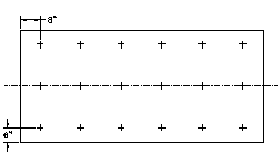
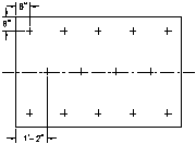
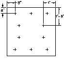
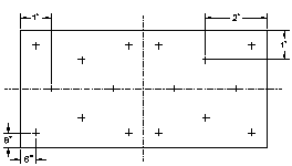
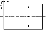
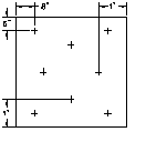
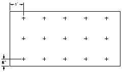
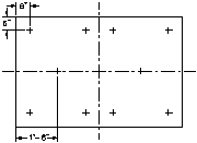
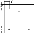
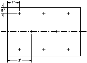
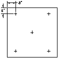
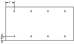
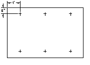
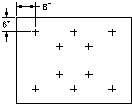
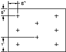
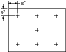
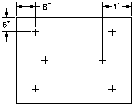
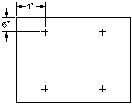
When insulation and or cover boards are installed under mechanically fastened membrane systems the membrane manufacturer’s tested and approved fastener layout patterns shall be followed. In addition, the minimum number of fasteners with plates for insulation and or cover boards, under mechanically fastened membranes, shall be six (6) fasteners for 1200mm x 2400mm (4ft. x 8ft,) board sizes and four (4) fasteners for all other smaller board sizes:
| Insulation Board Size | Field | Perimeter | Corner |
|---|---|---|---|
| 600 mm x 1200 mm (2'x4') | 4 | 4 | 5 |
| 600 mm x 2400 mm (2'x8') | 5 | 6 | 8 |
| 900 mm x 1200 mm (3'x4') | 4 | 6 | 7 |
| 1200 mm x 1200 mm (4'x4') | 5 | 6 | 8 |
| 1200 mm x 1800 mm (4'x6') | 6 | 8 | 12 |
| 1200 mm x 2400 mm (4'x8') | 8 | 12 | 15 |
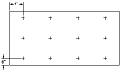
- NOTE: Fastener locations are for optimum uplift resistance. Fasteners may be located within 50 mm (2") of position shown in diagrams in any direction.
| 1' x 2' | 3' x 5' |
|---|---|
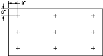 9 Fasteners 9 Fasteners |
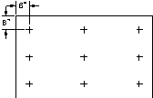 9 Fasteners 9 Fasteners
|
- NOTE: Fastener locations are for optimum uplift resistance. Fasteners may be located within 50 mm (2") of position shown in diagrams in any direction.
7.3.3.2 Heat Insensitive Insulation
In the case of heat insensitive insulation, one layer of acceptable overlay board is required. For hot asphalt applied roof assemblies the insulation is to be mechanically fastened before an acceptable overlay board is fully mopped to the insulation. Alternatively, manufacturers' proprietary insulation adhesives may be used to adhere accepted overlay boards to insulation. When hot asphalt or adhesives are not used in a roof assembly accepted insulation and overlay board(s) may, as a group, be mechanically fastened directly to nailable decks including steel.
7.3.3.3 Application to Steel Decks
The following procedures for installing insulation in roof systems should be followed:
- On steel roof decks, deck flutes and felts should normally run in parallel alignment and be perpendicular to the roof slope.
On steel roof decks, insulation boards should be firmly supported by steel deck flanges. When only one layer of insulation is installed, the long dimension of insulation boards should not cantilever over steel deck flutes.
When installing insulation or thermal barriers to steel decks, all edges of the first layer of insulation or thermal barrier shall be fully or intermittently supported by the deck. Mechanical fasteners must penetrate steel decks a minimum of 20mm (3/4") and must be located in the top flutes only. Adhesive systems must be tested to meet or exceed the CSA A123.21-14 requirements and designed for the building dimensions and geographical location.
The minimum thickness of insulation directly over fluted steel decks shall be a minimum of one-half the nominal flute width. Additionally, the minimum allowable thickness of expanded polystyrene or unfaced glass fibre insulation shall be 38 mm (1-1/2"), and the minimum thickness for extruded polystyrene, faced glass fibre, faced polyisocyanurate, etc. shall be 25 mm (1").(For loose laid ballasted systems, see Ballast Requirements for PMA Roofs)
7.3.3.4 Application to Wood Decks
Nailing is permitted on wood decks only where insulation thickness does not exceed 50 mm (2"). Nails with a minimum 25 mm (1") head size or greater are required for insulation and overlay boards fastened to wood decks. Nails to be placed a maximum 600 mm (24") o/c in each direction and be of sufficient length to penetrate the underlying sheathing a minimum of 20 mm (3/4") or in the case of plywood, completely through the sheathing.
| Insulation Board Size | Field | Perimeter | Corner |
|---|---|---|---|
| 600 mm x 1200 mm (2'x4') | 5 | 5 | 6 |
| 600 mm x 2400 mm (2'x8') | 8 | 10 | 12 |
| 900 mm x 1200 mm (3'x4') | 6 | 8 | 10 |
| 1200 mm x 1200 mm (4'x4') | 6 | 8 | 10 |
| 1200 mm x 1800 mm (4'x6') | 8 | 10 | 14 |
| 1200 mm x 2400 mm (4'x8') | 12 | 16 | 18 |
7.3.4 Adhering Insulation
When foam plastic insulation is adhered (with hot asphalt or compatible adhesive) in a roof assembly, the insulation board size shall be a maximum 1200 mm (4') in any direction.
Only RoofStar-accepted overlay boards may be installed by the back mop and flop application method over heat sensitive foam plastic insulation boards. Heat insensitive insulation boards, (e.g. Polyisocyanurate) are not permitted to be installed with this method.
Asphalt or paraffin-impregnated coated fibreboard roof insulation, used as an insulation overlay board must be asphalt-coated on the top and bottom surface (minimum coated two-sides) when adhered (in a roof assembly) with hot asphalt or asphaltic based adhesive.
When applicable, proprietary adhesive applied insulation/overlay board membrane systems accepted and installed in the RoofStar Guarantee Program shall conform to the CSA A123.2 Standard test method (latest edition) for the dynamic wind uplift resistance of adhesive attached membrane roofing systems.
The roof system must be as per the complete tested assembly and a calculation for the building wind load requirements using the Wind-RCI calculator, as applicable be submitted with project documents.
8 INSULATION OVERLAY BOARD
| NOTE: See more information on Insulation Overlay Boards Essential Elements. |
8.1 General
RoofStar-accepted insulation overlay boards shall be installed over all plastic foam insulations (EPS, XEPS, Polyisocyanurate) on all adhered low slope roofing systems. When heat sensitive insulations (EPS,XEPS) are used with heat welded membrane seams an accepted overlay board must be installed. Overlay board thickness shall not exceed 50mm (2″). Fibreboard shall not be used with flame-welded seams.
8.2 Layering
Insulation and overlay board joints are to be offset/staggered 300 mm (12") from adjacent layers and rows. The uppermost layer of [insulation or] overlay board directly below membranes shall have joints that are offset/staggered from adjacent layers and rows.
See also RoofStar Guarantee Standards for insulation layering in INSULATION
8.3 Material Selection
See Accepted Insulation Overlay boards for RoofStar Guaranteed roof systems.
8.4 Application
8.4.1 Mechanical Fastening
The design authority should research and establish the correct fastener, deck and roof assembly components in order to prevent the possibility of fastener corrosion. Contributing factors to fastener corrosion may include dissimilar metal contact, excessive building humidity, corrosive chemicals within components of the assembly, or corrosive elements provided within the building envelope etc.
All insulation types shall have a minimum compressive strength of 110 KPa (20 psi) when installed without a cover board under mechanically attached membranes.
Mechanical fastening to steel decks provides more effective wind uplift resistance and greater horizontal shear resistance than adhesives (thereby decreasing potential membrane splitting). Fastening patterns and rates that have proven to be successful are published in RoofStar Guarantee Standards and should be enforced as a minimum. In addition to insufficient fasteners, the type of fastener can prove critical. For example, failure may occur from nails with inadequate head size to pull through the roofing felts.
The correct fastener should be specified by the design authority for each component of a roof system.
The design authority should consult with the fastener manufacturer to determine the fastener's pullout strength in specific deck types to determine the number of fasteners required.
Wind uplift has been shown to be greater at the perimeters and therefore fastener requirements vary between field and perimeter areas. In addition, mechanical fastening may be required at the perimeter detail to restrain lateral movement of the membrane.
The upper layer or overlay in a multiple-layer insulation application does not require mechanical fastening.
| Using | Field | Perimeter | Corner |
|---|---|---|---|
| Screws and Plastic or Steel Stress Plates | 8 | 12 | 15 |
| Accepted Nails (Wood Deck Only) | 12 | 16 | 18 |
| Fastener layout patterns and other board dimensions | See diagrams above |
8.4.2 Adhering
When asphaltic membranes are adhered (using hot asphalt, cold adhesives, or when applied with a torch), at least one layer of overlay board is required over all types of insulation. The exception to this requirement is mineral wool insulation used in a single or multi-layered adhered or partially adhered insulation assembly, where the top surface of the uppermost insulation layer incorporates an impregnated bitumen surface to which an asphaltic membrane may be torch welded, mop-applied or cold-adhered.
Conventionally insulated roof assemblies are required to have a minimum 12.5mm (½") adhered approved RoofStar-accepted gypsum overlay board, and insulation boards with a minimum compressive strength of 20 psi, under the roof membrane for Extensive Vegetated Systems (less than 150 mm, 6" in depth). Intensive Vegetative Roof Assemblies in excess of 150 mm (6") or more in depth are not permitted over conventionally insulated roof systems.
Note the following restrictions and conditions, which apply to the above:
- flame protection may be required where only one layer of insulation is specified.
- where mineral wool insulation is mechanically fastened through the uppermost insulation layer, an adhered non-flammable cover board with a thickness of no less than 12.5 mm (1/2”) is mandatory, to prevent fastener penetration of the adhered membrane. A cover board is not required where only the bottom layer of a multi-layer mineral wool insulation assembly is mechanically fastened.
The following standards, principles and information also apply:
Heat Sensitive Insulation: On all heat sensitive insulation (polystyrene - both extruded and expanded), an overlay consisting of two layers of acceptable cover board (each with min. 3/16" thickness) is to be used when using hot-applied adhesive, when torch-welding or where the cover board is less than 1/2" in thickness on torch-applied assemblies. Overlay board thickness shall not exceed 50 mm (2”). Fibreboard shall not be used with flame-welded membrane seams.
- A. Single layer system: When insulation is installed as a single layer, flame protection over the cover board is required. Install the insulation and cover board with the proprietary accepted adhesive. Seal over all board joints and wall transitions with membrane manufacturer's approved self-adhered membrane tape.
- B. Two layer system: When using a hot-applied adhesive, back mop and flop first layer of overlay board, or use manufacturer's accepted proprietary adhesives per published directions, offsetting the joints from those of the insulation. Tape the joints before applying the second layer, offsetting the joints from both layers below.
Alternatively, the membrane manufacturer's proprietary insulation adhesives may be used to adhere accepted cover boards and insulation.
RoofStar-accepted mechanically attached asphalt core overlay boards [minimum thickness 4.5 mm (3/16") nominal] or insulation and insulation overlay boards specifically designed for torch applications, must be attached with nails with a minimum 25 mm (1") nominal head size placed a minimum of one nail per 0.093 m² (1 sq. ft.) or plates and screws placed a minimum of 0.186 m² (2 sq. ft.). Seal all board joints and wall transitions with membrane manufacturer’s approved self-adhered membrane or tapes.
8.4.3 Joint Taping
Acceptable materials for taping joints, of hot asphalt, and cold adhesive applied roof assemblies on overlay board, insulation, gypsum board, and primed plywood are minimum 150 mm (6") wide No.15 felt, 150 mm (6") wide Fibreglass roof tape, or 150 mm (6") wide sheathing (membrane breather-type to CAN / CGSB 51.32-M77). The only acceptable methods of hot asphalt installation are by back coating with asphalt, or laying with a back-coating machine expressly intended for the purpose.
9 MEMBRANES
| NOTE: See more information on Low-slope Membranes Essential Elements. |
9.1 General
While the roof is being applied, all membrane openings at eaves, walls, vents, etc. must be sealed to prevent moisture from entering roofing or between plies of stripping.
NOTE: Fully nailed base sheet and torched cap sheet is considered a single-ply for Guarantee purposes.
Both the base sheet and cap sheet in 2-Ply modified bituminous systems must be of modified bitumen materials using the same polymer. For example, if the cap sheet is an SBS modified bitumen sheet, then the base sheet must be an SBS modified bitumen sheet. Oxidized asphalt sheets will be considered as underlay only and must not be counted as one of two plies.
Both the base sheet and cap sheet must be installed in a parallel direction (not at 90° to each other).
For the application of 2-ply ungranulated membranes; both the cap sheet and base sheet are to be applied separately. Shingle fashion application (i.e., 50% lap) is not acceptable except where membrane back nailing is required.
All modified bitumen base stripping terminating on vertical surfaces must be mechanically fastened.
9.1.1 Slope Limitations
Only factory cap sheets are to be used on slopes exceeding 1:24 (1/2" in 12"). Manufacturers published instructions as to application methods, materials, and slope limitations are to be followed. On slopes less than 1:24 (1/2" in 12"), double pour, modified double pour or alternate modified double pour and gravel surfacing may be used.
9.1.2 Membrane Lap Preparation
- Manufacturer's printed instructions for overlaps are to be followed.
- Granules are to be embedded prior to forming laps on all torch applied modified bituminous cap sheets.
- Membrane end lap corners must be cut on a bias (clipped or trimmed on an angle) prior to forming laps on all torch applied modified bituminous membrane roof systems.
9.2 Material Selection
See Accepted SBS Membranes for RoofStar Guaranteed roof systems. See also Section 3 for special requirements concerning Membrane Roof Systems.
Not all membranes are ideal or even acceptable for every type of application. Below is a table that outlines the new minimum thickness and puncture resistance requirements for SBS-modified bituminous membranes, based on what type of assembly they will be used in (effective for projects bid after March 1, 2018):
| 2-Ply SBS Modified Roof Membranes: Field & Membrane Flashing Membrane Application Method |
SBS Cap Sheet under Vegetated Assemblies |
Single-Ply SBS Cap Sheet for Slopes >3/4:12 |
SBS Waterproofing Membranes | ||||||||||
|---|---|---|---|---|---|---|---|---|---|---|---|---|---|
| Membrane Type, Reinforcement & Grade | Mechanically Fastened |
Adhesive Applied |
Self- Adhered |
Torch- Applied |
Thickness (mm) |
Puncture Resistance (N) |
Thickness (mm) |
Puncture Resistance (N) |
Thickness (mm) |
Puncture Resistance (N) | |||
| Base Sheet (fibreglass) - Grade 3 | 2.3 | 2.2 | 2.3 | 2.3 | n/a | n/a | n/a | n/a | 3.0 | n/a | |||
| Base Sheet (polyester) - Grade 3 | 2.5 | 2.2 | 2.5 | 2.5 | 3.5 | 400 | n/a | n/a | 3.0 | n/a | |||
| Base Sheet (composite) - Grade 3 | 2.3 | 2.2 | 2.3 | 2.3 | 3.5 | 400 | n/a | n/a | 3.0 | n/a | |||
| Film Cap Sheet (fibreglass) - Grade 2 | n/a | 3.3 | 3.3 | 4.0 | n/a | n/a | n/a | n/a | n/a | n/a | |||
| Film Cap Sheet (polyester) - Grade 2 | n/a | 3.5 | 3.5 | 4.0 | 4.0 | 400 | 4.0 | 400 | 3.0 | 400 | |||
| Film Cap Sheet (composite) - Grade 2 | n/a | 3.3 | 3.3 | 4.0 | 4.0 | 400 | 4.0 | 400 | 3.0 | 400 | |||
| Granular Cap Sheet (fibreglass) - Grade 1 | n/a | 3.3 | 3.3 | 4.0 | n/a | n/a | n/a | n/a | n/a | n/a | |||
| Granular Cap Sheet (polyester) - Grade 1 | n/a | 3.5 | 3.5 | 4.0 | 4.0 | 400 | 4.0 | 400 | 3.0 | 400 | |||
| Granular Cap Sheet (composite) - Grade 1 | n/a | 3.3 | 3.3 | 4.0 | 4.0 | 400 | 4.0 | 400 | 3.0 | 400 | |||
9.3 Application
9.3.1 Cold Weather
In cold weather regions, membrane selection must conform to the membrane manufacturer’s recommendations for January in service design temperature.
9.3.2 Single-Ply Modified Bituminous Membranes
Membranes used for a single ply modified bituminous membrane system adhered or mechanically fastened shall be a minimum thickness of 3.5 mm on the selvage edge, with a minimum 150 g / meters squared polyester or equal strength polyester-fibreglass combination reinforcement.
Torch applied membrane applications require a deck separation sheet of a minimum 40-lb asphalt coated glass base sheet or torchable overlay board. Direct torch application to wood surfaces is not permitted.
A minimum slope 1:15 (¾" in 12") is required. Any roof areas less than 1:15 (¾" in 12") require 2 ply membrane assemblies.At roof slope transitions locations where slopes of less than 1:15 (¾" in 12") meet steeper slopes a two ply membrane assembly must be carried 900 mm (36") beyond the lower sloped roof transition point.
Membrane gussets must be installed to all inside and outside corners.
Modified Bituminous Base Sheet pre-stripping ply required at all perimeters, upstands and penetrations. Direct torch application to wood surfaces is not permitted.
Cap sheet stripping is required and must extend 150 mm (6") horizontally and 200 mm (8") vertically from the base of all upstands.
All stripping terminating on vertical surfaces must be mechanically fastened.
9.3.3 Mechanically Attached
On all adhered flexible membrane roof slopes that exceed 1:24 (½" in 12"), the manufacturer's published instructions are to be followed regarding mechanical fastening and/or back nailing of sheets, and the size and direction of sheet application to the direction of roof slope.
When applicable, all mechanically fastened flexible membrane systems installed under RoofStar guarantee shall conform to the CSA A123.21 Standard test method (latest edition) for the dynamic wind uplift resistance of mechanically attached membrane roofing systems.
Mechanically Attached Base Sheet
Cover wood surfaces with a minimum 40-lb asphalt coated fibreglass base sheet conforming to CAN / CSA – A123.16 – M88 (R1996), Type II or manufacturers’ accepted base sheets of equal or greater weight and reinforcement. Attachment of base sheets shall be a minimum of one nail, with a minimum 25mm (1") nominal head size, per 0.093 m2 (1 sq. ft.), or one plate and screw per 0.186 m2 (2 sq. ft). Lap base sheet end laps minimum 150 mm (6"), mechanically fix laps at 100 mm (4") o/c and seal all corner details with membrane manufacturers’ approved self adhered SBS membrane or tape. Wood surfaces must be “dry mop” dry, no pooling or standing water permitted. Metal base flashing is required on all vertical surfaces, walls, curbs, etc., that are 200 mm (8") or greater in height above the finished roof surface, when the mechanically attached base sheet method is used.
9.3.4 Cold-Applied and Self-Adhered Membranes
When the base sheet and cap sheet membrane assemblies are self-adhered or applied using a cold adhesive, the cap sheet membrane must be installed on a clean, dry base. Therefore, barring extreme circumstances, and to comply with the manufacturer’s requirements, the base and cap sheets must be installed and completed together on the same work day. This standard does not apply where torch-applied cap membranes will be bonded to a self-adhering base membrane. Specifications and manufacturers’ written application instructions must be strictly followed. Phased installation of membranes is not permitted.
RoofStar-accepted self-adhered membranes must be installed over wood surfaces to manufacturers’ product installation specifications. Self-adhered membranes must not be installed on contaminated wood surfaces. A minimum 9.5 mm (⅜") nominal thick plywood sheeting (overlay) must be installed over all contaminated wood surface (eg. asphalt) to receive self-adhered membranes. Metal wall base flashing is optional with these application methods.
Self-adhesive membranes must only be installed when ambient temperature meets or exceeds the manufacturer’s printed product installation temperatures. All self-adhesive field membranes must be fully rolled with a manufacturer’s accepted roller that is a minimum 34.2 kg (75 lbs.) or greater and provides an evenly dispersed weight. All flashing (stripping) membrane must be hand rolled with a membrane manufacturer’s accepted roller.
The RoofStar Guarantee Program accepts cold adhesive applied membranes installed over wood surfaces to manufacturers’ product installation specifications.
9.4 Protected and Modified Protected Membranes
| NOTE: See more information on Protected and Modified Protected Roof Systems in Section B: Essential Elements. |
9.4.1 General
In a Protected Membrane Roof Assembly (PMRA) the membrane functions solely as the waterproofing agent (the requirement for a vapour retarder is eliminated) and the properties of the insulation become more critical. Extruded expanded polystyrene (conforming to CAN / CGSB-51.20-M87, Type 4) is the only commercially produced roof insulation suitable for a PMRA, providing properties such as water resistance (i.e. resistance to water absorption, moisture transfer, and capillary action), resistance to freeze-thaw cycling, and high compressive strength.
A Modified Protected Membrane Roof Assembly (MPMRA) is similar to a PMRA except that a layer of insulation is installed underneath the membrane as well as on top. This may offer cost savings as only the top layer of insulation requires ballast and the bottom layer (mechanically-fastened or adhered) need not be extruded expanded polystyrene and may be tapered to provide slope. The membrane must be located such that the dew point temperature (for the inside air) occurs above the membrane. As a general rule, two-thirds or more of the total thermal resistance (RSI or R value) should be above the membrane, but in all cases the design authority should perform the required psychrometric calculations before designing a roof system.
9.4.2 Roof Decks and Drainage
All roof decks should have proper drainage of the membrane. The RoofStar Guarantee Program recommends the deck have a minimum slope of 1:50 (¼" in 12") towards the roof drains. If, however, an existing roof allows ponding, the insulation is to be applied loose with a permeable fabric over the insulation.
Roof drains are to be located at the low points in the roof. Stone ballast must be prevented from entering drains and gutters. Perforated collars and paving stones are common methods used.
9.4.3 Membranes
Membrane flashings to be extended well above the expected high water level. Refer to the Perimeter Flashing: Membranes section in these Standards for details.
Materials used in the roof assembly must be listed as accepted in the Accepted Materials section of this Manual and conform to applicable material standards CGSB, ULL, CSA, etc.
The roof system must be designed to meet applicable building codes. This may require that 12.7 mm (½") thick gypsum board with siliconzied core and fibreglass facers or equivalent be installed on steel decks. Concrete decks do not require a separate barrier.
9.4.4 Insulation & Filter Mats
Insulation, which is bonded or mopped directly to the roof membrane, is not acceptable.
On all protected and modified protected membrane roofing projects, a filter mat of approved material is to be properly installed between gravel ballast and insulation. The filter mat is required under pre-cast pavers that are used as ballast or walkways.
Filter mats specified must meet the insulation / membrane manufacturer's specifications.
The use of fabric filter mat allows for the use of less ballast. This is achieved by using water permeable fabric between the loose laid insulation boards and the stone ballast. The effect of the fabric is to prevent the displacement of individual boards in case of flotation. The fabric will also prevent fines in the stone ballast from entering the board joints. The fabric must be water permeable and have proven long term weather resistance. It should be strong enough to withstand traffic abuse and prevent displacement of the boards under flotation conditions. The fabric is applied unbonded over the installed insulation. Overlap all edges a minimum of 300mm (12"). If a small piece of fabric is to be used, its dimension shall be at least 2.5 m x 2.5 m (8’ x 8’). Slit fabric to fit over roof penetrations, cut out around roof drains and other openings. Extend fabric up roof perimeter cants and roof protrusions and place it loose under the metal counter flashings.
9.4.5 Ballast
The building structure must be designed to support the weight of the ballast or surface treatment and other superimposed loads on the roof.
Concrete ballast, poured-in-place concrete or concrete topping as ballast or traffic topping is not permitted on RoofStar-guaranteed roofs. Only ballast, which permits easy or reasonable access to the membrane, is acceptable.
Acceptable ballast includes: properly sized gravel, concrete pavers, concrete-topped insulation, etc.
- Gravel Ballast: Protected Membrane and Ballasted Membrane Roof Assemblies (EPDM, TPO, PVC, etc.) shall use clean, washed, round or crushed stone, falling within the following gradations:
- 35 mm (1 ½") - 100 % Passing 25 mm (1") 70 - 100 % Passing 20 mm (¾") 5 - 20 % Passing 12.5 mm (½") 0 - 6 % Passing 5 mm (3/16") 0 - 2 % Passing
- Any variance to the above must be accepted by the owner or the owner's representative and be confirmed in writing.
- Pedestals: Installation of proprietary (purpose-made) pedestals, with integral spacer ribs for uniform spacing of pavers, or an accepted drainage layer designed to provide vertical separation between pre-cast pavers and substrate or other underlying materials, is mandatory. The use of proprietary drainage boards or pea gravel with filter fabric to provide drainage for unit masonry products (bricks, stone, etc.), is required.
Proprietary (purpose-made) pedestals must have a 3mm (⅛”) integral spacer ribs for uniform spacing between pavers that provide a minimum 12.5 mm (½″) of vertical separation layer for airflow and leveling. The choice of pedestal or drainage layer type is the responsibility of the design authority. Pedestals / drainage layers provide airflow for drying surfaces and assist in leveling. They should not impede the flow of water or air, and should uniformly distribute the dead load of pavers, and other unit masonry products, as well as predicted live loads.
| Extruded Polystyrene Insulation Thickness | Required Weight of Stone Ballast | Approximate Depth of Ballast |
|---|---|---|
| Standard Measurements | ||
| Up to 2" | 12 lb./ sq. ft | 1 ¾" |
| 3" | 17 lb./ sq. ft | 2 ¼" |
| 4" | 22 lb./ sq. ft | 3" |
| 5" | 27 lb./ sq. ft | 3 ½" |
| 6" | 32 lb./ sq. ft | 4 ¼" |
| 7" | 37 lb./ sq. ft | 5" |
| 8" | 42 lb./ sq. ft | 5 ½" |
| Metric Measurements | ||
| Up to 50 mm | 60 kg / m2 | 40 mm |
| 75 mm | 84 kg / m2 | 60 mm |
| 100 mm | 108 kg / m2 | 75 mm |
| 125 mm | 132 kg / m2 | 90 mm |
| 150 mm | 156 kg / m2 | 105 mm |
| 175 mm | 180 kg / m2 | 125 mm |
| 200 mm | 204 kg / m2 | 140 mm |
For an engineered design approach, consult the DOW Chemical TECH SOLUTIONS 508.2 Ballast Design Guide for PMRA roof systems. The resource is provided for reference purposes only.
Resistance to Wind Loads
Roof corners subject to high winds or gusts may scour the stone ballast. Parapets and / or paving slabs can be used where necessary to prevent scouring. In the case of a lightweight PMR roof, with insulation loose applied over the membrane and covered with 50 kg / m2 (10 lb. / sq. ft.) of ballast, external pressures due to wind are mostly applied to the membrane.
The membrane will withstand the National Building Code (Canada) calculated pressure if it is properly attached to the deck. In the case of a loose applied membrane it is important to prevent any air infiltration underneath the membrane. Indeed, when air infiltration is restricted, any movement of the membrane will create a vacuum which will neutralize the uplift forces and keep the membrane on the deck.
Tunnel tests done at the National Research Council Canada show that the suction applied to the insulation boards is much lower than the calculated pressure applied to the membrane because of the rapid pressure equalization between the top and the bottom surfaces of the boards. This reduced pressure is insufficient to uplift insulation covered with 50 kg / m2 (10 lb. / sq. ft.) of ballast.
10 VEGETATED ROOF ASSEMBLIES, PLANTERS & OCCUPIED SPACES
10.1 General
SBS Modified Bituminous membranes used on Landscaped and Vegetated conventionally insulated roofing systems with an overburden 150 mm (6”) or less in depth shall consist of two plies and the top ply (cap) must be a minimum thickness of 3.7 mm on the selvedge edge, with a minimum 180g / meters squared polyester or equal strength combination reinforcement. Thermoset and Thermo Plastic (EPDM, TPO, PVC) single ply membranes used for Landscaped and Vegetated roofing systems shall be fully adhered and a minimum thickness of 1.5mm (0.060").
10.1.1 Definitions
- Overburden
- In this Manual, “overburden” denotes any manner of material, equipment or installation that is situated on top of, and covering all or a portion of, a roof or waterproofing membrane assembly. This excludes thermal insulation but includes, and is not limited to,
- planters, inclusive of everything they contain;
- vegetated assemblies in trays, mats or other similar containers;
- loose growing media, gravel, sand or any other granular material;
- non-structural water features, inclusive of the water;
- void fill;
- tiles, pavers, supporting pedestals or other similar materials;
- equipment and/or installations, other than those mounted on curbs or structural mounts which are permanently waterproofed with the roof membrane assembly
- Extensive Vegetated Roof Assemblies
- Roof top gardens having minimal plant species diversity, irrigated only to establish plants, and typically having a soil depth of less than 150 mm or 6 inches.
- Intensive Vegetated Roof Assemblies
- Roof top gardens with diverse plant species, irrigated for maintenance and typically having a soil depth equal to or more than 150 mm or 6 inches.
10.1.2 Design and Construction Requirements
Roof Systems – Options and Requirements
A conventional roof membrane assembly is not appropriate for all types of roofs supporting overburden. For example, overburden weight, and hydrostatic pressure exerted because of certain types of overburden, demand different materials and design approaches to ensure membranes do not fail. Therefore, where
- the designed overburden of the roof assembly (excluding plants) equals or exceeds 150 mm (6”) in depth, or
- the point-loading of overburden equals or exceeds 138 kPa (20 psi); or
- moveable planters or equipment/installations on a roof each weigh 90 Kg (200 lbs) or more
the roof must be designed and constructed to comply with all the requirements for a Protected Membrane Roof assembly (insulated above the membrane); under these circumstances, conventionally insulated roof assemblies (insulated beneath the membrane) are not permitted under the RoofStar Guarantee Program. Furthermore, both a Moisture Survey Scan of the installed membrane assembly and a permanently installed electric leak detection system are mandatory (for leak detection system requirements, refer to the RoofStar Guarantee Standards for Waterproofing Plazas, Promenades and Terraces). EPDM roof membranes are therefore excluded from these applications.
The cost of removal and re-installation or replacement of any such equipment, installations, planters, overburden (or services and connections associated with them) is the sole responsibility of the building owner, whether for the purpose of investigating a leak or conducting warrantable repairs to the membrane.
| Roof Assembly Type | Overburden characteristics | |||||||
|---|---|---|---|---|---|---|---|---|
| < 90 kg ea. object |
= / > 90 kg ea. object |
< 138 kPa (20 psi) point load |
= / > 138 kPa (20 psi) point load |
< 150 mm (6") depth |
= / > 150 mm (6") depth | |||
| CONVENTIONAL ROOF SYSTEM |
||||||||
| Integrity Scan | Not available for Conventional Roof Systems under the RoofStar Guarantee Program | |||||||
| Leak Detection System | Not available for Conventional Roof Systems under the RoofStar Guarantee Program | |||||||
| PROTECTED MEMBRANE ROOF SYSTEM |
Required | Required | Required | |||||
| Integrity Scan | Required | Required | Required | |||||
| Leak Detection System | Required | Required | Required | |||||
- = Permissible (but not required)
- = Not Permissible
For further requirements concerning leak detection for Rooftop Gardens, Planters & Occupied Spaces, see 10.7 Membrane Moisture Surveys and Electric Leak Detection.
10.2 Membrane Protection
Protection for roofing membranes is required during the installation and maintenance of landscaping, extensive and intensive vegetated (green) roofing installations. The minimum membrane protection must be installed by the roofing or waterproofing contractor and shall be 3 mm (⅛") asphalt core protection board or 25 mm (1") minimum extruded polystyrene insulation plus filter mat, root intrusion barrier, and drainage layer. Tightly butt all protection and insulation boards, overlap all filter mat seams and seal all laps of roof intrusion barriers to RoofStar Guarantee Standards and manufacturer’s installation instructions.
Only RoofStar-accepted SBS Modified Bituminous, Thermoset and Thermoplastic roofing membranes that are specifically accepted by the membrane manufacturer for use on Landscaped and Vegetated (green) roof systems qualify for coverage under the RoofStar Guarantee Program.
The Membrane Manufacturer and RoofStar Guarantee Program must confirm acceptance of other alternative protection systems or components in writing. Damage to membranes and flashings that results from the use of plants with aggressive root structures, (Bamboo, Willow etc.) for landscaped and green (vegetated) roof systems, is not the responsibility of the RoofStar Guarantee Program and is specifically not covered under the RoofStar Guarantee. For additional information refer to the latest addition of the British Columbia Landscape Standard, Green Roof Section.
Conventionally insulated roof assemblies are required to have a minimum 12.5mm (½") adhered RoofStar-accepted gypsum overlay board, and insulation boards with a minimum compressive strength of 20 psi, under the roof membrane for extensive vegetated systems (with depth less than 150 mm, or 6"). Intensive vegetated systems (with depth equal to or greater than 150 mm, or 6") are not permitted over conventionally insulated roof systems.
10.2.1 Root Barriers & Separation Zones
Proprietary root intrusion barriers must be acceptable to the roof membrane manufacturer and appropriate for the vegetation system installed. Polyethylene or polypropylene sheeting used as a root barrier shall be a minimum thickness of .2mm (8mils). Root Barriers shall be sheets or boards installed in a continuous plane above the roof membrane, carried up the inside of soil retention perimeters (separation zones), and must be installed with sealed laps and seams as per manufacturer's instructions.
Separation Zones that are free of growing medium and vegetation are required around all roof perimeters, up-stands, drains, penetrations, mechanical equipment, expansion joints, etc. Zones must be a minimum of 300 mm (12”) wide and constructed with curbs or other physical barriers that separate and facilitate drainage. Physical barriers must be placed above the membrane protection layers and must not be attached through or penetrate the roof membrane.
10.2.2 Drainage
A drainage layer is required. Specialized proprietary drainage products must be acceptable to the membrane manufacturer.
10.3 Planter Design & Waterproofing
10.4 CSA A123.24 and Wind Uplift
All vegetated roof systems using a modular system are required to meet CSA A123.24 “Standard test method for wind resistance of modular vegetated roof assembly” (latest edition).
10.5 Overburdens
10.5.1 Extensive Vegetated Roof Assemblies
Where Extensive Vegetated Roof Assemblies are installed as part of the roofing specification and / or contract, the costs for removal and replacement of soil to access the membrane, to investigate or repair leaks in the membrane, are included in the RoofStar Guarantee coverage. However, the removal and replacement of plants, irrigation lines and or equipment, electrical lines, landscape and decorative features such as concrete pads, statues, planters, large rocks, etc., to investigate or repair leaks in the membrane, is not included, and is the responsibility of others. Subsequently, such access shall be provided and/or paid for by others.
10.5.2 Intensive Vegetated Roof Assemblies
Intensive Vegetated Roof Assemblies installed as part of the roofing specification and/or contract are permitted on conventionally insulated membrane roof assemblies provided the depth of the growing medium does not exceed 150 mm (6″).
When an Intensive Vegetated Roof Assemblies with growing medium greater than 150 mm (6”) forms part of the roofing specification and/or contract, the roof must be designed and constructed to the RoofStar Guarantee Standards for a Protected Membrane Roof assembly (see 10.1.2 above). Consequently, the removal and replacement of such overburden is the responsibility of the others, and such costs do not form part of the coverage under a RoofStar Guarantee.
10.5.3 Planters
Structural planters that incorporate pre-curb or start-up curbs for walls that are completely sealed with membrane and are a minimum of 100 mm (4") in height, as detailed in Construction Detail D1.7.6-5 Curbs & Sleepers (Pre-curb for Planters), qualify for RoofStar Guarantee coverage. Waterproofing liners in planters with structural walls, concrete curb or other materials, that do not incorporate pre-curbs shall be isolated and separated from the guaranteed roofing membrane and are specifically not accepted under the RoofStar Guarantee.
Non-structural planters placed over landscaped deck and roofing membranes, with an appropriate protection layer, are strongly recommended whenever practical. Structural planters that incorporate pre-curb or start-up curbs for walls that are completely sealed with membrane and are a minimum of 100 mm (4") in height, as detailed in D1.7.6-5 Curbs & Sleepers (Pre-curb for Planters), qualify for RoofStar Guarantee coverage.
Waterproofing liners in planters with structural walls, concrete curb or other materials, that do not incorporate pre-curbs shall be isolated and separated from the guaranteed roofing membrane and are specifically not accepted under the RoofStar Guarantee. Conventionally insulated roof assemblies are required to have a minimum 12.5mm (½") adhered approved RoofStar-accepted gypsum overlay board, and insulation boards with a minimum compressive strength of 20 psi, under the roof membrane for extensive vegetated systems (less than 150 mm, 6" in depth). Intensive Vegetated Roof Assemblies in excess of 150 mm (6") or more in depth are not permitted over conventionally insulated roof systems.
10.6 Walkways and Warning Zones
When primary roof membranes of contrasting colour are used for warning zones, membrane end lap off sets and ply side lap directions must be maintained. Staggered membrane end lap offsets may be positioned below primary roof membranes that are used for warning zones.
Where walkways are employed, they must be designed to facilitate drainage of water. To promote drainage, use accepted concrete-topped XPS insulation panels, or pavers located on purpose-made pedestals. When pavers are used as the walkway material, they must be spaced no closer than 3mm (1/8″) and must be supported by non-abrasive pads or proprietary pedestals providing a minimum of 12.5 mm (1/2″) of vertical separation layer for airflow and levelling. The choice of pedestal or drainage layer type is the responsibility of the design authority. Pedestals provide airflow for drying surfaces and assist in leveling. They should not impede the flow of water or air, and should uniformly distribute the dead load of pavers and predicted live loads.
A design authority or membrane manufacturer may specify a proprietary walkway protection system or warning zone membrane over the primary roof membrane. Walkway and warning zone materials are not part of the roofing membrane assembly but are typically accessory products that are placed over completed roof membranes. Subsequently the type and performance of any walkway or warning zone material is specifically excluded from coverage under the RoofStar Guarantee, as is any detrimental effect the materials may have on the roof system.
10.7 Membrane Moisture Surveys and Electric Leak Detection
10.7.1 General
A Membrane Moisture Survey and permanently installed electric leak detection system is mandatory for all roofs that must be designed and installed to meet the requirements for a RoofStar Guaranteed Protected Membrane Roof assembly (see 10.1).
10.7.2 Flood Testing
Flood Testing is not a recommended practice but is at the discretion of the design authority or owner. If flood testing is required to water test waterproofing membranes, testing shall be conducted prior to installation of insulation and overburdens and be performed to ASTM D5957 - 98.
10.7.3 Application
10.7.3.1 Moisture Scan Survey
- Membrane moisture survey scans must be performed on all waterproofing membrane systems by an independent Moisture Detection Company that is specifically accepted by the RoofStar Guarantee Program.
10.7.3.2 Leak Detection Systems
Only electric leak detection systems (utilizing high or low voltage) accepted for use in the RoofStar Guarantee Program may be installed and monitored on waterproofing systems designed and accepted by the RoofStar Guarantee Program.
A Membrane Moisture Survey and an installed electric leak detection system is not required on PMR or MPMR roof systems when the roof system is designed and constructed with
- overburden not exceeding 150 mm (6”) in depth, or
- moveable planters or equipment/installations on a roof each weighing less than 90 Kg (200 lbs); or
- standard concrete pavers on pedestals
Regardless of the accepted leak detection technology employed, the leak detection system must provide detection capabilities for the entire affected deck surface and extend leak detection a minimum of 50 mm (2") vertically from the water plane at
- all transitions;
- any point along the entire deck perimeter; and at
- protrusions.
Where the electric leak detection system of choice utilizes a sensor ribbon installed on the waterproofing membrane in a grid pattern, the ribbon spacing shall be no less than two (2) metres in any direction for waterproofing systems covered by the Overburden.
10.7.4 Leak Detection for Sensitive Occupied Spaces
Designers are strongly encouraged to consider specifying an insulated (PM) membrane system and mandatory leak detection protection for a RoofStar Guarantee when the occupied space below a roof area contains, or will contain,
- highly sensitive equipment or contents (e.g. hospitals, art galleries), or
- electronic systems (e.g. communications or data centres)
Criteria for evaluating the sensitivity of building interiors is left to the Design Authority.
11 PERIMETER & DETAIL FLASHING: Membranes
11.1 General
Membrane flashing (stripping) details (with the exception of low parapets, cant strip edges and RoofStar-accepted door sill details) must be designed to provide a minimum 200 mm (8") sealed height above the finished roof surfacing. Surfacing is defined as the top of the roofing assembly, be it membrane, ballast or growing medium (soil). All membrane flashing (stripping) terminating on a vertical surface must be mechanically fastened.
If no published instructions are available, specific instructions in writing from the manufacturer must be obtained and filed with the RoofStar Guarantee Program before project start-up.
The roof system must be designed in keeping with assemblies tested to and compliant with CSA A123.21 (latest edition), and include a calculation for the building wind load requirements using the Wind-RCI calculator.
11.2 Material Selection
See Accepted SBS Membranes for RoofStar Guaranteed roof systems.
11.3 Application
11.3.1 Vertical Surface Application and Termination
There is no minimum height requirement for exterior walls, (e.g. eave drip and gravel stop flashing)
All stripping terminating on vertical surfaces must be mechanically fastened. Fasteners shall be installed to suit/match vertical structural supports but shall be placed no more than 24” o/c.
All membrane flashing (stripping) terminating at cladded (i.e. stucco, siding, etc.) walls must lap under the sheathing membrane and cladding by minimum of 75 mm (3").
All membrane flashing (stripping) terminating under a reglet must be sealed to the wall with a compatible mastic (see D1.7.4-1 Counter-flashings & Reglets (Deck - Wall Supported) et al).
11.3.1.1 Wood Surfaces
Direct torch (open flame) to wood surfaces is NOT permitted. All wood surfaces, decks, walls, blocking, cants, etc., MUST be protected from torch (open flame) by an acceptable separation or overlay material. Acceptable options include:
- .1 RoofStar-accepted self-adhered and cold adhesive applied membranes - install over wood surfaces to manufacturers' product installation specifications. Self-adhered membranes must not be installed on contaminated wood surfaces. A minimum 9.5 mm (3/8") nominal thick plywood sheeting (overlay) must be installed over all contaminated wood surface (eg. asphalt) to receive self-adhered membranes. Metal wall base flashing is optional with these application methods.
- A reverse lap application method for base sheet and base sheet flashing (stripping), at roof up stand transitions, is permitted when self-adhered base sheet flashing is used as flame protection for wood surfaces. Use of the reverse lap method must be an acceptable application method to the membrane manufacturer. The self-adhered base sheet must extend a minimum of 150 mm (6") onto the roof surface. The heat welded field membrane must be turned up at the vertical surface a minimum of 100 mm (4") or a heat welded base sheet transition gusset extending 100 mm (4") onto the roof and upstand surfaces be installed.
- .2 Mechanically Attached Base Sheet - Cover wood surfaces with a minimum 40-lb asphalt-coated fibreglass base sheet conforming to CAN / CSA – A123.16 – M88 (R1996), Type II or manufacturers' accepted base sheets of equal or greater weight and reinforcement. Attachment of base sheets shall be a minimum of one nail, with a minimum 25mm (1") nominal head size, per 0.093 m2 (1 sq. ft.), or one plate and screw per 0.186 m2 (2 sq. ft). Lap base sheet end laps minimum 150 mm (6"), mechanically fix laps at 100 mm (4") o/c and seal all corner details with membrane manufacturers’ approved self-adhered SBS membrane or tape. Wood surfaces must be “dry mop” dry, no pooling or standing water permitted. Metal base flashing is required on all vertical surfaces, walls, curbs, etc., that are 200 mm (8") or greater in height above the finished roof surface, when the mechanically attached base sheet method is used.
- .3 RoofStar-accepted asphalt core overlay boards (minimum thickness 4.5 mm (3/16") nominal) or insulation and insulation overlay boards specifically designed for torch applications - mechanically attach with nails with a minimum 25 mm (1") nominal head size placed a minimum of one nail per 0.093 m² (1 sq. ft.) or plates and screws placed a minimum of 0.186 m² (2 sq. ft.). Seal all board joints and wall transitions with membrane manufacturer’s approved self-adhered membrane or tapes. Alternatively a mechanically attached minimum 25-lb asphalt coated fibreglass base sheet conforming to CAN / CSA – A123.16 – M88 (R1996), Type II or 30-lb non-perforated felt conforming to CSA A123.3-M may be used prior to installing asphalt core overlay boards on wood decks. Metal wall base flashing is optional with these application methods. Wood surfaces must be “dry mop” dry, no pooling or standing water permitted.
- .4 Hot Asphalt Adhered - Install modified bituminous stripping (flashing) membranes to manufacturers’ installation specifications with conventional Type 3 or 4 oxidized asphalt or Type 3 or 4 SEBS modified asphalt. The asphalt temperature must conform to the membrane manufacturer's minimum application temperature and minimum +205°C (+400°F) as required by RoofStar Guarantee Standards. Metal base flashing is required on all vertical surfaces, walls, curbs, etc. when hot asphalt is used to adhere stripping (flashing) membranes.
11.3.2 Liquid Membranes
Liquid membrane flashing systems are manufactured from various bituminous and non-bituminous materials. These manufactured proprietary flashing systems are specifically designed for use to flash unusual roof penetration shapes or roof details that are difficult to flash with traditional membranes.
Liquid membrane flashings are available as one or two part component systems that require reinforcement scrims for strength. To ensure quality installation, manufacturers’ proprietary application instructions must be strictly followed.
11.3.3 Curbs
Curbed openings (HVAC, skylights, etc.) must be a minimum height of 200 mm (8") and have at least one ply of membrane flashing (stripping) carried to the inside edge of the curb, or up under the built-in counter-flashing of pre-manufactured metal curbs (i.e. roof scuttles or HVAC) (see Detail D1.7.6-3 Curbs & Sleepers (Basic Curb)).
11.3.4 Parapets
Parapet walls may be less than 200 mm (8") in height, but not less than 87.7 mm (3½") in height.
All cant edge and parapet wall details must have membrane flashing (stripping) that overlaps the exterior finish (i.e. wall cladding) by a minimum of 50 mm (2"). On high parapet walls, that are completely flashed with metal, where membrane flashing (stripping) is terminated part way up the wall the remainder of the parapet must be covered with a flashing underlay of a minimum 40 mils or 1 mm (.040") self-adhered modified bitumen membrane. 15-lb felt is not acceptable (see Detail D1.7.1-1 Assemblies (Insulated Conventional)).
11.3.5 Wall Intersections
Where a parapet, cant or separation / expansion joint detail intersects with a higher wall; the membrane flashing (stripping) must be sealed by gussets (membrane saddles) that are formed to protect the inside and outside corners (see D1.7.2-4 Parapets & Copings (Parapet - Wall Transition)).
11.3.6 Sequencing
New construction projects must follow proper sequencing. Where roof flashings overlap work by others (i.e. siding, stucco, etc.), this work must be complete prior to the installation of metal flashing or wood blocking must be installed to facilitate the future installation of the exterior wall finish under the cap flashing. When lapping under work by others (siding, stucco, etc.), the membrane and metal roof flashings must be installed prior to any wall coverings. Any variance to proper detail sequencing must be approved by the design authority in writing.
A reverse lap application method for base sheet and base sheet flashing (stripping), at roof up stand transitions, is permitted when self-adhered base sheet flashing is used as flame protection for wood surfaces. Use of the reverse lap method must be an acceptable application method to the membrane manufacturer.
11.3.7 Cant Strips
(See also 10.3.4 Parapets above)
Wood: Cant strips are only required as recommended by the membrane manufacturer. The use of hemlock lumber for construction of cant strips and related blocking is not acceptable.
Fibre Cants: Only fibre cants manufactured from non-combustible materials i.e.: perlitic or fire-resistant fibreboard are acceptable for use on roof systems with torch applied membranes.
The self-adhered base sheet must extend a minimum of 150 mm (6") onto the roof surface. The heat welded field membrane must be turned up at the vertical surface a minimum of 100 mm (4") or a heat welded base sheet transition gusset extending 100 mm (4") onto the roof and upstand surfaces be installed.
Membrane gussets must be installed to all inside and outside corners.
Modified Bituminous Base Sheet pre-stripping ply required at all perimeters, upstands and penetrations. Cap sheet stripping is required and must extend 150 mm (6") horizontally and 200 mm (8") vertically from the base of all upstands.
11.3.8 Sleepers and Roof Separation (Expansion and Control) Joints
Roof Separation Joints (Expansion and Control Joints, etc.) / Equipment Sleepers / Safety Anchor Piers (poured in place pads) that are completely sealed (enveloped) with membrane flashing (stripping) may be less than 200 mm (8") in height but must not be less than 100 mm (4") in height above the finished roof surface.
Proprietary elastomeric expansion joint systems, manufactured with an EPDM-based core and flanges that can be fully bonded to the primary membrane, are acceptable for use in low-sloped membrane roof assemblies when the systems are located a minimum of 200mm (8") above the finished roof surface and are completely sheathed (covered) with sloped metal flashing. Such joints must be
- a. accepted for use in the RoofStar Guarantee Program;
- b. compatible with the roof membrane and acceptable to the membrane manufacturer;
- c. designed and manufactured to accommodate building movements of at least 500% elongation at -40° C (-40° F) across its length and at all vulcanized points;
- d. factory-fabricated by means of vulcanization;
- e. manufactured as one piece, complete with all joints, details and connections;
- f. Bonded with the primary membrane in a manner acceptable to the manufacturers of both the expansion joint and the membrane to which it will be bonded.
Field splicing of proprietary elastomeric expansion joints is permitted only when made with a machine acceptable to the expansion joint manufacturer. All other field splices are not permitted.
11.3.9 Door Openings
Door sill membrane flashing (stripping) may be less than 200 mm (8") in height but must not be less than 100 mm (4") above the primary roof membrane and must be installed to comply with the following conditions:
- A metal water stop flashing, formed with pan folded, welded or soldered corners must be mechanically attached to inside of door sill framing or opening and be sealed with membrane flashing (stripping).
- Membrane flashing (stripping) or a metal pan sill flashing must be installed at doorjamb framing or opening to a minimum height of 100 mm (4") above door sill framing or opening, prior to installation of doorjambs and door sills.
- Membrane gussets must be installed at sill corners.
- A metal pan sill flashing or RoofStar-accepted reinforced liquid flashing systems must be installed wherever clearances preclude the use of membrane flashing (stripping) to seal door sill details.
- Slopes must be provided to direct water away from door sill details. (Overhangs are recommended wherever practical).
- Overflow drains in that area must be installed a minimum 25 mm (1") lower in height than adjacent door sills.
- When design or safety codes require minimal elevation changes between a low door sill and an outdoor walking surface (ref. BC Building Code, latest edition), the walking surface must be pavers placed on proprietary pedestals designed with a least 12.5 mm (1/2″) clearance between the finished roof surface and the paver. Alternatively, pea gravel may be used in place of pedestals, but must be installed above a dimple-style drainage board.
11.3.10 Built-in Membrane Gutters
When a built in membrane gutter joins a RoofStar guaranteed sloped roof; the gutter will be included by the Guarantee. Built-in membrane gutters that drain a roof not covered by a RoofStar Guarantee are not eligible for a Guarantee.
Membranes installed as a gutter liner must be fully adhered and mechanically fastened at terminations. The accepted flexible membrane roofing system must be installed to RoofStar Guarantee Standards and the manufacturer's printed instructions.
Built in gutter membranes must extend up the roof slope to a point, which is 150 mm (6") vertically above the maximum water level of the gutter or outside parapet height (see Detail E1.7.16 and Detail E1.7.17)
Fasteners shall be installed 4” or more above the maximum water line, and gutters must include a scupper overflow drain.
12 ROOF PENETRATIONS and DRAINS
12.1 General
Flanges - All roof flanges in contact with asphaltic membranes of any type shall be primed both sides with membrane manufacturers approved primer and embedded in a trowel coating of compatible mastic. Flanges are to be a minimum of 100 mm (4") wide.
Lead flanges in contact with asphaltic membranes of any type shall be embedded in a trowel coating of compatible plastic cement. Priming is not required.
All vent plumbing flashings shall be constructed of non-ferrous material.
All roof protrusion and penetration flashings, vents, curbs, sleepers, pipes cable, drains, etc. shall NOT be installed LESS than 200mm (8") from the base of walls, cants, eaves and other roof equipment, protrusion and penetration flashings. The exceptions are overflow drains and roof scuppers that are installed through walls. These items are to be located by others.
12.2 Gum Pans (Sealant Pockets)
With the exception of one on-site formed double standing seam corner joint and adjoining lapped flange joint, all flange corners shall be closed and soldered. Use only membrane manufacturer’s approved proprietary urethane based structural sealants to fill gum pans or pitch pockets.
Install a back-up storm collar whenever practical. This detail should be avoided; only use gum pans or pitch pockets as a last resort when other methods are impractical.
12.3 Liquid Membranes
Refer above to 11.3.2 Liquid Membranes for RoofStar Guarantee Standards and Guiding Principles governing the application of reinforced and non-reinforced liquid membrane flashing.
12.4 Strip-in Flashings
12.4.1 Strip-in Type Vents
- Strip-in type roof penetration flashings (lead, aluminium, stainless steel, copper, etc.) must be properly sized to fit pipe penetrations or alternatively, when pipes are irregular in size, spray foam urethane insulation may be used to fill gaps between pipes and flashings. Strip-in type roof penetration flashings are only permitted for use with single pipe roof penetrations, must incorporate properly fitted settlement caps, and be a minimum height of 200 mm (8") above finished roof surfaces. Pipes that are higher than standard flashings must have site formed non-bituminous flexible roof membrane storm collars sealed with compatible sealants and stainless steel clamps. Where shrink-wrapped terminations are employed, they shall be fitted with a stainless steel mechanical compression strap, and sealant shall be applied between shrink-wrap and penetration.
- The use of lead jack flashings is not permitted for use on torch applied membrane roofs.
- Strip-in type flashings for cables and multiple roof penetrations including grouped pipes and or cables must be purpose made roof flashings. All purpose-made multiple penetration flashings must provide a positive weather seal by use of manufacturer’s proprietary rubber based friction seals, mechanical clamps or gooseneck type design, and be a minimum height of 200 mm (8") above finished roof surfaces. Alternatively, roof curbs with metal hoods may be used to seal cables and multiple roof penetrations.
- Strip-in vents will not be permitted for use in protected or modified protected membrane roofs. Curb mounting for all venting units and equipment except lead or aluminium jacks is mandatory. Curbs are to be supplied and installed by others. Curbs are to be a minimum 200 mm (8") in height above top of finished surfacing.
- Strip-in type vents are permitted up to 350 mm x 350 mm (14" x 14"), equal to approximately 0.12 meter squared (196 sq. in.) on exposed or conventionally-placed membrane roofs, provided the vents are not located in or near a valley and are well drained.
- All strip-in flanges shall have fully soldered seams up to 200 mm (8") above roof level, and all open corners of flanges shall be filled in and soldered watertight. Flanges shall be mechanically attached on all nailable decks and unless specified otherwise adhered only on non-nailable decks, with a membrane compatible sealant.
- All galvanized steel strip-in flange style penetration and protrusion flashings installed on low slope roof systems, with slopes of less than 1:50 (1/4” in 12”),` shall have a proprietary membrane manufacturer approved rust resistant coating site applied from the base of the roof flange up-stand intersection to a minimum height of 100mm (4") above the finished roof surface.
12.4.2 Strip-in Curbs
- are to be a minimum 200 mm (8") in height above top of finished surfacing.
- are to be supplied and installed by others.
All purpose-made multiple penetration flashings must provide a positive weather seal by use of manufacturer’s proprietary rubber based friction seals, mechanical clamps or gooseneck type design, and be a minimum height of 200 mm (8") above finished roof surfaces.
Metal wall base flashing is optional with these application methods.
12.4.3 Guardrails
Guardrails should be installed only on vertical surfaces; attachment of guardrails to a horizontal surface is strongly discouraged. Where guardrails are fastened through the top of copings, the base of the guardrail shall be flashed with a compatible reinforced membrane flashing material, applied according to the primary membrane flashing manufacturer’s specifications.
Guardrails shall not direct water into a roof system by means of weep holes or the method of fastening, and mounts and flashings shall be installed at least 87.7 mm (3 ½”) above the roof surface.
For reference, see Construction Detail D1.7.9-4 Miscellaneous Penetrations (Guardrails)
12.5 Roof Drains and Scuppers
A roof drain, in this Manual, means “a fitting or device that is installed in the roof to permit storm water to discharge into a leader.” (BCPC, Division A, Part 1). A leader “means a pipe that is installed to carry storm water from a roof to a storm building drain or sewer or other place of disposal” (BCPC, Division A, Part 1). An overflow is a secondary roof drain that serves as a safeguard when roof drains fail.
Roof drains are comprised mainly of two parts: a bowl or flange that is affixed to the roof deck with mechanical fasteners or a proprietary clamping mechanism; and an integral drain stem that connects the bowl or flange to the leader. Roof drains are sized according to the diameter of the drain stem. The appropriate size and number of roof drains for any given roof area is determined by the relevant municipal and/or provincial building code in force (ref. BCPC, Division B – Part 2; 2.4.10.4 Hydraulic Loads from Roofs or Paved Surfaces).
Roof drains can be further classified as internal or external. Internal roof drains are connected to leaders located and connected to a storm building drain or sewer inside the exterior surface of a building. External roof drains drain storm water outside the exterior surface of a building. External roof drains may connect to leaders. Any requirements for leaders and connections to leaders may be found in the applicable municipal and provincial building and plumbing codes (ref. BCBC, 5.6.2.2 Accumulation and Disposal).
Roof drains and other roof accessories are to be installed as per membrane manufacturer's instructions.
12.5.1 Internal Roof Drains
All drains shall be connected to internal leaders only with mechanical compression type seals. “O”- rings, mastics and caulking are not acceptable methods for sealing internal roof drains to leaders.
12.5.1.1 Cast-iron Roof Drains
All cast-iron roof drains must be flashed as follows:
- .1 A minimum 14.6 kg / m² (3 lb / sq ft) lead sheet. The flange must extend a minimum of 150 mm (6") beyond the perimeter of the drain and be embedded in compatible mastic. The lead flange must extend a minimum of 25 mm (1") into the bowl. The trade supplying the roof drain shall supply the lead flashing material.
- .2 A 1 m x 1 m (39" x 39"), 3 mm thick modified bituminous base sheet may be used in place of lead flashing on cast drains. The base sheet must be embedded in compatible mastic on the drain bowl flange and extend a minimum of 25 mm (1") into the bowl.
When cast-iron roof drains are used; a sump receiver and under-deck clamp must be provided and installed by the trade supplying the roof drain. In addition, the trade supplying roof drains must also provide secondary stainless steel debris strainers in addition to primary drain strainers on all roofing systems that utilize gravel ballast and or growing mediums (soil). Only the use of drain manufacturer’s proprietary secondary stainless steel debris strainers is acceptable.
12.5.1.2 Flange-type Roof Drains
Flange-type drains typically include
- Bowl-style drains with an extended flange, and
- flat drains without a bowl
Drains for use in the RoofStar Guarantee Program must be hot-welded at the joints between the bowl/flange and drain stem.
All flange type roof drains shall be constructed of non-ferrous material and include a primary drain strainer. Flanged copper drains shall be formed from a minimum weight of 16 oz. sheet copper for external (on outside of walls) drains and 24 oz. sheet copper for internal (inside walls or buildings) drains. The minimum gauge for aluminium sheet to be used for roof drains shall be 20 gauge for external use and 12 gauge for internal use.
On all roofing systems that utilize gravel ballast and or growing mediums (soil), the trade supplying roof drains must also provide secondary stainless steel debris strainers. Only the use of drain manufacturer’s proprietary secondary stainless steel debris strainers is acceptable.
12.5.2 External Roof Drains
12.5.2.1 Scupper Drains
A scupper drain may serve either as a primary roof drain or as a secondary drain. A scupper drain passes through a wall or parapet, and is connected to a drain leader outside the building envelope. Scupper drains must incorporate a continuous flange surrounding the drain box, measuring at least 100 mm (4”) in width, and must be manufactured with welded seams and joints, and made from non-ferrous metals, subject to the Material Selection standards for metal found in this Manual.
All scupper drains shall be formed with a minimum 37.7 mm (1 ½") lower outside faces than side walls of the water collection boxes and incorporate minimum 12.7 mm (½") drip edges on the lowered outside faces.
Scupper drains shall be installed according to the prevailing municipal building code and the British Columbia Building Code (latest edition).
12.5.2.2 Overflows
An overflow is only a secondary drain that serves as a safeguard when primary drains fail. Overflows must incorporate a continuous flange surrounding the drain box, measuring at least 100 mm (4”) in width, and may be manufactured from ferrous metals, subject to the Material Selection standards for metal found in this Manual. Heights and locations of roof drains are the responsibility of the Design Authority. The RoofStar Guarantee Program recommends the installation of overflows
- when the perimeter wall height above the roof membrane exceeds 100 mm (4”)
- no higher than 100 mm (4”) above drain elevations
- in locations where their discharge of storm water will be visible.
Overflows are required when low doorway or low window details are used (see D1.7.8-4 Water & Drainage (Open Wall Scupper) and D1.7.8-5 Water & Drainage (Through-wall Scupper)). In these applications, the overflow must be installed at least 1” lower than the elevation of the door or window sill.
Overflows shall be installed according to the prevailing municipal building code and the British Columbia Building Code (latest edition).
Where no overflows are specified, the building structure must be designed to carry the total load of water collected on the roof, in the event of the failure of roof drains (see BC Building Code, latest edition). The RoofStar Guarantee Program accepts no responsibility for roof failure where overflows are not specified or installed.
13 PERIMETER FLASHING: Metal
13.1 General
All roof protrusion and penetration flashings, vents, curbs, sleepers, pipes cable, drains, etc. shall NOT be installed LESS than 200mm (8") from the base of walls, cants, eaves and other roof equipment, protrusion and penetration flashings.
Metal base flashing shall be kept approximately 25 mm (1") above gravel to prevent immersion in water with the exception of protected and modified protected roof systems.
Gravel stop-type flashings may be used, provided manufacturer's printed instructions are followed.The exceptions are overflow drains and roof scuppers that are installed through walls. These items are to be located by others.
Sheet metal flashings are designed to divert water away from the membrane flashing termination, usually onto the roof. The metal flashing also protects the membrane from deterioration due to the elements and from mechanical damage. The metal flashing is not a waterproofing membrane, therefore the roofing membrane should be continuous under the metal.
For further details, the Sheet Metal and Air Conditioning Contractors National Association, Inc. (SMACNA) publishes a reliable reference for the proper design and installation of architectural sheet metal. The Architectural Sheet Metal Manual is available from:
- Sheet Metal and Air Conditioning Contractors National Association, Inc.
- c/o British Columbia Sheet Metal Association
- 156 - 4664 Lougheed Hwy Burnaby, B.C. V5C 5T5 (604) 299-4641
13.2 Material Selection
The following minimum gauges and / or weights of commonly used metals or alloys will be applied to all projects under the Guarantee Program. The length of metal flashing shall be limited to a maximum of 3.04 m (10').
- GALVANIZED STEEL: 0.50 mm (0.0196", 26 gauge) galvanized steel sheet, conforming to ASTM A653 / A653M-06 CS Type B, Z275 (G90) coating. Thickness tolerance as per ASTM A924/A924M-06 ±0.08 mm (0.003") for sheet widths not exceeding 1500 mm (60").
- ALUMINIUM – ZINC ALLOY COATED STEEL: 0.50 mm (0.0196", 26 gauge) aluminium-zinc alloy coated steel sheet, conforming to ASTM A792/A792M-06 CS Type B, AZM150 (AZ50) coating. Thickness tolerance as per ASTM A924/A924M-06 ±0.08 mm (0.003") for sheet widths not exceeding 1500 mm (60").
- ALUMINIUM: 0.80 mm (0.032", 20 gauge) aluminium sheet, utility quality to CSA HA Series - 1975, plain or embossed finish. Maximum thickness tolerance variation ± 0.06 mm (0.0025") based on 1200 mm (48") wide sheet.
- STAINLESS STEEL: 0.38 mm (0.014", 28 gauge) stainless steel, Type 302, 304, 316, 2B finish to ASTM A167-82. Maximum thickness tolerance variation ± 0.04 mm (0.0015") based on 1200 mm (48") wide sheet.
- COPPER: 0.56 mm (0.022", 16 oz.) copper sheet, cold rolled roofing copper to ASTM B370-81. Maximum thickness tolerance variation ± 0.09 mm (0.0035") based on 1200 mm (48") wide sheet.
- ZINC: 0.80 mm (0.031") zinc Sheet conforming to European standard EN 988-1996. Maximum thickness tolerance variation ± 0.03 mm (0.0012").
- Specifying authorities should indicate the type and gauge of metal required, as well as the qualifying standards. The reference standard for gauges is USS REV (metric in mm).
13.3 Attachment
The use of concealed in-seam fasteners is required. Metal flashings end joint S-lock seams must have a minimum 1 screw type fastener every 200 mm (8”). For standing seam applications, clips must be a minimum 24 gauge in thickness, 38 mm (1-1/2”) wide, each secured with minimum 2 screws, and placed a minimum of 1 clip every 200 mm (8”). Fasteners must have a low-profile head and penetrate the substrate a minimum of 19 mm (3/4”).
Any exposed fastening of metal flashings on the top of parapet surfaces is strongly discouraged and is not permitted as the only attachment method.
If top-surface fastening must be used because of a specific job site condition, only appropriate screw-type fasteners with neoprene washers may be used. Only in-seam S-lock and standing seam clip fasteners are exempt from this requirement.
The outside and inside face of metal cap flashing must be attached with cladding fasteners (screws), and/or concealed clips. Continuous and discontinuous concealed clips and or cladding screw fasteners or a combination of these attachment methods are acceptable to secure metal cap flashing. No fastening of flashing is permitted within 87.7 mm (3 ½") of the roof surface. Note: Cladding fasteners or concealed clips are not required on the inside face of roof edge cant strip details.
Cladding fasteners (screws) with gasketed washers, used as exposed fasteners for metal flashing, must be No. 8 or better, made of metal compatible with and corresponding in colour to, the flashing material being installed. Nails are not acceptable as exposed fasteners. The minimum number of cladding screws used to face fasten metal cap flashing shall be three (3) fasteners equally spaced (±10%) between seams of flashing formed from 3000 mm (10 ft.) metal stock and a minimum of two fasteners equally spaced (±10%) between flashing seams formed from 2400 mm (8 ft.) metal stock.
Concealed clips, both continuous and discontinuous, shall be formed from the same metal type as the flashing being secured and be minimum 24 gauge in thickness. In addition, concealed clips are to be fastened as close to the bottom edge (hook) as practical but must not be fastened further than a maximum of 75 mm (3") from the bottom edge (hook). Concealed clips must engage drip or safety edges by a minimum of 12.7 mm (½").
Continuous Concealed Clips are to be attached with appropriate corrosive resistant fasteners spaced at a maximum of 300 mm (12") o/c.
Discontinuous Concealed Clips shall consist of a single clip centred between the seams of each length of metal flashing. Clips shall be a minimum of 1000 mm (40") in length for flashing formed from 3000 mm (10 ft.) metal stock and a minimum 800 mm (32") in length for 2400 mm (8 ft.) metal stock. Discontinuous clips for shorter flashing lengths shall be approximately ⅓ the length of the metal flashing but not less than 100 mm (4") in length. Corrosive resistant fasteners for clips, to be spaced a maximum of 300 mm (12") o/c.
13.4 Curb Heights (Roof Openings)
On all roofing assemblies (protected, modified protected or conventional), the minimum curb height (equipment curbs, vent curbs, etc.) shall be 200 mm (8") above the roof surfacing. Surfacing is defined as the top of the roofing assembly, be it membrane or ballast.
13.5 Seams
Standing seams and S-lock seams are both acceptable (see G1.7.1 Metal Flashing (Cap Flashing - Joint Ends)).
Seaming of inside corners shall be carried to the base of the cant or the base of the metal. S-locks shall be fastened before the insertion of successive flashing.
Lap seams are acceptable only where the vertical run on the inside corner is less than 100 mm (4").
When the vertical height exceeds 300 mm (12"), standard seaming practices will be followed. When cants are not used on curbs, standard seaming practices (standing seams) shall be followed at all times, with the exception of the vertical flashing portion that is lapped to fit under counter flashing or equipment flanges.
For roof curb-flashing seams ( e.g. equipment, skylights, etc.), which do not exceed 300 mm (12") in height, lap-type seams may be used on the vertical portion provided standing seams are used in the cant area.
The design authority shall choose and specify the seaming system.
13.6 Cap Flashings, Base Flashings and Reglets
The top surface of walls (parapets, expansion joints, firewalls, roof dividers, etc.) wider than 100 mm (4" nominal) shall be constructed to provide positive slope to drain and be covered with metal cap flashing. Provide a reglet for all flashings terminating in concrete or masonry walls. When wall flashing terminates in a reglet, typically on high parapet walls, a coping flashing is required at the top of the parapet wall (see D1.7.4-1 Counter-flashings & Reglets (Deck - Wall Supported)). On new construction projects reglet and sloped wood blocking at top surface of concrete or masonry walls are to be installed by others.
On flexible membrane conventional roofing systems, when metal wall or curb base flashings are not specified, both the RoofStar Guarantee Accepted Materials and manufacturer's approved wall or curb stripping membranes are acceptable when used with a secondary metal counter flashing placed a maximum of 250 mm (10") above the surface of the roof assembly. Stucco stops are not considered secondary metal counter flashings (see D1.7.4-3 Counter-flashings & Reglets (Stucco Wall: Re-roofing)).
Metal base flashing is required on all vertical surfaces, walls, curbs, etc. when hot asphalt is used to adhere stripping (flashing) membranes.
Metal base flashings are required on all walls and curbs on roof systems that utilize gravel ballast filter mats. Metal base flashings on protected and modified protected membrane roofs must “kick out” minimum 50 mm (2") over insulation and filter fabric. (see D1.7.1-2 Assemblies (Protected Membrane)).
Metal base flashing shall be kept approximately 25 mm (1") above gravel to prevent immersion in water with the exception of protected and modified protected roof systems.
Neither 90-lb mineral roofing nor asphalt strip-type shingles are acceptable as parapet flashing in lieu of sheet metal flashing.
Reglets must be 200 mm (8") minimum to 300 mm (12") maximum above the roof surface in conventional and protected membrane roofs. Roof surface is defined as the top of the roofing assembly, be it membrane or ballast.
In the case of multi-wythe masonry, composite walls, or parapets, and where not restricted by seismic codes, continuous flexible thru-wall flashings must be supplied and installed (by others), at the next course above the reglet or, alternatively, the inside of the parapet wall must be completely flashed or cladded.
13.7 Flashing on Stucco Walls
On stucco-faced walls, only 2-piece flashings are permitted. The lower piece, retaining the stucco, must have a vertical flange to extend behind stucco and building paper. Stucco stops are not considered metal counter flashings (see D1.7.4-3 Counter-flashings & Reglets (Stucco Wall: Re-roofing)).
14 OTHER DETAILS
TBA

