
Difference between revisions of "ASM Roof Systems Standard"
Difference between revisions of "ASM Roof Systems Standard"
| Line 11: | Line 11: | ||
<div class="panel-heading"><big>'''How to use these Guarantee Standards'''</big></div> | <div class="panel-heading"><big>'''How to use these Guarantee Standards'''</big></div> | ||
<div class="panel-body"> | <div class="panel-body"> | ||
| − | {{hilite | This Standard is comprised of fourteen (14) Parts that contain the Standards, Guiding Principles, Recommendations and Reference materials necessary for the design and installation of a Project to qualify for a '''''5 or 10- | + | {{hilite | This Standard is comprised of fourteen (14) Parts that contain the Standards, Guiding Principles, Recommendations and Reference materials necessary for the design and installation of a ''Project'' to qualify for a '''''RoofStar 5-Year Guarantee''''' or '''''RoofStar 10-Year Guarantee'''''. Guarantee Standards specifically required to qualify for a '''''RoofStar 15-Year Guarantee''''' are listed in each relevant Part. All '''''RoofStar 5-Year Guarantee''''' requirements must be read together with the general requirements for each Part in this Standard. || 2020-July-3 }} |
Readers are advised to review relevant materials that can be accessed through the {{hilite | hyperlinks embedded || 2020-July-3 }} in the body of text {{hilite | and visible in <span class="reference">blue font</span> || 2020-July-3 }}. Part titles shown in blue indicate hyperlinks to more relevant material that the reader is advised to consult. | Readers are advised to review relevant materials that can be accessed through the {{hilite | hyperlinks embedded || 2020-July-3 }} in the body of text {{hilite | and visible in <span class="reference">blue font</span> || 2020-July-3 }}. Part titles shown in blue indicate hyperlinks to more relevant material that the reader is advised to consult. | ||
| Line 23: | Line 23: | ||
For definitions of these terms of reference, click [[Template:Text Classification|'''here''']]. | For definitions of these terms of reference, click [[Template:Text Classification|'''here''']]. | ||
| + | : * the 15-year RoofStar Guarantee is currently under development | ||
<hr> | <hr> | ||
<div style="text-align:center"> | <div style="text-align:center"> | ||
| − | © RCABC | + | © RCABC 2021 |
<br> | <br> | ||
No reproduction of this Standard, in whole or in part, is lawful without the expressed permission of the RGC Guarantee Program. | No reproduction of this Standard, in whole or in part, is lawful without the expressed permission of the RGC Guarantee Program. | ||
| Line 46: | Line 47: | ||
<div class="col-md-12"> | <div class="col-md-12"> | ||
[[File:Pdf.png|50 px|link=http://rpm.rcabc.org/images/8/86/RGC_Standards_for_ASM_Systems.pdf|'''RoofStar Guarantee Standards for ASM Systems''']] | [[File:Pdf.png|50 px|link=http://rpm.rcabc.org/images/8/86/RGC_Standards_for_ASM_Systems.pdf|'''RoofStar Guarantee Standards for ASM Systems''']] | ||
| + | <div style="text-align:center"> | ||
| + | This Standard was revised on '''February 5, 2021''' and replaces the Standard dated October 30, 2020. | ||
| + | </div> | ||
</div> | </div> | ||
|} | |} | ||
| Line 52: | Line 56: | ||
=GENERAL= | =GENERAL= | ||
==References== | ==References== | ||
| − | In this ''Manual'', all references | + | In this ''Manual'', all references to |
<ol> | <ol> | ||
| − | <li> | + | <li>the ''British Columbia Building Code'', municipal or regional building codes or regulations (collectively referred to as the “Code”), or other standards, presume the current edition that is in force. |
| − | <li> | + | <li>materials are assumed to be Accepted by the RGC, unless stated otherwise. |
</li></ol> | </li></ol> | ||
==Definitions== | ==Definitions== | ||
| − | + | :;''Assembly'': means a ''system'' in combination with its supporting ''deck'' structure (adapted from ''ASTM D6630-08 Standard Guide for Low slope Insulated Roof membrane Assembly Performance''. | |
| − | :; | ||
;: | ;: | ||
| − | :;''Contractor'' | + | :;''Contractor'': means the installer of a ''project''. For the purpose of issuing a '''''RoofStar Guarantee''''', ''Contractor'' shall be read to mean an Active Member of the RCABC. |
;: | ;: | ||
| − | :;''Design Authority'': means the individual or firm responsible for the issuance of ''Project'' specifications and details to which the ''Project'' will be bid and constructed. When a ''Contractor'' designs a ''Project'', the ''Contractor'' is deemed to be the ''Design Authority''. | + | :;''Design Authority'': means the individual or firm responsible for the issuance of ''Project'' specifications and details to which the ''Project'' will be bid and constructed. When a ''Contractor'' designs a ''Project'', the ''Contractor'' is deemed to be the ''Design Authority''. |
;: | ;: | ||
| − | :;{{hilite | ''Eave Protection''|| 2021-June-30 }}: {{hilite | means a self-adhering water-proofing underlayment of a '' | + | :;{{hilite | ''Eave Protection''|| 2021-June-30 }}: {{hilite | means a self-adhering water-proofing underlayment of a ''water-shedding system'' that is applied along the eaves to prevent water ingress. Eave protection materials may also be applied in valleys or along vulnerable plane transitions|| 2021-June-30 }}. |
;: | ;: | ||
| − | :;{{hilite | ''Finished {{hilite | | + | :;{{hilite |''Finished {{hilite |waterproofing/water-shedding|| 2021-February-7 }} system''|| 2020-February-3 }}: {{hilite | means the top surface of a ''waterproofing system'' or ''water-shedding system'' that may include ballast or that supports ''overburden''|| 2021-February-7 }}. |
;: | ;: | ||
| − | :; | + | :;''Guarantor'': means the RGC '''''RoofStar Guarantee Program''''' that issues the '''''RoofStar Guarantee''''' ("''Guarantee''"); the two terms may be used interchangeably. |
;: | ;: | ||
| − | :;{{hilite | ''Linear | + | :;{{hilite | ''Linear metal flashings''|| 2021-June-30 }}: {{hilite | are flashings cut and shaped from flat metal stock, to redirect water at roof perimeters and edges, and are used in valleys and drainage spillways|| 2021-June-30 }}. |
;: | ;: | ||
:;''Manual'': means the '''''Roofing Practices Manual'''''. | :;''Manual'': means the '''''Roofing Practices Manual'''''. | ||
;: | ;: | ||
| − | :;''Project'': means the | + | :;''Project'': means the {{hilite | scope of work for which the ''Contractor'' is responsible|| 2022-February-5 }}. |
;: | ;: | ||
| − | :; | + | :;''System'': means the organization and securement of various interacting materials (apart from the supporting ''deck'' structure), designed and installed to prevent the transmission of water through the ''system'' into the conditioned space of a building (adapted from ''ASTM D6630-08 Standard Guide for Low slope Insulated Roof membrane Assembly Performance''). |
;: | ;: | ||
| − | :;{{hilite | ''Underlayment''|| 2021-June-30 }}: {{hilite | means a sheet material, either self-adhered or mechanically fastened, which serves as secondary protection beneath the water shedding roof covering of a '' | + | :;{{hilite | ''Underlayment''|| 2021-June-30 }}: {{hilite | means a sheet material, either self-adhered or mechanically fastened, which serves as secondary protection beneath the water shedding roof covering of a ''water-shedding system''|| 2021-June-30 }}. |
;: | ;: | ||
| − | :; | + | :;''Waterproofing system'': means a sheet membrane or liquid-applied ''system'' that, regardless of slope, excludes water from a building and therefore waterproofs it. These systems are typically installed on slopes less than 1:4 (3” in 12”), on roofs or at grade level. |
;: | ;: | ||
| − | :; | + | :;''Water-shedding system'': means a ''roof system'' that, with sufficient slope, sheds water away from a structure but does not necessarily waterproof it. |
;: | ;: | ||
| − | + | Refer to the [http://rpm.rcabc.org/index.php?title=Glossary '''Glossary'''] for further definitions of key terms used in this Standard. | |
| + | |||
| + | ==Design== | ||
| + | ===RoofStar 15-Year Guarantee=== | ||
| + | <ol> | ||
| + | <li>{{hilite | To qualify for a '''''RoofStar 15-year (Waterproofing Roofs) Guarantee''''', each ''project'' must be designed and constructed in compliance with the requirements published in this Standard, including the following standards which are linked to their referenced Parts || 2022-February-5 }}: | ||
| + | <ol> | ||
| + | <li>{{hilite | A minimum slope of 1:6 (2” in 12”) is mandatory ([[RoofStar Guarantee Standard for Architectural Sheet Metal (ASM) Systems#Roof_Slope | 2.2]]) || 2022-February-5 }}. | ||
| + | <li>{{hilite | Only panels with a hidden clip securement system may be used to qualify for a '''''RoofStar 15-year Guarantee'''''. Flange-fastened panels are not permitted ([[RoofStar Guarantee Standard for Architectural Sheet Metal (ASM) Systems#Design_7 | 9.1.1]]) || 2022-February-5 }}. | ||
| + | <li>{{hilite | All penetrations must be flashed by using the split panel detail; flexible boot flashings secured with gasketed screws are not permitted ([[RoofStar Guarantee Standard for Architectural Sheet Metal (ASM) Systems#RoofStar_15-year_Guarantee_3 | 11.1.2.1]])|| 2022-February-5 }}. | ||
| + | <li>{{hilite | All penetration flashings that do not incorporate a settlement cap must be fitted with two storm collars separated by no more than 75 mm (3”), and each storm collar must be sealed with an untooled bead of sealant ([[RoofStar Guarantee Standard for Architectural Sheet Metal (ASM) Systems#RoofStar_15-year_Guarantee_3 | 11.1.2.1]])|| 2022-February-5 }}. | ||
| + | </li></ol> | ||
| + | </li></ol> | ||
| − | == | + | ===General=== |
<ol> | <ol> | ||
<li>Architectural Metal Roofing Systems that are accepted for use in the '''''RoofStar Guarantee Program''''' are roll formed, are generally non-structural (not designed to carry normal live loads), hydrokinetic (water-shedding) systems that commonly installed over solid roof ''decks'' or rigid insulation panels, but may also be intermittently supported when engineered to resist anticipated live loads ('''9.1.1'''('''6''')). Although some metal panels may also be designed for use as structural (spanning member) systems, only their use as an architectural metal panel system is accepted in the '''''RoofStar Guarantee Program'''''. | <li>Architectural Metal Roofing Systems that are accepted for use in the '''''RoofStar Guarantee Program''''' are roll formed, are generally non-structural (not designed to carry normal live loads), hydrokinetic (water-shedding) systems that commonly installed over solid roof ''decks'' or rigid insulation panels, but may also be intermittently supported when engineered to resist anticipated live loads ('''9.1.1'''('''6''')). Although some metal panels may also be designed for use as structural (spanning member) systems, only their use as an architectural metal panel system is accepted in the '''''RoofStar Guarantee Program'''''. | ||
<li>Metal roofing panels are roll formed in full rafter length pans that are fastened to ''decks'' with metal clips and screws, or that are manufactured with perforations or slots to facilitate concealed fastening. Galvanized steel and wood are the most common ''deck'' materials used with architectural metal roofing. (Refer to '''Part 3 SECURING the ROOF ASSEMBLY'''). | <li>Metal roofing panels are roll formed in full rafter length pans that are fastened to ''decks'' with metal clips and screws, or that are manufactured with perforations or slots to facilitate concealed fastening. Galvanized steel and wood are the most common ''deck'' materials used with architectural metal roofing. (Refer to '''Part 3 SECURING the ROOF ASSEMBLY'''). | ||
| − | <li>Compliance with | + | <li>Compliance with this Standard is mandatory for issuance of the '''''RoofStar Guarantee''''' certificate. The reader is urged to review all the Parts of this Standard for requiements applicable to all aspects of the design. |
| − | <li> | + | <li>'''''The RoofStar Guarantee Program''''' covers only Architectural Sheet Metal Roofing Systems which are |
| − | <li>Repairs or renovations to an existing ''roof system'' that is not covered by a '''''RoofStar Guarantee''''' do not qualify for a '''''RoofStar Guarantee'''''. Renovations are defined as the partial removal and replacement of a metal ''roof system''. To qualify for a '''''RoofStar Guarantee''''', the ''roof system'' must incorporate new materials, unless provided otherwise by a written Variance issued by the | + | <ol> |
| + | <li>non-structural. | ||
| + | <li>installed above a solid acceptable deck that may be either insulated or uninsulated (see panel requirements in '''Part 9'''). | ||
| + | </li></ol> | ||
| + | <li>Repairs or renovations to an existing ''roof system'' that is not covered by a '''''RoofStar Guarantee''''' do not qualify for a '''''RoofStar Guarantee'''''. Renovations are defined as the partial removal and replacement of a metal ''roof system''. To qualify for a '''''RoofStar Guarantee''''', the ''roof system'' must incorporate new materials, unless provided otherwise by a written Variance issued by the ''Guarantor'' prior to tendering. Modifications or additions to a guaranteed roof are permissible, subject to various conditions, but must be made by a ''Contractor'' qualified to perform work under the '''''RoofStar Guarantee Program'''''. | ||
</li></ol> | </li></ol> | ||
| − | |||
| − | |||
| − | |||
===High Snow Loads=== | ===High Snow Loads=== | ||
| − | + | <ol> | |
| − | + | <li>In this Standard, a ''high snow load area'' is considered a regional area with a Specified Snow Load higher than 3.5 kPa. | |
| − | + | <li>To determine if a building is located in a high snow load area, the ''Design Authority'' must calculate the anticipated snow loads for the roof, using the building code having jurisdiction. The following references are extracted from the ''British Columbia Building Code'': | |
| − | + | <ol> | |
| − | + | <li>''Div. B, 4.1.6.2 Specified Snow Load'' (see the formula for calculating snow loads). | |
| − | + | <li>''Div. B, Appendix C, Table C-2'' which lists various types of loads, including snow loads, for specific reference locations throughout the province. | |
| − | + | </li></ol> | |
| − | + | <li><span class="principles">Consideration should be given to</span> | |
| − | + | <ol> | |
| − | + | <li><span class="principles">slope</span>. | |
| − | + | <li><span class="principles">entrances and exits</span>. | |
| − | + | <li><span class="principles">penetrations</span>. | |
| − | + | <li><span class="principles">valley construction</span>. | |
| − | + | </li></ol> | |
| + | <li><span class="principles">Roofs subject to high snow loads should be designed</span> | ||
| + | <ol> | ||
| + | <li><span class="principles">with full support for metal panels</span>. | ||
| + | <li><span class="principles">with generous slope to shed snow from the roof surface</span> (<span class="recommended">a slope of at least 1:1.5 (8” in 12”) is strongly recommended</span>). | ||
| + | <li><span class="principles">to utilize a RoofStar-accepted self-adhered eave protection membrane as underlayment over the entire deck surface, regardless of slope and the requirements published elsewhere in this Standard</span>. | ||
| + | <li><span class="principles">with widening valleys (from peak to eave)</span>. | ||
| + | <li><span class="principles">so that penetrations are located near the ridge line</span>. | ||
| + | <li><span class="principles">to utilize snow fences or guards (if so required by the ''Design Authority'') only where a hazard to the public exists; in all other instances it is preferable to allow snow to freely discharge from the roof, to avoid disfigurement and damage to the roof system</span>. | ||
| + | </li></ol> | ||
| + | </li></ol> | ||
===[NOT USED]=== | ===[NOT USED]=== | ||
==={{hilite | Hot Works: Design || 2021-February-7 }}=== | ==={{hilite | Hot Works: Design || 2021-February-7 }}=== | ||
| − | <span class="reference">{{hilite | When any portion of a '' | + | <span class="reference">{{hilite | When any portion of a ''waterproofing system'' is installed with heat, the work is classified as Hot Works. Some tools used in the course of Hot Works can ignite combustible materials, and some building environments are more sensitive to fire than others, such as a building containing or in close proximity to flammable liquids. Hot works may occur during || 2021-February-7 }}</span> |
:*<span class="reference">{{hilite | tear off (sparks)|| 2021-February-7 }}</span>. | :*<span class="reference">{{hilite | tear off (sparks)|| 2021-February-7 }}</span>. | ||
| − | :*<span class="reference">{{hilite | deck preparation (drying wet surfaces)|| 2021-February-7 }}</span>. | + | :*<span class="reference">{{hilite | ''deck'' preparation (drying wet surfaces)|| 2021-February-7 }}</span>. |
:*<span class="reference">{{hilite | cold temperatures (warming materials or surfaces)|| 2021-February-7 }}</span>. | :*<span class="reference">{{hilite | cold temperatures (warming materials or surfaces)|| 2021-February-7 }}</span>. | ||
:*<span class="reference">{{hilite | equipment use (sparks within electrical tools, or from cutting, drilling or grinding metal, concrete, stone or other hard surface products)|| 2021-February-7 }}</span>. | :*<span class="reference">{{hilite | equipment use (sparks within electrical tools, or from cutting, drilling or grinding metal, concrete, stone or other hard surface products)|| 2021-February-7 }}</span>. | ||
:*<span class="reference">{{hilite | membrane installation (with the means of a kettle, hot-air welder or open flame torch)|| 2021-February-7 }}</span>. | :*<span class="reference">{{hilite | membrane installation (with the means of a kettle, hot-air welder or open flame torch)|| 2021-February-7 }}</span>. | ||
<ol> | <ol> | ||
| − | <li><span class="recommended">{{hilite | The ''Design Authority'' may specify that the | + | <li><span class="recommended">{{hilite | The ''Design Authority'' may specify that the ''Contractor'' must maintain compliance with the RCABC Hot Works Program and consequently manage the Hot Works conducted on site || 2021-February-7 }}</span>. |
| − | <li>{{hilite | When the '' | + | <li>{{hilite | When the ''project'' involves Hot Works, the ''Design Authority'' must either || 2021-February-7 }} |
<ol> | <ol> | ||
| − | <li>{{hilite | pre-approve alternate applications already written | + | <li>{{hilite |pre-approve alternate applications already written in this Standard or another applicable Standard published in this ''Manual'', when the specified application is deemed to be fire sensitive by the ''Contractor'' as part of the risk assessment process || 2021-February-7 }}, or |
| − | <li>{{hilite | provide alternate material and application requirements in the Specification for fire sensitive locations on the | + | <li>{{hilite | provide alternate material and application requirements in the Specification for fire sensitive locations on the ''project'' || 2021-February-7 }}. |
</li></ol> | </li></ol> | ||
</li></ol> | </li></ol> | ||
| Line 139: | Line 165: | ||
{{hilite | When a design is unable to conform to the Standard, the ''Design Authority'' may apply to the RGC for a written Variance. Application must be made in writing (email correspondence is common), and the request must|| 2021-June-30 }} | {{hilite | When a design is unable to conform to the Standard, the ''Design Authority'' may apply to the RGC for a written Variance. Application must be made in writing (email correspondence is common), and the request must|| 2021-June-30 }} | ||
<ol> | <ol> | ||
| − | <li>{{hilite | identify the '' | + | <li>{{hilite | identify the ''project'' name, its civic address and the applicable '''''RoofStar Guarantee''''' number (if already initiated)|| 2021-June-30 }}. |
<li>{{hilite | articulate the nature of the design problem|| 2021-June-30 }}. | <li>{{hilite | articulate the nature of the design problem|| 2021-June-30 }}. | ||
<li>{{hilite | cite the '''''RoofStar Guarantee''''' standard reference to which the Variance will apply|| 2021-June-30 }}. | <li>{{hilite | cite the '''''RoofStar Guarantee''''' standard reference to which the Variance will apply|| 2021-June-30 }}. | ||
| Line 146: | Line 172: | ||
{{hilite | We may ask for more information in order to fully consider a request for a Variance and will issue a completed Variance only to the ''Design Authority'' for distribution to the ''Contractor''|| 2021-June-30 }}. | {{hilite | We may ask for more information in order to fully consider a request for a Variance and will issue a completed Variance only to the ''Design Authority'' for distribution to the ''Contractor''|| 2021-June-30 }}. | ||
| − | {{hilite | A Variance may be unrestricted in its scope, or it may include one or more conditions that will affect the design and construction of the '' | + | {{hilite | A Variance may be unrestricted in its scope, or it may include one or more conditions that will affect the design and construction of the ''water-shedding system'' or ''waterproofing system'', in order to accommodate the varied standard. Occasionally, a Variance may also restrict coverage offered by the '''''RoofStar Guarantee'''''|| 2021-June-30 }}. |
| − | {{hilite | Variances are issued only for the specific issue on the '' | + | {{hilite | Variances are issued only for the specific issue on the ''project'' identified in the written request, and do not constitute general permission to depart from the published requirements in this Standard, for any aspect of the same ''project'' or for future ''projects'', designed or constructed by any other firm|| 2021-June-30 }}. |
==Scope== | ==Scope== | ||
<ol> | <ol> | ||
| − | <li>{{hilite | The '''''Guarantee Standards''''', Guiding Principles, Recommendations and Reference Materials in this | + | <li>{{hilite | The '''''Guarantee Standards''''', Guiding Principles, Recommendations and Reference Materials in this Standard pertain to both new roofing construction and replacement roofing, unless explicitly stated otherwise|| 2020-July-3 }}. |
</li></ol> | </li></ol> | ||
===New Construction=== | ===New Construction=== | ||
<ol> | <ol> | ||
| − | <li>{{hilite | New roof construction must utilize only newly manufactured materials, and may not incorporate recycled products, unless with the expressed, written consent of the ''''' | + | <li>{{hilite | New roof construction must utilize only newly manufactured materials, and may not incorporate recycled products, unless with the expressed, written consent of the '''''Guarantor'''''|| 2020-July-3 }}. |
</li></ol> | </li></ol> | ||
| Line 170: | Line 196: | ||
</li></ol> | </li></ol> | ||
<br> | <br> | ||
| − | If job conditions or aesthetic considerations do not allow for a ''curb'' joint, written permission must be obtained from the ''''' | + | If job conditions or aesthetic considerations do not allow for a ''curb'' joint, written permission must be obtained from the '''''Guarantor''''' to eliminate curb joints; a positive water cut-off must be installed to the ''deck'' to isolate the existing roof from the new roof. |
<li>New metal roofing and existing rainwater gutters must be protected from incidental damage including, without limitation, damage caused by ladders. | <li>New metal roofing and existing rainwater gutters must be protected from incidental damage including, without limitation, damage caused by ladders. | ||
<li>When replacement roofing is complete, debris must be removed from rainwater gutters. | <li>When replacement roofing is complete, debris must be removed from rainwater gutters. | ||
| Line 176: | Line 202: | ||
==={{hilite | Hot Works: Contractor Requirements || 2021-February-7 }}=== | ==={{hilite | Hot Works: Contractor Requirements || 2021-February-7 }}=== | ||
| − | + | <ol> | |
| − | + | <li>{{hilite | The ''Contractor'' must maintain the requirements of the RCABC Hot Works Program. This includes the following, without limitation|| 2021-February-7 }}: | |
| − | + | <ol> | |
| − | + | <li>{{hilite | '''Insurance Coverage''' – limits carried on the ''Contractor’s'' policy must equal or exceed the minimum requirements set by RCABC, and coverage must be unhindered by warranties that limit or exclude coverage when Hot Works is required|| 2021-February-7 }}. | |
| − | + | <li>{{hilite | '''Education and training''' – workers who perform Hot Works must be trained by the ''Contractor'' and kept current with acceptable methods|| 2021-February-7 }}. | |
| − | + | <li>{{hilite | '''British Columbia Fire Code''' – a Fire Safety Plan, preventative methods or alternative work procedures, fire watches, and the use and placement of equipment at the ''project'' site must comply with the BC Fire Code requirements for Hot Work|| 2021-February-7 }}. | |
| − | + | <li>{{hilite | '''Fire Safety Plan''' – the ''Contractor'' must assess the hazards to property and persons and produce a written Fire Safety Plan prior to the start of work. The Fire Safety Plan must be kept on the ''Project'' site and must be kept current until the ''project'' is completed|| 2021-February-7 }}. | |
| − | + | <li>{{hilite | '''RoofStar Guarantee Standards''' – the ''Contractor'' must adhere to the '''''RoofStar Guarantee Standards''''' at each juncture where the interface of different membranes applications constitutes part of the Fire Safety Plan|| 2021-February-7 }}. | |
| − | + | <li>{{hilite | '''Fire Watch''' – the ''Contractor'' must, as part of the Fire Safety Plan, conduct a fire watch|| 2021-February-7 }} | |
| − | + | <ol> | |
| − | + | <li>{{hilite | that complies with the ''British Columbia Fire Code''|| 2021-February-7 }}. | |
| + | <li>{{hilite | assigned to competent, trained personnel using suitable equipment, including the use of a hand-held infrared thermometer|| 2021-February-7 }}. | ||
| + | <li>{{hilite | documented in a written fire watch log|| 2021-February-7 }}. | ||
| + | </li></ol> | ||
| + | <li>{{hilite | '''Hot Works Notification''' – notify the ''project'' authority or the AHJ, as and when required, that Hot Works will be performed|| 2021-February-7 }}. | ||
| + | </li></ol> | ||
| + | </li></ol> | ||
==Workmanship== | ==Workmanship== | ||
| − | While integrity and functionality of a new roof or | + | While integrity and functionality of a new roof or grade-level waterproofing is the foundation of a '''''RoofStar Guarantee''''', it is no less important to ensure that the finished ''project'' exhibits excellent workmanship. {{hilite | Therefore, the following Standards apply|| 2021-February-7 }}: |
<ol> | <ol> | ||
| − | <li>{{hilite | The ''Contractor'' must take reasonable measures to protect the '' | + | <li>{{hilite | The ''Contractor'' must take reasonable measures to protect the ''project'' from damage by the weather, during and at the completion of {{hilite |the ''project''||2022-February-5 }}. Open penetrations and flashings must be temporarily sealed off from the weather, even when other trades are responsible to make a permanent seal or install overlapping materials. See also '''4.2 General''' || 2021-February-7 }}. |
</li></ol> | </li></ol> | ||
| Line 204: | Line 236: | ||
==RoofStar Guarantee: Coverage and Limitations== | ==RoofStar Guarantee: Coverage and Limitations== | ||
| − | {{ | + | {{Template:Section 1.6 (All Standards)}} |
| − | + | ||
| − | |||
| − | |||
| − | |||
| − | |||
| − | |||
| − | |||
| − | |||
| − | |||
| − | |||
| − | |||
| − | |||
| − | |||
| − | |||
| − | |||
| − | |||
| − | |||
| − | |||
| − | |||
| − | |||
| − | |||
| − | |||
| − | |||
| − | |||
| − | |||
| − | |||
| − | |||
| − | |||
| − | |||
| − | |||
| − | |||
| − | |||
| − | |||
| − | |||
| − | |||
| − | |||
| − | |||
| − | |||
| − | |||
| − | |||
| − | |||
| − | |||
| − | |||
| − | |||
| − | |||
| − | |||
| − | |||
| − | |||
| − | |||
| − | |||
| − | |||
| − | |||
| − | |||
| − | |||
| − | |||
| − | |||
| − | |||
| − | |||
| − | |||
| − | |||
| − | |||
| − | |||
| − | |||
| − | |||
| − | |||
| − | |||
| − | |||
| − | |||
| − | |||
| − | |||
| − | |||
| − | |||
| − | |||
| − | |||
| − | |||
<hr> | <hr> | ||
<div id=ASMDECK></div> | <div id=ASMDECK></div> | ||
| Line 287: | Line 245: | ||
==={{hilite | Definitions|| 2021-June-30 }}=== | ==={{hilite | Definitions|| 2021-June-30 }}=== | ||
{{hilite |Refer to the|| 2021-June-30 }} [http://rpm.rcabc.org/index.php?title=Glossary '''Glossary'''] {{hilite |for further definitions of key terms used in this ''Manual''|| 2021-June-18 }}. | {{hilite |Refer to the|| 2021-June-30 }} [http://rpm.rcabc.org/index.php?title=Glossary '''Glossary'''] {{hilite |for further definitions of key terms used in this ''Manual''|| 2021-June-18 }}. | ||
| − | :;{{hilite | Supporting deck ("deck")|| 2021-June-30 }}: {{hilite | means the "structural surface to which the '' | + | :;{{hilite | Supporting deck ("deck")|| 2021-June-30 }}: {{hilite | means the "structural surface to which the ''waterproofing system'' or ''water-shedding system'' is applied" (adapted from ''ASTM D1079-18 Standard Terminology Relating to Roofing and Waterproofing'')|| 2021-June-30 }}. |
| − | :;{{hilite | Deck overlay|| 2021-June-30 }}: {{hilite | means a panel material secured to the | + | :;{{hilite | Deck overlay|| 2021-June-30 }}: {{hilite | means a panel material secured to the supporting deck, to render the deck surface continuous or suitable for the installation of roofing materials|| 2021-June-30 }}. |
:;{{hilite | Wall|| 2021-June-30 }}: {{hilite | means a structural or non-structural element in a building that vertically separates space. ''Walls'' may separate the outside environment from the interior conditioned space of a building, or they may separate one or more interior spaces from each other (adapted from ''ASTM E631-15 Standard Terminology of Building Constructions'')|| 2021-June-30 }}. | :;{{hilite | Wall|| 2021-June-30 }}: {{hilite | means a structural or non-structural element in a building that vertically separates space. ''Walls'' may separate the outside environment from the interior conditioned space of a building, or they may separate one or more interior spaces from each other (adapted from ''ASTM E631-15 Standard Terminology of Building Constructions'')|| 2021-June-30 }}. | ||
| − | :;{{hilite | Wall overlay|| 2021-June-30 }}: {{hilite | means a panel material secured to the surface of a '' | + | :;{{hilite | Wall overlay|| 2021-June-30 }}: {{hilite | means a panel material secured to the surface of a ''Wall'', to render it suitable for the installation of roofing or wall cladding materials|| 2021-June-30 }}. |
==={{hilite | Design || 2021-June-30 }}=== | ==={{hilite | Design || 2021-June-30 }}=== | ||
<ol> | <ol> | ||
| − | <li> | + | <li>The ''British Columbia Building Code'', or any other Code having jurisdiction, prevails in all cases except where it is exceeded by the '''''RoofStar Guarantee Standards''''' published in this ''Manual''. |
| − | <li> | + | <li>Notwithstanding the requirements in this Standard, the '''''RoofStar Guarantee''''' does not extend coverage to the ''supporting deck'' or to its securement, which is the responsibility of the ''Design Authority'' and the building contractor. |
| − | <li> | + | <li>Prior to the application of the ''roof system'', the ''supporting deck'' and other surfaces receiving membranes must be smooth, straight, clean and free of |
<ol> | <ol> | ||
| − | <li> | + | <li>moisture. |
| − | <li> | + | <li>frost. |
| − | <li> | + | <li>dust and debris. |
| − | <li> | + | <li>contaminants. |
| − | <li> | + | <li>objectionable surface treatments. |
| − | <li> | + | <li>release oils. |
| − | <li> | + | <li>laitance. |
| − | |||
| − | |||
| − | |||
| − | |||
</li></ol> | </li></ol> | ||
| + | <li>If surface drying is required prior to roofing, use blown air to facilitate this. | ||
| + | <li><span class="principles">''Walls'', ''parapets'', curbs, blocking and penetrations should be constructed or placed prior to the commencement of roofing work. This work is provided by other trades</span>. | ||
| + | <li><span class="principles">The ''supporting deck'' should be dimensionally stable and capable of accommodating ''roof system'' component movement</span>. | ||
</li></ol> | </li></ol> | ||
==Roof Slope== | ==Roof Slope== | ||
<ol> | <ol> | ||
| − | <li>{{hilite | The '''''RoofStar Guarantee Program''''' classifies | + | <li>{{hilite | The '''''RoofStar Guarantee Program''''' classifies ''roof systems'' according to their function – ''waterproofing systems'' or ''water-shedding systems''. Within each classification, slope is defined as follows|| 2020-July-3 }}: |
<ol> | <ol> | ||
<li>{{hilite | '''Flat''' means a roof with a slope less than 1:6 (2” in 12”, or 9 degrees).|| 2020-July-3 }} | <li>{{hilite | '''Flat''' means a roof with a slope less than 1:6 (2” in 12”, or 9 degrees).|| 2020-July-3 }} | ||
| Line 329: | Line 286: | ||
| [[File:2.1 Slope illustration.jpg|link=http://rpm.rcabc.org/images/d/d3/2.1_Slope_illustration.jpg | 600 px]] | | [[File:2.1 Slope illustration.jpg|link=http://rpm.rcabc.org/images/d/d3/2.1_Slope_illustration.jpg | 600 px]] | ||
|} | |} | ||
| − | <li> | + | <li>{{hilite | '''''RoofStar 15-year Guarantee''''': a minimum slope of 1:6 (2” in 12”) is required and may not be reduced through a written Variance|| February-5 }}. |
| − | <li> | + | <li>{{hilite | '''''RoofStar 5-year and RoofStar 10-year Guarantees'''''|| February-5 }}: |
<ol> | <ol> | ||
| + | <li><span class="recommended">{{hilite | A minimum slope of 1:6 (2” in 12”) is strongly recommended to ensure optimal performance of the roof system|| 2022-February-5 }}</span>. | ||
| + | <li>When the designed slope is less than 1:4 (3/12), the engineered shop drawing package must be accompanied by manufacturer’s literature confirming that this application is acceptable. | ||
| + | </li></ol> | ||
| + | <li>Roofs with designed slopes less than the stated minimum (such as curved applications; see also '''Part 9 PANELS''') will be considered for a '''''RoofStar Guarantee''''' provided | ||
| + | <ol> | ||
<li>the design and installation details are submitted in writing to the Guarantee Program Administrator prior to the tendering of documents. | <li>the design and installation details are submitted in writing to the Guarantee Program Administrator prior to the tendering of documents. | ||
| − | <li>a written Variance is issued by the '' | + | <li>a written Variance is issued by the ''Guarantor'' prior to close of tender. |
</li></ol> | </li></ol> | ||
<br> | <br> | ||
| Line 341: | Line 303: | ||
==Supporting Deck Types== | ==Supporting Deck Types== | ||
| + | ===General=== | ||
| + | <ol> | ||
| + | <li>All ''supporting decks'' must provide a suitable nailing substrate for asphalt shingles, and be acceptable to the shingle manufacturer. Suitability includes, without limitation, | ||
| + | <ol> | ||
| + | <li>sufficient thickness for fastener holding. | ||
| + | <li>stiffness that minimizes ''deck'' deflection. | ||
| + | </li></ol> | ||
| + | <li>Prior to the application of the roof system, the ''supporting deck'' and other surfaces receiving membranes must be smooth, straight, clean and free of | ||
| + | <ol> | ||
| + | <li>moisture. | ||
| + | <li>frost. | ||
| + | <li>dust and debris. | ||
| + | <li>contaminants. | ||
| + | <li>objectionable surface treatments. | ||
| + | <li>release oils. | ||
| + | <li>laitance. | ||
| + | </li></ol> | ||
| + | <br> | ||
| + | If surface drying is required prior to roofing, use blown air to facilitate this. | ||
| + | <li><span class="principles">''Walls'', ''parapets'', ''curbs'', blocking and penetrations should be constructed or placed prior to the commencement of roofing work. This work is provided by other trades</span>. | ||
| + | <li><span class="principles">The ''supporting deck'' should be dimensionally stable and capable of accommodating roof system component movement</span>. | ||
| + | </li></ol> | ||
| + | |||
===Wood Decks=== | ===Wood Decks=== | ||
#<span class="principles">All wood ''decks''</span> | #<span class="principles">All wood ''decks''</span> | ||
| Line 352: | Line 337: | ||
#<span class="principles">The structural suitability of the fastener is the responsibility of the ''Design Authority''</span>. | #<span class="principles">The structural suitability of the fastener is the responsibility of the ''Design Authority''</span>. | ||
#Plywood with a minimum thickness of 15.9 mm (5/8") is the only acceptable sheathing to be used for wood roof ''decks'', unless applied over a solid lumber ''decks'' (including, without limitation, laminated timber and wood board ''decks''). Tongue and groove plywood sheathing with a minimum thickness of 15.9 mm (5/8") is required for ''decks'' on all copper and zinc non-ferrous (i.e. copper, zinc) metal panel roof systems. | #Plywood with a minimum thickness of 15.9 mm (5/8") is the only acceptable sheathing to be used for wood roof ''decks'', unless applied over a solid lumber ''decks'' (including, without limitation, laminated timber and wood board ''decks''). Tongue and groove plywood sheathing with a minimum thickness of 15.9 mm (5/8") is required for ''decks'' on all copper and zinc non-ferrous (i.e. copper, zinc) metal panel roof systems. | ||
| − | #OSB | + | #Oriented Strand Board (OSB) is '''not''' an acceptable wood ''deck''. |
===Steel Decks=== | ===Steel Decks=== | ||
| Line 370: | Line 355: | ||
<li>{{hilite | ''Wall'' surfaces must be clean, dry and smooth, suitable for the application of roof system materials. When the ''wall'' surface is unsuitable to receive waterproofing materials, it must be resurfaced with an RoofStar-accepted ''wall'' overlay. See '''Part 5 DECK and WALL OVERLAYS''' for material and application standards|| 2021-June-18 }}. | <li>{{hilite | ''Wall'' surfaces must be clean, dry and smooth, suitable for the application of roof system materials. When the ''wall'' surface is unsuitable to receive waterproofing materials, it must be resurfaced with an RoofStar-accepted ''wall'' overlay. See '''Part 5 DECK and WALL OVERLAYS''' for material and application standards|| 2021-June-18 }}. | ||
<li>{{hilite | ''Sheathing'', defined as a rigid panel material secured directly onto framing, is considered a ''wall'' surface for the purpose of this Standard|| 2021-June-18 }}. | <li>{{hilite | ''Sheathing'', defined as a rigid panel material secured directly onto framing, is considered a ''wall'' surface for the purpose of this Standard|| 2021-June-18 }}. | ||
| − | <li>{{hilite | ''Wall'' surfaces receiving waterproofing materials must extend vertically beyond the maximum height of waterproofing materials but in any event must be installed at least 200 mm (8”) high, above the surface of the '' | + | <li>{{hilite | ''Wall'' surfaces receiving waterproofing materials must extend vertically beyond the maximum height of waterproofing materials but in any event must be installed at least 200 mm (8”) high, above the surface of the ''finished water-shedding system''. For suitable ''wall'' surface materials, see '''2.6.2''' below|| 2021-June-18 }}. |
<li><span class="reference">''Walls'' and roofs commonly intersect in two ways:</span> | <li><span class="reference">''Walls'' and roofs commonly intersect in two ways:</span> | ||
<ol> | <ol> | ||
| Line 376: | Line 361: | ||
<li><span class="reference">Indirectly, where the roof structure and the ''wall'' structure are independent of each other, so that the movement of one does not affect the other</span>. These locations require an expansion joint. | <li><span class="reference">Indirectly, where the roof structure and the ''wall'' structure are independent of each other, so that the movement of one does not affect the other</span>. These locations require an expansion joint. | ||
</li></ol> | </li></ol> | ||
| − | <li>The ''Design Authority'' must ensure a continuous connection between the roof system from field to perimeter, in order to control or inhibit the movement of water, air and vapour. | + | <li>The ''Design Authority'' must ensure a continuous connection between the ''roof system'' from field to perimeter, in order to control or inhibit the movement of water, air and vapour. |
| − | <li>Wood or steel-stud ''walls'' must be sheathed with a material suitable for securing metal flashings. | + | <li>Wood or steel-stud ''walls'' must be sheathed with a material suitable for securing ''linear metal flashings''. |
<li>For concrete ''walls'', refer to '''2.2.3 Concrete''' above. | <li>For concrete ''walls'', refer to '''2.2.3 Concrete''' above. | ||
</li></ol> | </li></ol> | ||
| Line 391: | Line 376: | ||
<li>{{hilite | For framed ''walls'', the following ''sheathing'' material are acceptable|| 2021-June-30 }}: | <li>{{hilite | For framed ''walls'', the following ''sheathing'' material are acceptable|| 2021-June-30 }}: | ||
<ol> | <ol> | ||
| − | <li>{{hilite | Moisture- | + | <li>{{hilite | Moisture resistant fibreglass-faced silicon treated gypsum core board specifically designed to receive roof membranes; boards must have a minimum thickness of 12 mm (1/2”). These panel may be installed horizontally or vertically|| 2021-June-30 }}. |
<li>{{hilite | Fibre-mat reinforced cement boards with a minimum thickness of 9.5 mm (⅜")|| 2021-June-30 }}. | <li>{{hilite | Fibre-mat reinforced cement boards with a minimum thickness of 9.5 mm (⅜")|| 2021-June-30 }}. | ||
<li>{{hilite | Plywood with a minimum thickness of 12 mm (1/2”)|| 2021-June-30 }}. | <li>{{hilite | Plywood with a minimum thickness of 12 mm (1/2”)|| 2021-June-30 }}. | ||
| Line 398: | Line 383: | ||
==Electrical Cables and Boxes== | ==Electrical Cables and Boxes== | ||
| − | <span class="reference">Electrical cables (including conduit) or boxes installed inside, on top of, or beneath a roof assembly | + | <span class="reference">Electrical cables (including conduit) or boxes installed inside, on top of, or beneath a ''roof assembly'' may expose roofing workers to electrical shock, {{hilite | and may inhibit the installation of some ''roof systems'' designed to resist wind uplift. Furthermore, electrical cables on, in or under the ''roof assembly'' || 2021-February-7 }} expose the building and the public to both shock and fire. Hidden electrical wiring and boxed junctions can be extremely difficult to document before work begins, and while some technologies are purportedly accurate in identifying energized circuits before they are damaged, false readings make these technologies less than reliable. During replacement roofing, avoiding damage to electrical circuits from cutters and fasteners is sometimes next to impossible. It is therefore desirable to design buildings with realistic separations between electrical wiring and boxes, and ''roof assemblies''</span>. |
| − | <span class="reference"> | + | <span class="reference">For more about this topic, see the </span> [https://www.technicalsafetybc.ca/alerts/information-bulletin-protection-electrical-raceways-and-cables-under-roof-systems-and-decks/ '''Information Bulletin''']<span class="reference"> reissued by '''Technical Safety BC''' (formerly '''BC Safety Authority''') in June 2020. |
| − | <span class="reference"> | + | <span class="reference">Currently, neither the ''Canadian Electrical Code, Part I'' nor the ''British Columbia Electrical Code'' expressly prohibit, nor expressly permit, the installation electrical cables and boxes anywhere in close proximity to a ''roof assembly''</span>. <span class="principles">The ''Design Authority'' therefore has the latitude to write restrictions concerning the location of electrical installations, and consequently eliminate shock and fire hazards. To do so, apply the following standards when preparing ''Project'' specifications to qualify for a</span> '''''RoofStar Guarantee'''''. |
===New Construction=== | ===New Construction=== | ||
| − | #{{hilite | Electrical cables, raceways or boxes shall not be installed within a roof assembly|| 2020-July-3 }}{{hilite | ('''Figure 2.7.1-1''') || 2021-February-7 }}. | + | |
| − | #{{hilite | Electrical cables, raceways or boxes shall not be installed on the underside of a roof assembly, unless|| 2020-July-3 }} | + | #{{hilite | Electrical cables, raceways or boxes shall not be installed within a ''roof assembly''|| 2020-July-3 }}{{hilite | ('''Figure 2.7.1-1''') || 2021-February-7 }}. |
| + | #{{hilite | Electrical cables, raceways or boxes shall not be installed on the underside of a ''roof assembly'', unless|| 2020-July-3 }} | ||
##{{hilite | the ''supporting deck'' structure equals or exceeds 76 mm (3”) in thickness|| 2020-July-3 }}{{hilite | ('''Figure 2.7.1-2''') || 2021-February-7 }}, or | ##{{hilite | the ''supporting deck'' structure equals or exceeds 76 mm (3”) in thickness|| 2020-July-3 }}{{hilite | ('''Figure 2.7.1-2''') || 2021-February-7 }}, or | ||
| − | ##{{hilite | the cables, raceways or boxes are installed and supported so there is a separation of not less than 38 mm measured between the underside of the roof assembly and the electrical installation|| 2020-July-3 }}{{hilite | ('''Figure 2.7.1-3''') || 2021-February-7 }}. | + | ##{{hilite | the cables, raceways or boxes are installed and supported so there is a separation of not less than 38 mm measured between the underside of the ''roof assembly'' and the electrical installation|| 2020-July-3 }}{{hilite | ('''Figure 2.7.1-3''') || 2021-February-7 }}. |
| − | #{{hilite | Notwithstanding either (1) and (2), cables or raceways shall be permitted to pass through a roof assembly for connection to electrical equipment installed on the roof, provided that the passage through the roof is a part of the roof assembly design|| 2020-July-3 }}. | + | #{{hilite | Notwithstanding either (1) and (2), cables or raceways shall be permitted to pass through a ''roof assembly'' for connection to electrical equipment installed on the roof, provided that the passage through the roof is a part of the ''roof assembly'' design|| 2020-July-3 }}. |
| − | #<span class="principles">{{hilite | Electrical cables installed above the roof assembly should be elevated to permit proper support, roof maintenance and future replacement roofing</span>|| 2021-February-7 }} {{hilite | ('''Figure 2.7.1-4''') || 2021-February-7 }}. | + | #<span class="principles">{{hilite | Electrical cables installed above the ''roof assembly'' should be elevated to permit proper support, roof maintenance and future replacement roofing</span>|| 2021-February-7 }} {{hilite | ('''Figure 2.7.1-4''') || 2021-February-7 }}. |
<div class="col-md-12"> | <div class="col-md-12"> | ||
| Line 455: | Line 441: | ||
==General== | ==General== | ||
===Design and Testing=== | ===Design and Testing=== | ||
| − | The ''Design Authority'' is responsible to design the securement of the roof | + | The ''Design Authority'' is responsible to design the securement of the ''roof system'', as required under {{hilite | '''9.1.1 Design''' ||2021-June-30 }}. The following information is a reference tool for designers, to be used at their own discretion. |
<div id=ASMTEST></div> | <div id=ASMTEST></div> | ||
| − | <span class="reference">The</span> '''''RoofStar Guarantee Program''''' (RCABC Guarantee Corp., or RGC) <span class="reference">initiated an investigation to establish the wind uplift resistance of architectural concealed fastener metal roof systems for use in British Columbia. The wind uplift tests were carried out at the ''Dynamic Roofing Facility at National Research Council, Institute | + | <span class="reference">The</span> '''''RoofStar Guarantee Program''''' (RCABC Guarantee Corp., or RGC) <span class="reference">initiated an investigation to establish the wind uplift resistance of architectural concealed fastener metal roof systems for use in British Columbia. The wind uplift tests were carried out at the ''Dynamic Roofing Facility at National Research Council, Institute for Research In Construction'' (NRC/IRC). ''NRC/IRC report No. B1040–3''</span> (see [http://rpm.rcabc.org/index.php/ASM_Application_Guides_and_Notes '''ASM Application Guides and Notes''']) <span class="reference">provides a simplified procedure for wind uplift design for roof assemblies with architectural metal roof coverings. In addition, ''NRC / IRC reports No. B1040-1'' and ''B1040-2'' provided the wind resistance test results for RoofStar-accepted metal panel systems and assisted the</span> '''''RoofStar Guarantee Program''''' <span class="reference">in developing guarantee standards and acceptance criteria for RoofStar-accepted Architectural Sheet Metal Roof Systems</span>. |
| − | |||
| − | |||
==Materials== | ==Materials== | ||
| Line 469: | Line 453: | ||
<li>{{hilite | All metal panels must be secured to their underlying supports with concealed fasteners. Exposed fastener securement is not acceptable|| 2021-June-30 }}. | <li>{{hilite | All metal panels must be secured to their underlying supports with concealed fasteners. Exposed fastener securement is not acceptable|| 2021-June-30 }}. | ||
<li>Concealed fasteners <span class="principles">should provide clearance for the underside of the metal panel</span> and must be of a material compatible with the metal clip. | <li>Concealed fasteners <span class="principles">should provide clearance for the underside of the metal panel</span> and must be of a material compatible with the metal clip. | ||
| − | <li> | + | <li>{{hilite | Regardless of where fasteners are used in the ''roof system'', when they penetrate and secure another material to a substrate, mechanical fasteners must penetrate|| 2020-July-3 }} |
<ol> | <ol> | ||
<li>{{hilite | through the bottom surface of|| 2021-October-30 }} | <li>{{hilite | through the bottom surface of|| 2021-October-30 }} | ||
| Line 479: | Line 463: | ||
</li></ol> | </li></ol> | ||
<br> | <br> | ||
| − | {{hilite | See '''Figure 3. | + | {{hilite | See '''Figure 3.5'''|| 2021-October-30 }}. |
{| class="wikitable"; table style="background-color:white"; border="#A9A9A9;" | {| class="wikitable"; table style="background-color:white"; border="#A9A9A9;" | ||
| − | |+ '''Figure 3. | + | |+ '''Figure 3.5''' (Click to expand) |
|- | |- | ||
| − | | [[File:Figure 3. | + | | [[File:Figure 3.5.jpg|link=http://rpm.rcabc.org/images/9/95/Figure_3.5.jpg| 500 px]] |
|} | |} | ||
<br> | <br> | ||
| Line 494: | Line 478: | ||
=MATERIALS= | =MATERIALS= | ||
NOTE: Click [http://rpm.rcabc.org/index.php?title=Materials_by_Product_Type '''here'''] to view all the Materials accepted for use in the '''''RoofStar Guarantee Program'''''. | NOTE: Click [http://rpm.rcabc.org/index.php?title=Materials_by_Product_Type '''here'''] to view all the Materials accepted for use in the '''''RoofStar Guarantee Program'''''. | ||
| − | |||
| − | |||
| − | |||
| − | |||
| − | |||
==General== | ==General== | ||
<ol> | <ol> | ||
| Line 510: | Line 489: | ||
A list of all Accepted Materials is published in this ''Manual'' (see link above). | A list of all Accepted Materials is published in this ''Manual'' (see link above). | ||
| − | {{hilite | Also see '''1.6 (2) RoofStar Guarantee: Coverage and Limitations''' for restrictions and limitations on any roofing material, ''linear metal flashing'', penetration flashing or drain used on a '' | + | {{hilite | Also see '''1.6 (2) RoofStar Guarantee: Coverage and Limitations''' for restrictions and limitations on any roofing material, ''linear metal flashing'', penetration flashing or drain used on a ''project'' qualifying for a '''''RoofStar Guarantee'''''|| 2021-February-7 }}. |
<li>All materials must be protected from weather, properly stacked and secured above ground or the roof surface and covered by wrappers approved or recommended by the manufacturer. | <li>All materials must be protected from weather, properly stacked and secured above ground or the roof surface and covered by wrappers approved or recommended by the manufacturer. | ||
| Line 516: | Line 495: | ||
<li>Metals and fasteners must be compatible with each other, to avoid galvanic corrosion which can occur when dissimilar metals contact each other. | <li>Metals and fasteners must be compatible with each other, to avoid galvanic corrosion which can occur when dissimilar metals contact each other. | ||
</li></ol> | </li></ol> | ||
| + | |||
| + | ===Definitions=== | ||
| + | {{hilite | Refer to the|| 2021-June-30 }} [http://rpm.rcabc.org/index.php?title=Glossary '''Glossary'''] {{hilite | for further definitions of key terms used in this ''Manual''|| 2021-June-30 }}. | ||
| + | :;{{hilite | ''Primary Material''|| 2021-June-30 }}: {{hilite | means a roofing, waterproofing or water-shedding material which is directly exposed to the weather and which is primarily responsible for protecting secondary materials, and the building interior, from water and weather generally. Membranes, metal panels or shingles form the core of this material category|| 2021-June-30 }}. | ||
| + | :;{{hilite | ''Secondary Material''|| 2021-June-30 }}: {{hilite | means one which forms part of a ''waterproofing system'' or ''water-shedding system'' and which may affect the wind resistance characteristics of the entire assembly but is not necessarily exposed to the weather|| 2021-June-30 }}. | ||
<div id=ASMOVERLAYS></div> | <div id=ASMOVERLAYS></div> | ||
<hr> | <hr> | ||
| Line 526: | Line 510: | ||
<ol> | <ol> | ||
<li>When a ''supporting deck'' structure or ''wall'' is unsuitable for the application of roofing materials, it must be covered with a RoofStar-accepted overlay. See '''2.1''' ('''3''') for supporting ''deck'' and ''wall'' surface requirements. | <li>When a ''supporting deck'' structure or ''wall'' is unsuitable for the application of roofing materials, it must be covered with a RoofStar-accepted overlay. See '''2.1''' ('''3''') for supporting ''deck'' and ''wall'' surface requirements. | ||
| − | <li><span class="reference">{{hilite | A roof ''deck overlay'' is installed as part of the '' | + | <li><span class="reference">{{hilite | A roof ''deck overlay'' is installed as part of the ''roof assembly'', on the top surface of the roof ''deck'' but beneath the roofing materials. These products are commonly affixed to steel decks to provide a level surface for the roof membrane or air or vapour control layers, or to serve as a thermal barrier between the roof deck and combustible insulation. Roof ''deck overlay'' materials may also be applied to other types of ''supporting deck'' structures, depending on the roof design criteria|| 2021-June-30 }}</span>. |
| − | <li><span class="reference">{{hilite | Wall overlays are less common on '' | + | <li><span class="reference">{{hilite | Wall overlays are less common on ''water-shedding systems'' but may be required to provide a suitable surface for self-adhering membrane flashing</span>|| 2021-June-30 }}. |
| − | <li>{{hilite | For roof assemblies designed above a vaulted conditioned space, see also '''6.1.3.2 Attic Ventilation'''|| 2021-June-30 }}. | + | <li>{{hilite | For ''roof assemblies'' designed above a vaulted conditioned space, see also '''6.1.3.2 Attic Ventilation'''|| 2021-June-30 }}. |
</li></ol> | </li></ol> | ||
| Line 534: | Line 518: | ||
<ol> | <ol> | ||
<li>''Deck overlays'' and ''wall overlays'' must be suitable for, and compatible with, any membrane or panel application. Plywood, measuring at least 12.7 mm (1/2”) in thickness, is acceptable as a ''deck overlay'' or ''wall overlay''. | <li>''Deck overlays'' and ''wall overlays'' must be suitable for, and compatible with, any membrane or panel application. Plywood, measuring at least 12.7 mm (1/2”) in thickness, is acceptable as a ''deck overlay'' or ''wall overlay''. | ||
| − | <li>When the | + | <li>When the Code having jurisdiction requires a thermal barrier, an accepted ''deck overlay'' must be specified and installed. |
<li>Walls that require resurfacing for membrane application must be covered with an accepted ''wall overlay''. See Accepted [http://rpm.rcabc.org/index.php/Wall_Overlays '''Wall Overlays''']. See also [http://rpm.rcabc.org/index.php/Roof_Deck_Overlays '''Accepted Deck Overlays''']. | <li>Walls that require resurfacing for membrane application must be covered with an accepted ''wall overlay''. See Accepted [http://rpm.rcabc.org/index.php/Wall_Overlays '''Wall Overlays''']. See also [http://rpm.rcabc.org/index.php/Roof_Deck_Overlays '''Accepted Deck Overlays''']. | ||
</li></ol> | </li></ol> | ||
| Line 545: | Line 529: | ||
##affixed to the ''deck'' with either | ##affixed to the ''deck'' with either | ||
###mechanical fasteners, and/or | ###mechanical fasteners, and/or | ||
| − | ###proprietary polyurethane foam adhesives acceptable to the primary roof system manufacturer to meet or exceed the requirements set out in '''3 SECURING the ROOF ASSEMBLY'''. | + | ###proprietary polyurethane foam adhesives acceptable to the primary ''roof system'' manufacturer to meet or exceed the requirements set out in '''3 SECURING the ROOF ASSEMBLY'''. |
##independently fastened to the ''deck'' | ##independently fastened to the ''deck'' | ||
###with at least four (4) fasteners (with plates) per 1200 x 2400 (4’x8’) sheet, or | ###with at least four (4) fasteners (with plates) per 1200 x 2400 (4’x8’) sheet, or | ||
| Line 554: | Line 538: | ||
===Steel Decks=== | ===Steel Decks=== | ||
| − | #''Deck overlays'' used as a thermal barrier to achieve a specific fire rating must conform to the applicable | + | #''Deck overlays'' used as a thermal barrier to achieve a specific fire rating must conform to the applicable Code and insurance requirements for the ''roof assembly''. |
| − | #When the roof ''assembly'' is uninsulated, the deck must be overlaid to provide a continuous layer of support. {{hilite | The deck overlay must be at least one layer (min. 12.7 mm (1/2”)) of either|| 2021-June-30 }} | + | #When the roof ''assembly'' is uninsulated, the ''deck'' must be overlaid to provide a continuous layer of support. {{hilite | The ''deck overlay'' must be at least one layer (min. 12.7 mm (1/2”)) of either|| 2021-June-30 }} |
| − | ##{{hilite | moisture resistant gypsum core | + | ##{{hilite | 1) moisture resistant fibreglass-faced silicon treated gypsum core board|| 2021-June-30 }}. |
##{{hilite | plywood|| 2021-June-30 }}. | ##{{hilite | plywood|| 2021-June-30 }}. | ||
| Line 587: | Line 571: | ||
==General== | ==General== | ||
===Intent=== | ===Intent=== | ||
| − | < | + | <span class="reference">Air and vapour control layers, along with thermal barriers, water resistive barriers and water-shedding surfaces, serve to separate the outside environment from the interior environments of a structure. Continuous air control layers are perhaps the most critical. Codes in each jurisdiction, and the '''National Energy Code''' (2011), require the selection and proper installation of “a continuous air barrier system comprised of air-barrier assemblies to control air leakage into and out of the conditioned space” (NEC 2011)</span>. |
| − | Continuity of the air and vapour control layers from the wall systems and roof systems is essential to the satisfactory performance of either or both. Therefore, proper connection between air and vapour control systems is essential, and the responsibility of both the ''Design Authority'' and trades constructing walls and roofs. | + | Continuity of the air and vapour control layers from the ''wall systems'' and ''roof systems'' is essential to the satisfactory performance of either or both. Therefore, proper connection between air and vapour control ''systems'' is essential, and the responsibility of both the ''Design Authority'' and trades constructing ''walls'' and roofs. |
| − | <span class="reference">'''Air control layers''' control “flow of air through the building enclosure, either inward or outward” (''Guide for Designing Energy Efficient Building | + | <span class="reference">'''Air control layers''' control “flow of air through the building enclosure, either inward or outward” (''Guide for Designing Energy Efficient Building Enclosures'', '''Homeowner Protection Office'''). Controlling air flow into and out of conditioned spaces affects the performance of “thermally efficient enclosure assemblies” (ibid), impacts the potential for condensation in between materials, and directly influences rain water penetration of the building envelope. {{hilite | Some air control layers are considered vapour permeable, others vapour-impermeable || 2020-October-22 }}. The suitability of one over the other, in the application of a ''roof system'', is left to the discernment of the ''Design Authority''</span>. <span class="recommended">Consequently, the '''''RoofStar Guarantee Program''''' strongly recommends that designers and builders of ''roof systems'' intended to qualify for a '''''RoofStar Guarantee''''' carefully consider the regulatory design and installation requirements for effective, continuous air control ''systems''</span>. |
| − | <span class="reference">'''Vapour control layers''' regulate or prohibit the movement of water vapour from one space to another by means of diffusion. Consequently, these control layers are referred to as either vapour-permeable or impermeable. Diffusion is a slow process, in contrast to air movement, and its regulation is not always mandatory or even desirable. Therefore, because continuous vapour control layers “are not needed within all climate zones and assemblies”, they are considered non-critical and may be left to the discretion of the ''Design Authority'' | + | <span class="reference">'''Vapour control layers''' regulate or prohibit the movement of water vapour from one space to another by means of diffusion. Consequently, these control layers are referred to as either vapour-permeable or impermeable. Diffusion is a slow process, in contrast to air movement, and its regulation is not always mandatory or even desirable. Therefore, because continuous vapour control layers “are not needed within all climate zones and assemblies”, they are considered non-critical and may be left to the discretion of the ''Design Authority''</span>. <span class="recommended">Nevertheless, where continuous vapour control layers are required and specified by Code, the '''''RoofStar Guarantee Program''''' requires that a suitable vapour control ''system'' be selected by the ''Design Authority'' and properly installed by the ''Contractor'' in conformity with the vapour control layer manufacturer’s published instructions, and with the ''Design Authority’s'' specified details</span>. |
| − | <span class="principles">Any references in this ''Manual'' to installation methodologies, and any construction details that show air and vapour control layers, are merely illustrative and not prescriptive | + | <span class="principles">Any references in this ''Manual'' to installation methodologies, and any construction details that show air and vapour control layers, are merely illustrative and not prescriptive</span>. <span class="recommended">Installers of continuous air and vapour control layer ''systems'' are urged to understand and comply with best practices for their application</span>. |
===Limitations and Exclusions=== | ===Limitations and Exclusions=== | ||
<ol> | <ol> | ||
| − | <li>Air and vapour control layer performance is not part of the '''''RoofStar Guarantee''''', and air and vapour control materials are not listed in the Accepted Materials Division of this ''Manual''. Therefore, the decision to specify air and vapour control layers, the placement of continuous air and vapour control layers in relation to a roof | + | <li>Air and vapour control layer performance is not part of the '''''RoofStar Guarantee''''', and air and vapour control materials are not listed in the Accepted Materials Division of this ''Manual''. Therefore, the decision to specify air and vapour control layers, the placement of continuous air and vapour control layers in relation to a ''roof system'' and its components, and the selection of suitable materials for that application, is the sole responsibility of the ''Design Authority''. <span class="recommended">The ''Design Authority'' is urged to review and consider the performance characteristics of materials available for such applications.</span> |
| − | <li>Neither the '''''RoofStar Guarantee Program''''' nor the ''Contractor'' will accept any responsibility for damage to, or failure of, the roof system caused by the use or absence of air or vapour control layers. | + | <li>Neither the '''''RoofStar Guarantee Program''''' nor the ''Contractor'' will accept any responsibility for damage to, or failure of, the ''roof system'' caused by the use or absence of air or vapour control layers. |
| − | <li>In some roof assembly designs, the required underlayment may serve as an air control layer, vapour control layer, or both; this is dependent upon the properties of the material to be used, and will be subject to the designer’s modelling of the assembly. Consult the Technical Data Sheets for suitable materials. | + | <li>In some ''roof assembly'' designs, the required underlayment may serve as an air control layer, vapour control layer, or both; this is dependent upon the properties of the material to be used, and will be subject to the designer’s modelling of the ''assembly''. Consult the Technical Data Sheets for suitable materials. |
</li></ol> | </li></ol> | ||
| Line 607: | Line 591: | ||
===={{hilite | Vapour Retarder Design for High-Humidity Building Interiors|| 2021-June-30 }}==== | ===={{hilite | Vapour Retarder Design for High-Humidity Building Interiors|| 2021-June-30 }}==== | ||
<ol> | <ol> | ||
| − | <li><span class="recommended">Careful consideration should be given to the performance characteristics of air and vapour control layers when specifying such a membrane for roof | + | <li><span class="recommended">Careful consideration should be given to the performance characteristics of air and vapour control layers when specifying such a membrane for ''roof systems'' constructed over high-humidity building interiors. These types of building interiors include (but are not limited to)</span> |
<ol> | <ol> | ||
| − | <li><span class="recommended"> | + | <li><span class="recommended">swimming pools</span> |
| − | <li><span class="recommended"> | + | <li><span class="recommended">commercial laundry facilities</span> |
| − | <li><span class="recommended"> | + | <li><span class="recommended">large aquariums</span> |
| − | <li><span class="recommended"> | + | <li><span class="recommended">paper mills</span> |
</li></ol> | </li></ol> | ||
<br> | <br> | ||
| − | <span class="recommended">Roof systems for facilities such as these, with high-humidity environments, may be susceptible to the accumulation of moisture within the '' | + | <span class="recommended">''Roof systems'' for facilities such as these, with high-humidity environments, may be susceptible to the accumulation of moisture within the ''roof system'' unless effective air and vapour controls are installed</span>. |
</li></ol> | </li></ol> | ||
| Line 622: | Line 606: | ||
<li>{{hilite | The design and selection of the ventilation system is the responsibility of the ''Design Authority'', and may be achieved by incorporating into the roof design both intake and exhaust vents, including (without limitation),|| 2021-June-30 }} | <li>{{hilite | The design and selection of the ventilation system is the responsibility of the ''Design Authority'', and may be achieved by incorporating into the roof design both intake and exhaust vents, including (without limitation),|| 2021-June-30 }} | ||
<ol> | <ol> | ||
| − | <li>{{hilite | | + | <li>{{hilite | eave vents|| 2021-June-30 }} |
| − | <li>{{hilite | | + | <li>{{hilite | gable end vents|| 2021-June-30 }} |
| − | <li>{{hilite | | + | <li>{{hilite | hip vents|| 2021-June-30 }} |
| − | <li>{{hilite | | + | <li>{{hilite | static vents|| 2021-June-30 }} |
| − | <li>{{hilite | | + | <li>{{hilite | ridge vents|| 2021-June-30 }} |
| − | <li>{{hilite | | + | <li>{{hilite | cupolas|| 2021-June-30 }} |
</li></ol> | </li></ol> | ||
<li>{{hilite | Attic (roof cavity) ventilation must|| 2021-June-30 }} | <li>{{hilite | Attic (roof cavity) ventilation must|| 2021-June-30 }} | ||
| Line 655: | Line 639: | ||
==Materials== | ==Materials== | ||
==={{hilite | Air and Vapour Controls|| 2021-June-30 }}=== | ==={{hilite | Air and Vapour Controls|| 2021-June-30 }}=== | ||
| − | + | <ol> | |
| − | + | <li>The material selected for air and vapour control layers must be compatible with any other materials in the roof or ''wall'' ''assembly'' to which the control layer may come in contact. This includes, without limitation, contact with primers and adhesives, substrates, solvents and cleaners. | |
| − | + | <li><span class="principles">{{hilite | Self-adhering or adhesive-applied materials should be considered as alternatives to torch-applied membranes when the substrate to which they will be applied is combustible, or when nearby structures, openings or materials present a fire hazard|| 2020-July-3 }}.</span> {{hilite | In the alternative, a suitable separation or overlay material as protection from open flame is acceptable. The application of materials to a combustible surface, using a torch, is strictly prohibited|| 2020-July-3 }}. | |
| − | + | <li><span class="principles">Fully supported air and vapour control layers should possess a minimum published static puncture resistance rating of 150 N (34 lbf)</span> (ref. ''CGSB-37.56-M'' for both test method and standard limits) <span class="principles">and be either self-adhering or torch-applied; a high puncture resistance is necessary for the membrane to withstand accidental damage during construction.</span> For unsupported air and vapour control layers, see '''6.2''' ('''4''') below. Therefore, while responsibility for the selection of suitable air and vapour control layers rests with the ''Design Authority'', a roof designed and built to qualify for a '''''RoofStar Guarantee''''' shall not include the following: | |
| − | + | <ol> | |
| − | + | <li>polyethylene sheet plastic. | |
| + | <li>bitumen-impregnated kraft paper. | ||
| + | </li></ol> | ||
| + | <li><span class="recommended">Notwithstanding any of the foregoing, the</span> '''''RoofStar Guarantee Program''''' <span class="recommended">strongly recommends that any air {{hilite | or|| 2020-July-3 }} vapour control systems be installed over a smooth, continuous plane (for example, concrete or plywood). Consequently, a ''deck'' overlay board installed on corrugated steel roof ''decks'' in highly recommended. Where no ''deck'' overlay board is installed and the air and vapour control layers are partially unsupported (for example, on a steel ''deck''), the control layers each must have a published static puncture resistance of at least 400 N (90 lbf). Furthermore, both the side laps and end laps must be fully supported</span>. | ||
| + | <li><span class="recommended">Should the air or vapour control layers be used as a temporary roof during ''project'' construction by either the ''Contractor'' or by other trades, a minimum 2mm thick bituminous membrane is recommended</span>. | ||
| + | <li>Because curing concrete releases considerable moisture that can compromise the performance of a ''roof system'', a vapour control layer installed on new concrete ''decks'' (28 days or older) must be selected to prevent condensation inside the ''roof system''. <span class="recommended">A membrane with a permeability of 0.01 perms (Class I) is recommended.</span> <span class="principles">Nevertheless, the selection of the vapour control material is the responsibility of the ''Design Authority''</span>. | ||
| + | </li></ol> | ||
==={{hilite | Air Vents|| 2021-June-30 }}=== | ==={{hilite | Air Vents|| 2021-June-30 }}=== | ||
| Line 687: | Line 677: | ||
===Air and Vapour Controls=== | ===Air and Vapour Controls=== | ||
<ol> | <ol> | ||
| − | <li>Proper installation and continuity of air and vapour control layers within the roof assembly is the responsibility of the ''Contractor''. Therefore, air and vapour control layers in the roof assembly must | + | <li>Proper installation and continuity of air and vapour control layers within the roof assembly is the responsibility of the ''Contractor''. Therefore, air and vapour control layers in the ''roof assembly'' must |
<ol> | <ol> | ||
<li>extend beyond the end of the ''roof assembly'' at least 100 mm (4”), in new construction, to provide sufficient room for the installation of matching control layers to so that they provide a positive (water-shedding) lap seal union between courses of material. | <li>extend beyond the end of the ''roof assembly'' at least 100 mm (4”), in new construction, to provide sufficient room for the installation of matching control layers to so that they provide a positive (water-shedding) lap seal union between courses of material. | ||
| − | <li>be sealed to matching control layers in the ''wall assembly'', for roof replacement '' | + | <li>be sealed to matching control layers in the ''wall assembly'', for roof replacement ''projects''. |
</li></ol> | </li></ol> | ||
<li>Installation must be {{hilite | smooth and uniform, without wrinkles or fish-mouths|| 2020-July-3 }}, and must {{hilite | also|| 2020-July-3 }} conform to the manufacturer’s published requirements and the ''Design Authority’s'' design details. | <li>Installation must be {{hilite | smooth and uniform, without wrinkles or fish-mouths|| 2020-July-3 }}, and must {{hilite | also|| 2020-July-3 }} conform to the manufacturer’s published requirements and the ''Design Authority’s'' design details. | ||
| − | <li>All membrane side and end laps must be fully supported, in the field and at transitions with curbs, parapets, ''walls'' and penetrations. {{hilite | When self-adhered membranes are applied directly to a steel supporting deck,|| 2021-February-7 }} | + | <li>All membrane side and end laps must be fully supported, in the field and at transitions with curbs, ''parapets'', ''walls'' and penetrations. {{hilite | When self-adhered membranes are applied directly to a steel supporting ''deck'',|| 2021-February-7 }} |
<ol> | <ol> | ||
| − | <li>{{hilite | membranes should be oriented parallel to the direction of ''deck'' flutes|| 2021-February-7 }}. | + | <li><span class="principles">{{hilite | membranes should be oriented parallel to the direction of ''deck'' flutes|| 2021-February-7 }}</span>. |
<li>{{hilite | membrane laps and changes in plane must be supported by deck flutes or flat metal supports secured to the deck to span gaps. Metal supports must be || 2021-February-5 }} | <li>{{hilite | membrane laps and changes in plane must be supported by deck flutes or flat metal supports secured to the deck to span gaps. Metal supports must be || 2021-February-5 }} | ||
<ol> | <ol> | ||
| − | <li>{{hilite | fabricated from pre-finished steel with a thickness no less than 24 | + | <li>{{hilite | fabricated from pre-finished steel with a thickness no less than 24 Gauge|| 2021-February-7 }}. |
<li>{{hilite | secured to the ''deck'' with no fewer than two (2) compatible screw fasteners per flute|| 2021-February-7 }}. | <li>{{hilite | secured to the ''deck'' with no fewer than two (2) compatible screw fasteners per flute|| 2021-February-7 }}. | ||
</ol></li> | </ol></li> | ||
| Line 704: | Line 694: | ||
<br> | <br> | ||
{{hilite | See Figures '''6.3.1-1''' and '''6.3.1-2'''|| 2021-February-7 }}. | {{hilite | See Figures '''6.3.1-1''' and '''6.3.1-2'''|| 2021-February-7 }}. | ||
| − | <div class="col-md-12"> | + | <li>{{hilite | The application of materials to an unprotected combustible material, using a torch, is strictly prohibited|| 2020-July-3 }}. |
| − | <div class="col-md- | + | <li>{{hilite | All combustible materials MUST be protected from open flame by an acceptable separation or overlay material. This includes, without limitation, combustible materials|| 2020-July-3 }} |
| + | <ol> | ||
| + | <li>{{hilite | on ''decks'', ''walls'', blocking, and canted edges|| 2020-July-3 }}. | ||
| + | <li>{{hilite | hidden or obscured within voids, cracks or orifices|| 2020-July-3 }}. | ||
| + | </li></ol> | ||
| + | <li>{{hilite | When a torch-applied base membrane is specified over combustible materials, all joints between overlay panels, and at roof-wall transitions, must be sealed with the primary membrane manufacturer’s approved self-adhered membrane or tapes. Alternatively, refer to '''10.3.3 Alternative Approaches to Membrane Flashing''' in the || 2020-July-3 }} [http://rpm.rcabc.org/index.php?title=RoofStar_Guarantee_Standards_for_SBS_Modified_Bitumen_Membrane_Systems {{hilite | '''RoofStar Guarantee Standards for SBS Modified Bitumen Membrane System'''|| 2020-July-3 }}]. | ||
| + | </li></ol> | ||
| + | <div class="col-md-12"> | ||
| + | <div class="col-md-3"> | ||
{| class="wikitable"; table style="background-color:white"; border="#A9A9A9;" | {| class="wikitable"; table style="background-color:white"; border="#A9A9A9;" | ||
| − | |+ {{hilite | | + | |+ {{hilite | '''Figure 6.3.1-1''' (Click to expand)|| 2021-February-7 }} |
|- | |- | ||
| − | | [[File:Figure 6.3.1-1.jpg|class=img-responsive | link=http://rpm.rcabc.org/ | + | | [[File:Figure 6.3.1-1.jpg|class=img-responsive | link=http://rpm.rcabc.org/images/6/61/SBS_6.3.1_Air_and_Vapour_Controls_%28field%29_2.jpg | 350 px]] |
|- | |- | ||
|} | |} | ||
</div> | </div> | ||
| − | <div class="col-md- | + | <div class="col-md-3"> |
{| class="wikitable"; table style="background-color:white"; border="#A9A9A9;" | {| class="wikitable"; table style="background-color:white"; border="#A9A9A9;" | ||
| − | |+ {{hilite | | + | |+ {{hilite | '''Figure 6.3.1-2''' (Click to expand)|| 2021-February-7 }} |
|- | |- | ||
| − | | [[File:Figure 6.3.1-2.jpg|class=img-responsive | link=http://rpm.rcabc.org/ | + | | [[File:Figure 6.3.1-2.jpg|class=img-responsive | link=http://rpm.rcabc.org/images/5/5d/SBS_6.3.1_Air_and_Vapour_Controls_%28field%29_1.jpg | 350 px]] |
|- | |- | ||
|} | |} | ||
</div> | </div> | ||
</div> | </div> | ||
| − | + | <div class="col-md-12"> | |
| − | |||
| − | |||
| − | |||
| − | |||
| − | |||
| − | |||
| − | |||
| − | |||
| − | |||
==={{hilite | Air Vents|| 2021-June-30 }}=== | ==={{hilite | Air Vents|| 2021-June-30 }}=== | ||
| Line 745: | Line 734: | ||
==General== | ==General== | ||
<ol> | <ol> | ||
| − | <li>{{hilite | Some '' | + | <li>{{hilite | Some ''water-shedding systems'' call for a compact insulated system, as for example when the roof covers a vaulted conditioned space. When this is the case, the following design, material and application requirements, principles and recommendations apply|| 2021-June-30 }}. |
</li></ol> | </li></ol> | ||
===Definitions=== | ===Definitions=== | ||
:;''Heat-resistant insulation'': means insulation that resists heat and will not physically or chemically change when exposed to heat greater than 70°C (158°F), including liquefied bitumen. Insulation boards of this type include fibreboard, polyisocyanurate and mineral wool. Note that ''heat-resistant'' does not mean or even infer 'fire-proof'. While some ''heat-resistant insulation'' materials will resist burning for a period of time, only mineral wool insulation will not burn. | :;''Heat-resistant insulation'': means insulation that resists heat and will not physically or chemically change when exposed to heat greater than 70°C (158°F), including liquefied bitumen. Insulation boards of this type include fibreboard, polyisocyanurate and mineral wool. Note that ''heat-resistant'' does not mean or even infer 'fire-proof'. While some ''heat-resistant insulation'' materials will resist burning for a period of time, only mineral wool insulation will not burn. | ||
;: | ;: | ||
| − | :;''Heat-sensitive insulation'': means insulation that may be physically or chemically altered when exposed to heat greater than 70°C (158°F) - for example, heat from a torch or from liquefied bitumen. ''Heat-sensitive insulation'' includes EPS, XPS and | + | :;''Heat-sensitive insulation'': means insulation that may be physically or chemically altered when exposed to heat greater than 70°C (158°F) - for example, heat from a torch or from liquefied bitumen. ''Heat-sensitive insulation'' includes EPS, XPS and polyurethane. |
;: | ;: | ||
| Line 757: | Line 746: | ||
===Design=== | ===Design=== | ||
<ol> | <ol> | ||
| − | <li>The use of thermal barrier between the roof ''deck'' and | + | <li>The use of thermal barrier between the roof ''deck'' and insulation is the responsibility of the ''Design Authority'' and may be required by the Code having jurisdiction. Consult the Code for the minimum required thermal resistance of the ''roof system''. See also '''Part 5 DECK and WALL OVERLAYS'''. |
| − | |||
<li>Insulation compressive strength must be taken into consideration by the structural engineer. | <li>Insulation compressive strength must be taken into consideration by the structural engineer. | ||
| − | <li>Insulation materials rely on various standards for the determination of thermal resistance, which means that not all data can be easily compared. Furthermore, not all insulation products perform with consistent thermal resistance as temperature changes, and some insulation performance declines with age. The ''Design Authority'' is therefore urged to consider the Long-term Thermal Resistance (LTTR) for each product, in relation to its placement within the ''roof | + | <li>Insulation materials rely on various standards for the determination of thermal resistance, which means that not all data can be easily compared. Furthermore, not all insulation products perform with consistent thermal resistance as temperature changes, and some insulation performance declines with age. The ''Design Authority'' is therefore urged to consider the Long-term Thermal Resistance (LTTR) for each product, in relation to its placement within the ''roof system'' and the anticipated outside and interior climates of the building. |
| − | <li>In warm seasons, the roof surface may reach temperatures higher than 85°C (185°F), affecting the performance and stability of some insulation. Combining insulation types in a ''roof | + | <li>In warm seasons, the roof surface may reach temperatures higher than 85°C (185°F), affecting the performance and stability of some insulation. Combining insulation types in a ''roof system'' may help mitigate these temperature swings and consequential distortion of the ''system''. The ''Design Authority'' therefore must consider these variables when specifying materials and their installation. |
<li>Only ''heat-resistant insulation'' may be used directly beneath metal panels or flashings. | <li>Only ''heat-resistant insulation'' may be used directly beneath metal panels or flashings. | ||
| − | <li>When ''heat-sensitive | + | <li>When ''heat-sensitive insulation'' is used in the primary thermal ''assembly'', it must be covered with a ''heat-resistant insulation'' at least 50 mm (2”) thick. See also '''7.1.2'''('''9''') below. |
| − | <li>Insulation assemblies with a cumulative thermal resistance greater than RSI-2.64 (R-15) (based on published values measured at 24°C) must be installed in multiple layers that are offset and staggered (see '''7.3 Application'''). Within that multi-layered assembly, any single layer of insulation may have a thermal resistance greater than RSI-2.64 (R-15) provided no one layer exceeds 60% of the cumulative thermal resistance of the combined assembly of insulation and insulation overlay boards. | + | <li>Insulation ''assemblies'' with a cumulative thermal resistance greater than RSI-2.64 (R-15) (based on published LTTR values measured at 24°C) must be installed in multiple layers that are offset and staggered (see '''7.3 Application'''). Within that multi-layered ''assembly'', any single layer of insulation may have a thermal resistance greater than RSI-2.64 (R-15) provided no one layer exceeds 60% of the cumulative thermal resistance of the combined ''assembly'' of insulation and insulation overlay boards. |
| + | <br><br> | ||
| + | See '''Figure 7.1'''. | ||
| + | {| class="wikitable"; table style="background-color:white"; border="#A9A9A9;" | ||
| + | |+ '''Figure 7.1''' (Click to expand) | ||
| + | |- | ||
| + | | [[File:7.1 Insulation Layering.jpg|link=http://rpm.rcabc.org/images/d/d4/7.1_Insulation_Layering.jpg | 550 px]] | ||
| + | |} | ||
</li></ol> | </li></ol> | ||
| Line 772: | Line 767: | ||
<li>Material dimensions: | <li>Material dimensions: | ||
<ol> | <ol> | ||
| − | <li>The maximum width and length of any adhered insulation panel shall be 1200 mm (4’). | + | <li>The maximum width and length of any adhered insulation panel shall be 1200 mm (4’) (see also '''3.3.2 Adhesive Applied''' and '''7.3.2''' ('''4''') below). |
<li>The maximum width and length of insulation boards installed with mechanical fasteners is limited only by the manufacturer. | <li>The maximum width and length of insulation boards installed with mechanical fasteners is limited only by the manufacturer. | ||
| − | <li>Insulation installed directly over a fluted steel deck must be thick enough to span the flutes under live loads | + | <li>Insulation installed directly over a fluted steel deck must be thick enough to span the flutes under live loads, without risk of cracking or breakage. |
| + | <li><span class="recommended">{{hilite | While minimal insulation panel thicknesses are permissible for some designs, the ''Design Authority'' should consider the constructability of the ''roof system'' from a material handling perspective. Therefore, when materials are by their nature breakable, the specifier should consider specifying a thicker panel|| 2021-June-30 }}</span>. | ||
</li></ol> | </li></ol> | ||
</li></ol> | </li></ol> | ||
| Line 782: | Line 778: | ||
<ol> | <ol> | ||
<li>See '''7.1.2'''('''8''') above. | <li>See '''7.1.2'''('''8''') above. | ||
| − | <li>Insulation joints must be offset | + | <li>Insulation board joints must be offset at least 300 mm (12"), both for adjacent layers and for adjacent rows; a minus offset tolerance of 50 mm (2") maximum is permissible (see '''Figure 7.3'''). |
| + | {| class="wikitable"; table style="background-color:white"; border="#A9A9A9;" | ||
| + | |+'''Figure 7.3''' (Click to expand) | ||
| + | |- | ||
| + | | [[File:7.3 Insulation Offset and Staggered.jpg| link=http://rpm.rcabc.org/images/2/28/7.3_Insulation_Offset_and_Staggered.jpg | 400 px]] | ||
| + | |} | ||
<li>Only thermally non-conductive clips or bars passing through the insulation assembly, or mechanically fastened bearing plates, may be used to secure and support insulation panels, or provide support for panel clips. {{hilite | When thermally non-conductive clips or bars are utilized on a ''Low Slope'' roof, they must be embedded in, and fastened through, a compatible sealant (see '''9.2.5 Sealants''')|| 2021-June-30 }}. | <li>Only thermally non-conductive clips or bars passing through the insulation assembly, or mechanically fastened bearing plates, may be used to secure and support insulation panels, or provide support for panel clips. {{hilite | When thermally non-conductive clips or bars are utilized on a ''Low Slope'' roof, they must be embedded in, and fastened through, a compatible sealant (see '''9.2.5 Sealants''')|| 2021-June-30 }}. | ||
</li></ol> | </li></ol> | ||
===Alignment, Sizing and Support=== | ===Alignment, Sizing and Support=== | ||
| − | + | <ol> | |
| − | + | <li>On steel roof ''decks'', insulation boards must be firmly supported. | |
| − | + | <li>Insulation boards must be | |
| + | <ol> | ||
| + | <li>firmly supported. | ||
| + | <li>square and make firm, full contact with adjacent panels. Gaps greater than 10 mm (3/8”) between boards must be filled with expanding spray foam or chinked with fibreglass wool. | ||
| + | <li>offset at least 300 mm (12"), both for adjacent layers and for adjacent rows. | ||
| + | </li></ol> | ||
| + | </li></ol> | ||
===Securement=== | ===Securement=== | ||
| Line 812: | Line 819: | ||
:;''Underlayment'': means a roll material that is either self-adhering or mechanically fastened (typically with large head nails), and which is installed | :;''Underlayment'': means a roll material that is either self-adhering or mechanically fastened (typically with large head nails), and which is installed | ||
::#{{hilite | immediately over the supporting ''deck''|| 2021-June-30 }}. | ::#{{hilite | immediately over the supporting ''deck''|| 2021-June-30 }}. | ||
| − | ::#{{hilite | to provide secondary protection between the '' | + | ::#{{hilite | to provide secondary protection between the ''water-shedding system'' materials and the building interior|| 2021-June-30 }}. |
| − | ::#{{hilite | to keep '' | + | ::#{{hilite | to keep ''water-shedding system'' materials from adhering to the ''deck''.|| 2021-June-30 }}. |
:;{{hilite | ''Ventilation Layer''|| 2021-June-30 }}: means a layer of roll material, usually comprised of stiff, synthetic entangled mesh, installed directly beneath the metal panels in place of, or in addition to, a ''separation layer''; it creates a '''''ventilation space''''' intended to | :;{{hilite | ''Ventilation Layer''|| 2021-June-30 }}: means a layer of roll material, usually comprised of stiff, synthetic entangled mesh, installed directly beneath the metal panels in place of, or in addition to, a ''separation layer''; it creates a '''''ventilation space''''' intended to | ||
:::#facilitate the {{hilite | drying|| 2021-June-30 }} of condensation that collects on the bottom surface of metal roof panels. | :::#facilitate the {{hilite | drying|| 2021-June-30 }} of condensation that collects on the bottom surface of metal roof panels. | ||
| Line 846: | Line 853: | ||
<ol> | <ol> | ||
<li>{{hilite | Support the metal panels with entangled mesh having a thickness of at least 7 mm (1/4”) and secure the panels with standard panel clips supported on EPDM pads equal in thickness to the entangled mesh ('''9.2.4''' ('''3''')). See also '''8.2.4 Ventilation'''|| 2021-October-30 }}. | <li>{{hilite | Support the metal panels with entangled mesh having a thickness of at least 7 mm (1/4”) and secure the panels with standard panel clips supported on EPDM pads equal in thickness to the entangled mesh ('''9.2.4''' ('''3''')). See also '''8.2.4 Ventilation'''|| 2021-October-30 }}. | ||
| − | <li>{{hilite | Elevate <u>unsupported metal panels</u> above the underlying substrate materials by at least 10 mm (3/8”) and secure the panels with tall panel clips; EPDM pads and entangled mesh are not required. This approach is acceptable to the ''Guarantor'' provided the ''Design Authority'' supplies the Guarantor with written engineering certification that|| 2021-October-30 }} | + | <li>{{hilite | Elevate <u>unsupported metal panels</u> above the underlying substrate materials by at least 10 mm (3/8”) and secure the panels with tall panel clips; EPDM pads and entangled mesh are not required. This approach is acceptable to the '''''Guarantor''''' provided the ''Design Authority'' supplies the '''''Guarantor''''' with written engineering certification that|| 2021-October-30 }} |
<ol> | <ol> | ||
<li>{{hilite | the clips will adequately secure and support the elevated panels|| 2021-October-30 }}. | <li>{{hilite | the clips will adequately secure and support the elevated panels|| 2021-October-30 }}. | ||
| Line 862: | Line 869: | ||
<li>{{hilite | not damage the painted finish of roof panels (a scratched or marred finish may result in panel corrosion)|| 2020-July-3 }}. | <li>{{hilite | not damage the painted finish of roof panels (a scratched or marred finish may result in panel corrosion)|| 2020-July-3 }}. | ||
</li></ol> | </li></ol> | ||
| − | <li>{{hilite | When a material not listed in the Accepted Materials is specified for application in an Architectural Sheet Metal Roof System, the ''Design Authority'' must request a written Variance from the ''Guarantor''|| 2020-July-3 }}. | + | <li>{{hilite | When a material not listed in the Accepted Materials is specified for application in an Architectural Sheet Metal Roof System, the ''Design Authority'' must request a written Variance from the '''''Guarantor'''''|| 2020-July-3 }}. |
<li>All membranes must provide proprietary sealants, mastics, tapes and/or primers suitable for the application of the ''underlayment'' and must be applied in accordance with the manufacturer’s written instructions. | <li>All membranes must provide proprietary sealants, mastics, tapes and/or primers suitable for the application of the ''underlayment'' and must be applied in accordance with the manufacturer’s written instructions. | ||
</li></ol> | </li></ol> | ||
| Line 882: | Line 889: | ||
<li>For {{hilite | ''Common Slope'' roofs|| 2021-June-30 }} (sloped from 1:6 (2" in 12") up to but not including 1:3 (4" in 12")), a continuous self-adhesive membrane underlay '''must be installed prior to the application of the sheet metal roofing'''. Direct torch application to wood surfaces is not permitted. | <li>For {{hilite | ''Common Slope'' roofs|| 2021-June-30 }} (sloped from 1:6 (2" in 12") up to but not including 1:3 (4" in 12")), a continuous self-adhesive membrane underlay '''must be installed prior to the application of the sheet metal roofing'''. Direct torch application to wood surfaces is not permitted. | ||
<li>Synthetic underlayments are permissible for slopes 1:3 (4” in 12”) and greater. | <li>Synthetic underlayments are permissible for slopes 1:3 (4” in 12”) and greater. | ||
| − | <li>For {{hilite | ''Low Slope'' roofs|| 2021-June-30 }} (sloped less than 1:6 (2” in 12”)), underlayments must be a continuous self-adhesive or thermally fused membrane with a minimum thickness of {{hilite | 3.0|| 2020-February-15 }} mm, but this is subject to approval of the design by the '''''RoofStar Guarantee Program'''''. Contact the '''''RoofStar Guarantee Program''''' for a '' | + | <li>For {{hilite | ''Low Slope'' roofs|| 2021-June-30 }} (sloped less than 1:6 (2” in 12”)), underlayments must be a continuous self-adhesive or thermally fused membrane with a minimum thickness of {{hilite | 3.0|| 2020-February-15 }} mm, but this is subject to approval of the design by the '''''RoofStar Guarantee Program'''''. Contact the '''''RoofStar Guarantee Program''''' for a ''project'' review. |
<li>Modified bituminous underlayments utilized directly beneath metal roof panels and flashings, or otherwise protected by insulating materials, must be made of bitumen with a high softening point and a minimum flow temperature of 87.7°C (190°F) ''ASTM D5147'' high temperature stability. | <li>Modified bituminous underlayments utilized directly beneath metal roof panels and flashings, or otherwise protected by insulating materials, must be made of bitumen with a high softening point and a minimum flow temperature of 87.7°C (190°F) ''ASTM D5147'' high temperature stability. | ||
</li></ol> | </li></ol> | ||
| − | <div id=ASMSLIP></div> | + | |
| + | ===Fasteners=== | ||
| + | <ol> | ||
| + | <li>While mechanical fasteners used to secure underlayments must conform to the underlayment manufacturer’s requirements, the use of staples is not permitted. | ||
| + | </li></ol> | ||
| + | <div id=ASMSLIP></div> | ||
==={{hilite | Separation Layer|| 2020-February-15 }}=== | ==={{hilite | Separation Layer|| 2020-February-15 }}=== | ||
| Line 892: | Line 904: | ||
</li></ol> | </li></ol> | ||
| − | ==={{hilite | Ventilation|| 2021-February-7 }}=== | + | ==={{hilite | Ventilation Layer|| 2021-February-7 }}=== |
<ol> | <ol> | ||
<li>{{hilite | Entangled mesh used in a ventilation cavity must be|| 2021-October-30 }} | <li>{{hilite | Entangled mesh used in a ventilation cavity must be|| 2021-October-30 }} | ||
| Line 899: | Line 911: | ||
<li>{{hilite | capable of supporting the weight of the roof system and its anticipated live loads (see '''9.1.1''' ('''9'''))|| 2021-October-30 }}. | <li>{{hilite | capable of supporting the weight of the roof system and its anticipated live loads (see '''9.1.1''' ('''9'''))|| 2021-October-30 }}. | ||
</li></ol> | </li></ol> | ||
| + | </li></ol> | ||
| + | |||
| + | ===Linear Metal Flashings=== | ||
| + | <ol> | ||
| + | <li>See '''Part 13 METAL FLASHINGS'''. | ||
</li></ol> | </li></ol> | ||
| Line 948: | Line 965: | ||
</li></ol> | </li></ol> | ||
<li>Horizontal runs of the ''separation layer'' must be positively lapped at least 50 mm (2") and end laps (vertical joints) must be at least 150 mm (6"). | <li>Horizontal runs of the ''separation layer'' must be positively lapped at least 50 mm (2") and end laps (vertical joints) must be at least 150 mm (6"). | ||
| − | <li> | + | <li>For roofs designed with a slope less than 1:3 (4” in 12”), a ''ventilation space'' beneath the metal panel is required and may be achieved by either of the following options which the design will specify: |
<ol> | <ol> | ||
| − | <li> | + | <li>Support the metal panels with entangled mesh having a thickness of at least 7 mm (1/4”) and secure the panels with standard panel clips supported on EPDM pads equal in thickness to the entangled mesh ('''9.2.4''' ('''3''')). |
| − | <li> | + | <li>Elevate <u>unsupported metal panels</u> above the underlying substrate materials by at least 10 mm (3/8”) and secure the panels with tall panel clips; EPDM pads and entangled mesh are not required. This approach is acceptable to the ''Guarantor'', subject to the conditions in '''8.1.2 Design'''. |
| + | |||
</li></ol> | </li></ol> | ||
</li></ol> | </li></ol> | ||
| Line 958: | Line 976: | ||
=PANELS= | =PANELS= | ||
| − | This Part covers metal panels that are site-formed by | + | This Part covers metal panels that are site-formed by ''Contractors'' or manufactured by a supplier, for installation in an Architectural Sheet Metal Roof System. Both options are listed under the [http://rpm.rcabc.org/index.php/Architectural_Metal_Roofing '''Accepted Architectural Sheet Metal Roofing'''] table of this ''Manual''. |
==General== | ==General== | ||
| Line 966: | Line 984: | ||
<ol> | <ol> | ||
<li>withstand all anticipated live and dead loads, including but not limited to wind and other environmental loads (i.e. rain, snow) expected for the building’s size and location (see '''1.3.3 High Snow Loads''') | <li>withstand all anticipated live and dead loads, including but not limited to wind and other environmental loads (i.e. rain, snow) expected for the building’s size and location (see '''1.3.3 High Snow Loads''') | ||
| − | <li>accommodate thermal expansion and contraction of the roof system components. | + | <li>accommodate thermal expansion and contraction of the ''roof system'' components. |
</li></ol> | </li></ol> | ||
<li>Engineered designs to resist wind uplift may refer to the ''British Columbia Building Code, Div. B, Appendix C, '''Table C-2''''' which lists various types of loads, including wind loads, for specific reference locations throughout the province. See also [http://rpm.rcabc.org/index.php?title=ASM_Application_Guides_and_Notes '''Application Guides and Notes (Wind Resistance)'''] for a simplified calculation procedure. Regardless of the resources indicated here, the ''Design Authority'' is responsible to perform accurate wind load calculations and specify securement requirements. | <li>Engineered designs to resist wind uplift may refer to the ''British Columbia Building Code, Div. B, Appendix C, '''Table C-2''''' which lists various types of loads, including wind loads, for specific reference locations throughout the province. See also [http://rpm.rcabc.org/index.php?title=ASM_Application_Guides_and_Notes '''Application Guides and Notes (Wind Resistance)'''] for a simplified calculation procedure. Regardless of the resources indicated here, the ''Design Authority'' is responsible to perform accurate wind load calculations and specify securement requirements. | ||
| Line 981: | Line 999: | ||
<li>Deck Substrate | <li>Deck Substrate | ||
</li></ol> | </li></ol> | ||
| − | <li>Shop drawings for each '' | + | <li>Shop drawings for each ''project'' detail, which may be drawn by the ''Contractor'', must be reviewed by the Accepted observer and returned to the ''Guarantor'', verifying conformity to the '''''RoofStar Guarantee Standards''''' prior to the start of construction. |
<li>Each construction detail must be reviewed during a field review and documented in the observer's RGC field review report, to verify conformity to the '''''RoofStar Guarantee Standards'''''. | <li>Each construction detail must be reviewed during a field review and documented in the observer's RGC field review report, to verify conformity to the '''''RoofStar Guarantee Standards'''''. | ||
| − | <li>Some limitations and conditions apply for slopes less than 1:6 (2” in 12”). See '''2.2 Roof Slope''' for | + | <li>Some limitations and conditions apply for slopes less than 1:6 (2” in 12”). See '''2.2 Roof Slope''' for requirements. |
<li>As roof slope diminishes, the height of the seam between panels musts increase, to accommodate the increased potential for water ingress. Therefore, the following requirements apply:<br> | <li>As roof slope diminishes, the height of the seam between panels musts increase, to accommodate the increased potential for water ingress. Therefore, the following requirements apply:<br> | ||
{| class="wikitable" style="margin-left: 20pt; margin-right: auto;border-color:#E7E9E9;vertical-align:top;text-align:center;" | {| class="wikitable" style="margin-left: 20pt; margin-right: auto;border-color:#E7E9E9;vertical-align:top;text-align:center;" | ||
| Line 1,012: | Line 1,030: | ||
</li></ol> | </li></ol> | ||
</li></ol> | </li></ol> | ||
| − | <li>Metal panels must be pinned to the structure with fasteners to prevent slippage down the roof due to gravity loads or drag loads. | + | <li>Metal panels <u>'''must'''</u> be pinned to the structure with fasteners to prevent slippage down the roof due to gravity loads or drag loads. |
<br> | <br> | ||
<br> | <br> | ||
<span class="reference">{{hilite | By design, most architectural standing seam metal panel systems are intended to float to provide freedom for thermal expansion and contraction. Proprietary attachment clip designs permit metal panels to slide back and forth on the clip as the panel expands and contracts during the thermal cycle. Live snow loads can create considerable drag on panels displacing them from their intended location. The most common place to install drag load fasteners (point of fixity) is at the roof ridge, which allows fasteners to be concealed by cap flashing|| 2021-June-30 }}</span>. | <span class="reference">{{hilite | By design, most architectural standing seam metal panel systems are intended to float to provide freedom for thermal expansion and contraction. Proprietary attachment clip designs permit metal panels to slide back and forth on the clip as the panel expands and contracts during the thermal cycle. Live snow loads can create considerable drag on panels displacing them from their intended location. The most common place to install drag load fasteners (point of fixity) is at the roof ridge, which allows fasteners to be concealed by cap flashing|| 2021-June-30 }}</span>. | ||
| − | <li>When metal roof panels are not fully supported, and are instead supported intermittently, the metal panels must be designed to support the anticipated live loads, including live loads during installation, without deformation of the panel. Panels must be able to withstand a minimum live load equal to or greater than 115 Kg (253 lbs). | + | <li>When metal roof panels are not fully supported, and are instead supported intermittently, the metal panels must be designed to support the anticipated live loads, including live loads during installation, without deformation of the panel. Panels must be able to withstand a minimum live load equal to or greater than 115 Kg (253 lbs). |
| − | <li>Architectural metal roof panels that are installed on curved roof decks <u>'''must'''</u> be power-curved as a continuous panel, in line with the minimum radii and metal types published in the machine manual issued by the manufacturer of the panel-curving machine. Alternatively, if flat roll formed metal panels are installed on curved roof decks a panel stress calculation <u>'''must'''</u> be completed by a professional engineer prior to installation of metal panels. | + | <li>Architectural metal roof panels that are installed on curved roof decks <u>'''must'''</u> be power-curved as a continuous panel, in line with the minimum radii and metal types published in the machine manual issued by the manufacturer of the panel-curving machine. Alternatively, if flat roll formed metal panels are installed on curved roof decks a panel stress calculation <u>'''must'''</u> be completed by a professional engineer prior to installation of metal panels. |
| − | <li>Mansards are considered part of the roof assembly.</li> | + | <li>Mansards are considered part of the ''roof assembly''. |
| − | </ol> | + | </li></ol> |
<div id="ASMMAT"></div> | <div id="ASMMAT"></div> | ||
| Line 1,029: | Line 1,047: | ||
<li>Panels fabricated with perforated fastening holes or slots must not exceed 9000 mm (30’) in length. | <li>Panels fabricated with perforated fastening holes or slots must not exceed 9000 mm (30’) in length. | ||
<li>Sheet steel, copper and zinc roof panels may be roll-formed to a maximum width of 500 mm (20”). | <li>Sheet steel, copper and zinc roof panels may be roll-formed to a maximum width of 500 mm (20”). | ||
| − | <li> | + | <li>the ''Contractor'' '''must''' provide a mill certification for all metal roofing ''projects'' installed under the '''''RoofStar Guarantee Program'''''. Mill certifications '''must''' confirm that the sheet metal used for forming metal panels and ''linear metal flashings'' conform to or exceed one of the following standards: |
<ol> | <ol> | ||
<li>'''Sheet Steel Materials''' | <li>'''Sheet Steel Materials''' | ||
| Line 1,055: | Line 1,073: | ||
<div id=ASMCLADSCREW></div> | <div id=ASMCLADSCREW></div> | ||
| − | ===Fasteners=== | + | ==={{hilite | Pre-painted Finishes|| 2022-February-5 }}=== |
| + | <ol> | ||
| + | <li>{{hilite | When a painted finish on G90 galvanized or AL-Zn alloy coated steel panels is specified, SMP pre-painted finishes are permissible but|| 2022-February-5 }} <span class="recommended">{{hilite | PVDF (polyvinylidene fluoride, also referred to as PVF2) is strongly recommended for durability and resilience|| 2022-February-5 }}</span>. | ||
| + | </li></ol> | ||
| + | |||
| + | ==={{hilite | Fasteners|| 2022-February-5 }}=== | ||
<ol> | <ol> | ||
<li>Fasteners used to secure metal flashings and clips must be compatible with the material they contact. | <li>Fasteners used to secure metal flashings and clips must be compatible with the material they contact. | ||
| Line 1,064: | Line 1,087: | ||
<li>corrosion-resistant screws with a low-profile head (as specified by the ''Design Authority''). | <li>corrosion-resistant screws with a low-profile head (as specified by the ''Design Authority''). | ||
</li></ol> | </li></ol> | ||
| − | |||
<li>{{hilite | Sealed blind rivets are acceptable for securing two metal flashings together but must be used to secure flashings when the roof is designed and constructed with a continuous or partial slope less than 1:6 (2” in 12”). || 2020-February-15 }} | <li>{{hilite | Sealed blind rivets are acceptable for securing two metal flashings together but must be used to secure flashings when the roof is designed and constructed with a continuous or partial slope less than 1:6 (2” in 12”). || 2020-February-15 }} | ||
<li>Nails are not acceptable as fasteners. | <li>Nails are not acceptable as fasteners. | ||
| Line 1,070: | Line 1,092: | ||
<div id=ASMCLIP></div> | <div id=ASMCLIP></div> | ||
| − | ===Clips=== | + | ==={{hilite | Clips|| 2022-February-5 }}=== |
<p class="reference">In-seam (hidden) attachment clips may be a one-piece stationary design that provides a friction fit to the standing seam, which allows unlimited thermal movement of the panel along its length. Alternatively, attachment technology includes built in fastening strips that are formed along the panel seams during the roll forming process and two-piece floating clips that permit a greater range of thermal movement by allowing differential panel movement to take place between the two components of the clip.</p> | <p class="reference">In-seam (hidden) attachment clips may be a one-piece stationary design that provides a friction fit to the standing seam, which allows unlimited thermal movement of the panel along its length. Alternatively, attachment technology includes built in fastening strips that are formed along the panel seams during the roll forming process and two-piece floating clips that permit a greater range of thermal movement by allowing differential panel movement to take place between the two components of the clip.</p> | ||
<ol> | <ol> | ||
<li>Clips must be | <li>Clips must be | ||
<ol> | <ol> | ||
| − | <li>proprietary (not shop fabricated) and must be acceptable to the roll form machine manufacturer, for use with | + | <li>proprietary (not shop fabricated) and must be acceptable to the roll form machine manufacturer, for use with Architectural Sheet Metal Roof Systems. |
<li>compatible with the metal panel and other materials they contact. | <li>compatible with the metal panel and other materials they contact. | ||
</li></ol> | </li></ol> | ||
| − | <li>Unless otherwise specified by the ''Design Authority'', clips must be attached by at least two fasteners and have evenly spaced indents or guide holes for fastener placement. Attachment clips for | + | <li>Unless otherwise specified by the ''Design Authority'', clips must be attached by at least two fasteners and have evenly spaced indents or guide holes for fastener placement. Attachment clips for Architectural Sheet Metal Roof Systems must be formed from |
<ol> | <ol> | ||
<li>Steel (Z275 or G90)(AZ50 or AZM150). | <li>Steel (Z275 or G90)(AZ50 or AZM150). | ||
| Line 1,087: | Line 1,109: | ||
</li></ol> | </li></ol> | ||
| − | ===Sealants=== | + | ==={{hilite | Sealants|| 2022-February-5 }}=== |
<ol> | <ol> | ||
<li>Sealants shall be | <li>Sealants shall be | ||
| Line 1,107: | Line 1,129: | ||
==Application== | ==Application== | ||
===General=== | ===General=== | ||
| + | ===={{hilite | RoofStar 15-year Guarantee|| 2022-February-5 }}==== | ||
| + | <ol> | ||
| + | <li>{{hilite | Only RoofStar-accepted panels with hidden clip-securement may be incorporated in a ''project'' designed to qualify for a '''''RoofStar 15-year Guarantee'''''. Flange-fastened panels are not permitted|| 2022-February-5 }}. | ||
| + | </li></ol> | ||
| + | |||
| + | ===={{hilite | All Projects|| 2022-February-5 }}==== | ||
<ol> | <ol> | ||
<li>Panels must be protected against condensation between adjacent surfaces. Retain factory packaging or provide other adequate covering until material is applied. | <li>Panels must be protected against condensation between adjacent surfaces. Retain factory packaging or provide other adequate covering until material is applied. | ||
| Line 1,147: | Line 1,175: | ||
<ol> | <ol> | ||
<li>must be turned up (bread-panned) to {{hilite | match the panel seam|| 2021-June-30 }} height. Turned up corners (dog ears) are not to be cut. | <li>must be turned up (bread-panned) to {{hilite | match the panel seam|| 2021-June-30 }} height. Turned up corners (dog ears) are not to be cut. | ||
| − | <li>{{hilite | must be flashed with a positively shedding cap, hip or wall flashing (see '''10.3.5 Perimeters and Walls''')|| 2021-June-30 }}. | + | <li>{{hilite | must be flashed with a positively shedding cap, hip or ''wall'' flashing (see '''10.3.5 Perimeters and Walls''')|| 2021-June-30 }}. |
</li></ol> | </li></ol> | ||
<li>{{hilite | When panels terminate at the top of a ''Common Slope'' or ''Low Slope'' roof (slopes up to and less than 1:1 (12” in 12”)), they must be closed with additional metal Z-closure|| 2021-June-30 }} | <li>{{hilite | When panels terminate at the top of a ''Common Slope'' or ''Low Slope'' roof (slopes up to and less than 1:1 (12” in 12”)), they must be closed with additional metal Z-closure|| 2021-June-30 }} | ||
<ol> | <ol> | ||
<li>{{hilite | set in two (2) rows of gunnable sealant or sealant tape|| 2021-June-30 }}. | <li>{{hilite | set in two (2) rows of gunnable sealant or sealant tape|| 2021-June-30 }}. | ||
| − | <li>{{hilite | fastened to the metal roof panel or fastened through the panel into the deck (when the fasteners are intended to serve as drag load securement)|| 2021-June-30 }}. | + | <li>{{hilite | fastened to the metal roof panel or fastened through the panel into the ''deck'' (when the fasteners are intended to serve as drag load securement)|| 2021-June-30 }}. |
</li></ol> | </li></ol> | ||
</li></ol> | </li></ol> | ||
| Line 1,161: | Line 1,189: | ||
=PERIMETERS {{hilite | and WALLS|| 2021-February-7 }}= | =PERIMETERS {{hilite | and WALLS|| 2021-February-7 }}= | ||
| − | Following the typical sequence of construction, this Part pertains to flashings that are often but not always installed before panels – flashings at the eaves, gable (rake) edges, along adjoining walls, or along ridges and hips. | + | Following the typical sequence of construction, this Part pertains to ''linear metal flashings'' that are often but not always installed before panels – flashings at the eaves, gable (rake) edges, along adjoining walls, or along ridges and hips. |
==General== | ==General== | ||
===Design=== | ===Design=== | ||
<ol> | <ol> | ||
| − | <li>{{hilite | ''Linear metal flashings'' described in any Part of this Standard are considered necessary and integral to the scope of a '' | + | <li>{{hilite | ''Linear metal flashings'' described in any Part of this Standard are considered necessary and integral to the scope of a ''project'' designed and constructed to qualify for a '''''RoofStar Guarantee'''''. Furthermore, only <u>'''new'''</u> ''linear metal flashings'' may be specified and installed; reuse of any existing ''linear metal flashing''s is prohibited and may void the ''Guarantee''. See also '''1.6 RoofStar Guarantee: Coverage and Limitations'''|| 2021-February-7}}. |
<li>{{hilite | The ''Design Authority'' is responsible to specify continuity so that intersecting ''systems'' are positively connected. See '''10.3.2 Sequencing'''|| 2020-July-3 }}. | <li>{{hilite | The ''Design Authority'' is responsible to specify continuity so that intersecting ''systems'' are positively connected. See '''10.3.2 Sequencing'''|| 2020-July-3 }}. | ||
<li>Flashings must be engineer-designed to resist wind uplift. | <li>Flashings must be engineer-designed to resist wind uplift. | ||
| Line 1,173: | Line 1,201: | ||
<ol> | <ol> | ||
<li>{{hilite | set in two (2) rows of gunnable sealant or sealant tape|| 2021-June-30 }}. | <li>{{hilite | set in two (2) rows of gunnable sealant or sealant tape|| 2021-June-30 }}. | ||
| − | <li>{{hilite | fastened through the metal roof panel into the deck|| 2021-June-30 }}. | + | <li>{{hilite | fastened through the metal roof panel into the ''deck''|| 2021-June-30 }}. |
</li></ol> | </li></ol> | ||
<li>{{hilite | Cap and hip flashings designed for ''Steep Slopes'' (roofs with a slope greater than 1:1 (12” in 12”)) may be|| 2021-June-30 }} | <li>{{hilite | Cap and hip flashings designed for ''Steep Slopes'' (roofs with a slope greater than 1:1 (12” in 12”)) may be|| 2021-June-30 }} | ||
| Line 1,244: | Line 1,272: | ||
===Sequencing=== | ===Sequencing=== | ||
<ol> | <ol> | ||
| − | <li>{{hilite | ''Projects'' must follow proper sequencing. This means that materials must be installed so that they interface with other materials, ''systems'' or assemblies | + | <li>{{hilite | ''Projects'' must follow proper sequencing. This means that materials must be installed so that they interface with other materials, ''systems'', or ''assemblies'' including those installed by other trades, in “shingle fashion” by positively overlapping them below or above. Occasionally, the coordination with other trades requires some adaptation to this standard. When that is the case, any Variance to proper detail sequencing must be approved by the ''Design Authority'' in writing|| 2020-July-3 }}. |
</li></ol> | </li></ol> | ||
| Line 1,311: | Line 1,339: | ||
</li></ol> | </li></ol> | ||
<li>Valley dividers are required and must be a minimum of 25 mm (1") high, folded to a maximum of 60 degrees on the inside angle of the divider. | <li>Valley dividers are required and must be a minimum of 25 mm (1") high, folded to a maximum of 60 degrees on the inside angle of the divider. | ||
| − | <li>Exposed valley widths must be a minimum 125 mm (5") from divider to metal roof panel on each side of the divider. | + | <li>Exposed valley widths must be a minimum 125 mm (5") from divider to metal roof panel on each side of the divider. Increased width is recommended in high snow load areas (see '''1.3.3 High Snow Loads'''). |
<li>Hooked metal valley sections (see [http://rpm.rcabc.org/index.php?title=ASM_10.3.1_Hooked_Valley_Flashing '''ASM 10.3.1 Hooked Valley Flashing''']) must incorporate the following design and installation requirements: | <li>Hooked metal valley sections (see [http://rpm.rcabc.org/index.php?title=ASM_10.3.1_Hooked_Valley_Flashing '''ASM 10.3.1 Hooked Valley Flashing''']) must incorporate the following design and installation requirements: | ||
<ol> | <ol> | ||
| Line 1,333: | Line 1,361: | ||
<li>secured with continuous cleats | <li>secured with continuous cleats | ||
<ol> | <ol> | ||
| − | <li>fabricated from 26 | + | <li>fabricated from 26-gauge flat metal stock (min. thickness). |
<li>fabricated with a leg measuring at least 76 mm (3”) wide. | <li>fabricated with a leg measuring at least 76 mm (3”) wide. | ||
<li>fastened according to the specifications of the ''Design Authority''. | <li>fastened according to the specifications of the ''Design Authority''. | ||
| Line 1,355: | Line 1,383: | ||
<li>{{hilite | Cap and hip flashings installed on ''Steep Slopes'' (roofs with a slope greater than 1:1 (12” in 12”)) may be|| 2021-June-30}} | <li>{{hilite | Cap and hip flashings installed on ''Steep Slopes'' (roofs with a slope greater than 1:1 (12” in 12”)) may be|| 2021-June-30}} | ||
<ol> | <ol> | ||
| − | <li>{{hilite | hooked to a metal Z-closure installed in keeping with the | + | <li>{{hilite | hooked to a metal Z-closure installed in keeping with the requirements in '''10.3.5.3''' ('''1''')|| 2021-June-30}}. |
<li>{{hilite | mechanically fastened to the standing seam with an acceptable fastener|| 2021-June-30 }}. | <li>{{hilite | mechanically fastened to the standing seam with an acceptable fastener|| 2021-June-30 }}. | ||
</li></ol> | </li></ol> | ||
<li>For roof slopes up to 2:3 (8” in 12”), metal cap/hip flashing must extend a minimum of 150 mm (6") over metal roof panels, measured from the back pan, and extending on each side of the ridge/hip. | <li>For roof slopes up to 2:3 (8” in 12”), metal cap/hip flashing must extend a minimum of 150 mm (6") over metal roof panels, measured from the back pan, and extending on each side of the ridge/hip. | ||
| − | <li>For roof slopes equal to or greater than 2:3 (8” in 12”), the metal cap/hip flashing may be reduced by | + | <li>For roof slopes equal to or greater than 2:3 (8” in 12”), the metal cap/hip flashing may be reduced by 75 mm (3”) over metal roof panels, measured from the back pan and extending on each side of the ridge/hip. |
<li>For roof slopes greater than 1:1 (12” in 12”), an underlying support at the centre of the ridge is required to support the ridge cap flashing. | <li>For roof slopes greater than 1:1 (12” in 12”), an underlying support at the centre of the ridge is required to support the ridge cap flashing. | ||
</li></ol> | </li></ol> | ||
| Line 1,365: | Line 1,393: | ||
====Transitions with Waterproofing Systems==== | ====Transitions with Waterproofing Systems==== | ||
<ol> | <ol> | ||
| − | <li>{{hilite | Where two roof systems intersect, materials must be compatible with each other, or must be separated from contact by an intermediate separation layer|| 2021-June-30 }}. | + | <li>{{hilite | Where two ''roof systems'' intersect, materials must be compatible with each other, or must be separated from contact by an intermediate separation layer|| 2021-June-30 }}. |
| − | <li>{{hilite | When a '' | + | <li>{{hilite | When a ''waterproofing system '' transitions|| 2021-June-30 }} |
<ol> | <ol> | ||
| − | <li>{{hilite | down a slope onto a lower '' | + | <li>{{hilite | down a slope onto a lower ''water-shedding system'', the waterproofing membrane must lap over the ''water-shedding system'' by no less than 50 mm (2")|| 2021-June-30 }}. |
| − | <li>{{hilite | up a slope and beneath a '' | + | <li>{{hilite | up a slope and beneath a ''water-shedding system''|| 2021-June-30 }}, |
<ol> | <ol> | ||
| − | <li>{{hilite | | + | <li>{{hilite | membrane flashing must extend up the ''water-shedding system'' slope <u>at least</u>|| 2021-June-30 }} |
<ol> | <ol> | ||
| − | <li>{{hilite | | + | <li>{{hilite | 150 mm (6”), plus 75 mm (3”) for the overlap by the ''water-shedding system'', when measured vertically <u>from the maximum water level</u>|| 2021-June-30 }}. |
| − | <li>{{hilite | 300 mm (12”) plus 75 mm (3”) for the overlap by the '' | + | <li>{{hilite | 200 mm (8”), plus 75 mm (3”) for the overlap by the ''water-shedding system'', when measured vertically <u>from the water plane</u>|| 2021-June-30 }}. |
| + | <li>{{hilite | 300 mm (12”) plus 75 mm (3”) for the overlap by the ''water-shedding system'', when measured vertically <u>from the water plane or maximum water level, in regions with typical heavy snow</u>|| 2021-June-30 }}. | ||
</li></ol> | </li></ol> | ||
| − | <li>{{hilite | the termination of the membrane on the slope must be mechanically secured, separately from the '' | + | <li>{{hilite | the termination of the membrane on the slope must be mechanically secured, separately from the ''water-shedding system''|| 2021-June-30 }}. |
| − | <li>{{hilite | fasteners for the '' | + | <li>{{hilite | fasteners for the ''water-shedding system'' must be at least 200 mm (8”) above the finished surface of the ''waterproofing system '' (when measured vertically from the water plane), or 300 mm (12”) for regions with heavy snow|| 2021-June-30 }}. |
| − | <li>{{hilite | the metal roof system | + | <li>{{hilite | the metal roof system underlayment/eave protection must overlap lower ''waterproofing system'' membrane flashing by a minimum of 100 mm (4"), and metal panels must overlap the ''waterproofing system'' by at least 150 mm (6”). A metal counter-flashing with an exposure of at least 100 mm (4”) is required at the bottom termination of the metal panels|| 2021-June-30}}. |
</li></ol> | </li></ol> | ||
| − | <li>{{hilite | with a | + | <li>{{hilite | with a wall, wall membranes and finishes must positively lap membrane flashing by at least 75 mm (3")|| 2021-June-30 }}. |
</li></ol> | </li></ol> | ||
| − | <li>When a '' | + | <li>{{hilite | When a ''waterproofing system'' transitions to a ''water-shedding system'' by way of a built-in gutter, the gutter membrane must be carried up the slope (when measured vertically from the maximum water level)|| 2021-June-30 }} |
<ol> | <ol> | ||
| − | <li>at least 150 mm (6”), or | + | <li>{{hilite | at least 150 mm (6”), or|| 2021-June-30 }} |
| − | <li>at least 300 mm (12”) in regions with typical heavy snow. | + | <li>{{hilite | at least 300 mm (12”) in regions with typical heavy snow|| 2021-June-30 }}. |
</li></ol> | </li></ol> | ||
| + | {{hilite | or to a point (when measured vertically) at least 600 mm (24”) from the inside face of the exterior wall of the building. See also '''12.2 Built-in Gutters'''|| 2021-June-30 }}. | ||
</li></ol> | </li></ol> | ||
| Line 1,394: | Line 1,424: | ||
=DRAINAGE and PENETRATIONS= | =DRAINAGE and PENETRATIONS= | ||
==General== | ==General== | ||
| − | This Part contains standards and references to membrane work that may be atypical of Architectural Sheet Metal System construction. These are nevertheless included to address situations where multiple types of roof systems intersect or overlap, or where membrane gutters are employed (see also '''12.2 Built-in Membrane Gutters'''). The reader is advised to read this Part with consideration to the entire scope of the '' | + | This Part contains standards and references to membrane work that may be atypical of Architectural Sheet Metal System construction. These are nevertheless included to address situations where multiple types of roof systems intersect or overlap, or where membrane gutters are employed (see also '''12.2 Built-in Membrane Gutters'''). The reader is advised to read this Part with consideration to the entire scope of the ''project'' design and its construction. Other Standards for roof ''waterproofing systems '' may also apply. |
==={{hilite | Definitions || 2021-June-30 }}=== | ==={{hilite | Definitions || 2021-June-30 }}=== | ||
:;{{hilite | Curb|| 2021-June-26 }}: {{hilite | means an elevated box or platform that is supported by the roof structure, is protected from the weather and is used to support or surround building mechanical units, chimney vents, skylights or structural anchor points. The front of a curb is defined as the side facing down the slope; the back of a curb is defined as the side facing up the slope|| 2021-June-30 }}. | :;{{hilite | Curb|| 2021-June-26 }}: {{hilite | means an elevated box or platform that is supported by the roof structure, is protected from the weather and is used to support or surround building mechanical units, chimney vents, skylights or structural anchor points. The front of a curb is defined as the side facing down the slope; the back of a curb is defined as the side facing up the slope|| 2021-June-30 }}. | ||
===Design=== | ===Design=== | ||
| + | ===={{hilite | RoofStar 15-year Guarantee|| 2022-February-5 }}==== | ||
| + | <ol> | ||
| + | <li>{{hilite | All penetration flashing must be designed to utilize the split panel detail; flexible boot flashings secured with gasketed screws are not permitted|| 2022-February-5 }}. | ||
| + | <li>{{hilite | All penetration flashings that do not incorporate a settlement cap must be specified to incorporate two storm collars separated by no more than 75 mm (3”)|| 2022-February-5 }}. | ||
| + | </li></ol> | ||
| + | |||
| + | ===={{hilite | All Projects|| 2022-February-5 }}==== | ||
<ol> | <ol> | ||
<li>The design and placement of curbs, for skylights or penetrations, shall be the responsibility of the ''Design Authority''. | <li>The design and placement of curbs, for skylights or penetrations, shall be the responsibility of the ''Design Authority''. | ||
| Line 1,404: | Line 1,441: | ||
<li>Curbs | <li>Curbs | ||
<ol> | <ol> | ||
| − | <li>must be constructed to achieve a minimum height of 200 mm (8”) above the surface of the '' | + | <li>must be constructed to achieve a minimum height of 200 mm (8”) above the surface of the ''drainage plane'' (not including panel seam upstands) or highest point of a ''curb cricket''. |
| − | <li>less than 900 mm (36”) in width may be designed with a cricket but require, as a minimum, a back-pan flashing. | + | <li>less than 900 mm (36”) in width may be designed with a ''cricket'' but require, as a minimum, a back-pan flashing. |
| − | <li>between 900 mm (36”) and 2400 mm (8’) in width require an architectural metal cricket with rigid support to prevent metal distortion. | + | <li>between 900 mm (36”) and 2400 mm (8’) in width require an architectural metal ''cricket'' with rigid support to prevent metal distortion. |
<li>wider than 2400 mm (8’) must | <li>wider than 2400 mm (8’) must | ||
<ol> | <ol> | ||
| − | <li>be designed to divert and drain the anticipated volume of water above the curb. | + | <li>be designed to divert and drain the anticipated volume of water above the ''curb''. |
| − | <li>incorporate a cricket, fully supported with insulation or framing and designed to direct water and snow to either side of the curb. | + | <li>incorporate a ''cricket'', fully supported with insulation or framing and designed to direct water and snow to either side of the ''curb''. |
| − | <li>incorporate a waterproofed gutter membrane installed over the cricket (See below. Also see '''12.2 Built-in Gutters'''). | + | <li>incorporate a waterproofed gutter membrane installed over the ''cricket'' (See below. Also see '''12.2 Built-in Gutters'''). |
</li></ol> | </li></ol> | ||
</li></ol> | </li></ol> | ||
| − | <li>A waterproofed gutter membrane around a curb | + | <li>A waterproofed gutter membrane around a ''curb'' |
<ol> | <ol> | ||
| − | <li>shall have a minimum slope of 2%, along the up-slope face of the curb, to direct water around the curb and toward the eaves. | + | <li>shall have a minimum slope of 2%, along the up-slope face of the ''curb'', to direct water around the ''curb'' and toward the eaves. |
| − | <li>should be continuous along the sides of the curb, as dictated by the curb size and roof slope, or fall | + | <li>should be continuous along the sides of the ''curb'', as dictated by the ''curb'' size and roof slope, or fall |
<li>must direct water onto the lower metal panels. | <li>must direct water onto the lower metal panels. | ||
</li></ol> | </li></ol> | ||
| Line 1,426: | Line 1,463: | ||
<li>must be located on a raised panel above seam height when a penetration interferes with standing seams or panel ribs. | <li>must be located on a raised panel above seam height when a penetration interferes with standing seams or panel ribs. | ||
<li><span class="principles">should be located near the upper end of a slope for long panels</span>. | <li><span class="principles">should be located near the upper end of a slope for long panels</span>. | ||
| − | <li>may not be located on the | + | <li>may not be located on the ''drainage plane'' when the roof slope is less than 1:6 (2” in 12”). |
| − | <li>must be fastened with high-domed gasketed cladding screws placed no more than 38 mm (1 | + | <li>must be fastened with high-domed gasketed cladding screws placed no more than 38 mm (1-1/2") O.C. |
<li>must be set in a bed of sealant. | <li>must be set in a bed of sealant. | ||
</li></ol> | </li></ol> | ||
| − | <li>Any penetrations larger in diameter than 150 mm (6”), and all exhaust flues (B-vents), must be installed on curbs. | + | <li>Any penetrations larger in diameter than 150 mm (6”), and all exhaust flues (B-vents), must be installed on ''curbs''. |
| − | <li><span class="principles">Multiple penetrations that are clustered together should be kept in the same metal panel and independently flashed or incorporated in a common curb</span>. | + | <li><span class="principles">Multiple penetrations that are clustered together should be kept in the same metal panel and independently flashed or incorporated in a common ''curb''</span>. |
</li></ol> | </li></ol> | ||
| Line 1,442: | Line 1,479: | ||
===Roof Drains and Overflows=== | ===Roof Drains and Overflows=== | ||
<ol> | <ol> | ||
| − | <li>{{hilite | Drains and overflows used in membrane gutters may be found in any of the '' | + | <li>{{hilite | Drains and ''overflows'' used in membrane gutters may be found in any of the Standards for roof ''waterproofing systems''. The reader is advised to consult the relevant standard for design, material and application requirements|| 2021-June-30 }}. |
</li></ol> | </li></ol> | ||
| Line 1,452: | Line 1,489: | ||
<li>{{hilite | specifically accepted by the '''''RoofStar Guarantee Program'''''|| 2021-June-30 }}. | <li>{{hilite | specifically accepted by the '''''RoofStar Guarantee Program'''''|| 2021-June-30 }}. | ||
</li></ol> | </li></ol> | ||
| − | <li>{{hilite | Penetration flashings should be selected for their ability to inhibit the intrusion of vermin and insects into the roof assembly and building interior|| 2021-June-23 }}. | + | <li>{{hilite | Penetration flashings should be selected for their ability to inhibit the intrusion of vermin and insects into the ''roof assembly'' and building interior|| 2021-June-23 }}. |
<li>{{hilite | Mechanical penetration flashings|| 2021-June-30 }}: | <li>{{hilite | Mechanical penetration flashings|| 2021-June-30 }}: | ||
<ol> | <ol> | ||
| Line 1,464: | Line 1,501: | ||
<ol> | <ol> | ||
<li>{{hilite | manufactured with materials and methods that meet or exceed the requirements set out in ''CSA B272, Prefabricated Self-Sealing Roof Vent Flashings''|| 2021-June-30 }}. | <li>{{hilite | manufactured with materials and methods that meet or exceed the requirements set out in ''CSA B272, Prefabricated Self-Sealing Roof Vent Flashings''|| 2021-June-30 }}. | ||
| − | <li>{{hilite | permanently marked with the | + | <li>{{hilite | permanently marked with the Standard number|| 2021-June-30 }}. |
<li>{{hilite | tested by an accredited third party to verify compliance with the required Standard|| 2021-June-30 }}. | <li>{{hilite | tested by an accredited third party to verify compliance with the required Standard|| 2021-June-30 }}. | ||
<li>{{hilite | properly sized for the penetration, both in diameter and height|| 2021-June-30 }}. | <li>{{hilite | properly sized for the penetration, both in diameter and height|| 2021-June-30 }}. | ||
| Line 1,479: | Line 1,516: | ||
<ol> | <ol> | ||
<li>{{hilite | Type B or C ventilators manufactured to conform to or exceed the requirements set out in ''CAN3-A93-M82 (R2003) Natural Airflow Ventilator for Buildings''|| 2021-June-30 }}. | <li>{{hilite | Type B or C ventilators manufactured to conform to or exceed the requirements set out in ''CAN3-A93-M82 (R2003) Natural Airflow Ventilator for Buildings''|| 2021-June-30 }}. | ||
| − | <li>{{hilite | permanently marked with the | + | <li>{{hilite | permanently marked with the Standard number|| 2021-June-30 }}. |
<li>{{hilite | tested by an accredited third party to verify compliance with the required Standard|| 2021-June-30 }}. | <li>{{hilite | tested by an accredited third party to verify compliance with the required Standard|| 2021-June-30 }}. | ||
<li>{{hilite | fabricated from corrosion-resistant metal (painted or unfinished)|| 2021-June-30 }}. | <li>{{hilite | fabricated from corrosion-resistant metal (painted or unfinished)|| 2021-June-30 }}. | ||
| Line 1,489: | Line 1,526: | ||
</li></ol> | </li></ol> | ||
<li>{{hilite | Sheet lead flashings must be fabricated with sheet lead material weighing no less than 14.65 Kg/m2 (3lb/sf)|| 2021-June-30 }}. | <li>{{hilite | Sheet lead flashings must be fabricated with sheet lead material weighing no less than 14.65 Kg/m2 (3lb/sf)|| 2021-June-30 }}. | ||
| − | <li>{{hilite | B-vent and plumbing vent flashings must be at least 200 mm (8") in height, measured vertically from | + | <li>{{hilite | B-vent and plumbing vent flashings must be at least 200 mm (8") in height, measured vertically from the ''drainage plane'' to the opening or top of the flashing|| 2021-June-30 }}. |
<li>{{hilite | Goose-neck flashings must be fabricated to accommodate environmental conditions (wind and snow)|| 2021-June-30 }}. | <li>{{hilite | Goose-neck flashings must be fabricated to accommodate environmental conditions (wind and snow)|| 2021-June-30 }}. | ||
<li>{{hilite | Storm collars must be fabricated so that they slope downward approximately 45° from the penetration and are at least 50 mm (2”) wide|| 2021-June-30 }}. | <li>{{hilite | Storm collars must be fabricated so that they slope downward approximately 45° from the penetration and are at least 50 mm (2”) wide|| 2021-June-30 }}. | ||
| Line 1,496: | Line 1,533: | ||
<li>{{hilite | galvanized metal meeting the material standards for metal flashings in '''Part 13 METAL FLASHINGS'''|| 2021-June-30 }}. | <li>{{hilite | galvanized metal meeting the material standards for metal flashings in '''Part 13 METAL FLASHINGS'''|| 2021-June-30 }}. | ||
<li>{{hilite | fabricated with penetration collars at least 150 mm (6") in height|| 2021-October-30 }}. | <li>{{hilite | fabricated with penetration collars at least 150 mm (6") in height|| 2021-October-30 }}. | ||
| − | <li>{{hilite | soldered at all joints in the | + | <li>{{hilite | soldered at all joints in the ''drainage plane''|| 2021-June-30 }}. |
<li>{{hilite | fabricated with slope to shed water|| 2021-June-30 }}. | <li>{{hilite | fabricated with slope to shed water|| 2021-June-30 }}. | ||
</li></ol> | </li></ol> | ||
| Line 1,517: | Line 1,554: | ||
==={{hilite | Penetrations and Vents|| 2021-June-30 }}=== | ==={{hilite | Penetrations and Vents|| 2021-June-30 }}=== | ||
| + | ===={{hilite | RoofStar 15-year Guarantee|| 2022-February-5 }}==== | ||
| + | <ol> | ||
| + | <li>{{hilite | All penetration flashing must be incorporated into a split panel detail; flexible boot flashings secured with gasketed screws are not permitted|| 2022-February-5 }}. | ||
| + | <li>{{hilite | penetration flashings that do not incorporate a settlement cap must be fitted with two storm collars separated by no more than 75 mm (3”)|| 2022-February-5 }}. | ||
| + | </li></ol> | ||
| + | |||
| + | ===={{hilite | All Projects|| 2022-February-5 }}==== | ||
<ol> | <ol> | ||
<li>Membrane protection for any penetration, regardless of its geometry, must | <li>Membrane protection for any penetration, regardless of its geometry, must | ||
| Line 1,546: | Line 1,590: | ||
<li>oriented diagonally to promote drainage around the flashing base {{hilite | and permits at least 12 mm (1/2") drainage past the corners|| 2021-October-30 }}. | <li>oriented diagonally to promote drainage around the flashing base {{hilite | and permits at least 12 mm (1/2") drainage past the corners|| 2021-October-30 }}. | ||
<li>set in a continuous bead of untooled sealant. | <li>set in a continuous bead of untooled sealant. | ||
| − | <li>fastened with gasketed screws spaced no more than 38 mm (1 | + | <li>fastened with gasketed screws spaced no more than 38 mm (1-1/2") O.C. |
| − | <li>secured around the penetration with a stainless-steel clamping ring{{hilite |, but when a clamping ring cannot be installed, the top of the flashing must be protected with a caulked, galvanized | + | <li>secured around the penetration with a stainless-steel clamping ring{{hilite |, but when a clamping ring cannot be installed, the top of the flashing must be protected with a caulked, galvanized storm collar|| 2021-October-30 }}. |
<li>sealed around the penetration joint with a bead of sealant. | <li>sealed around the penetration joint with a bead of sealant. | ||
</li></ol> | </li></ol> | ||
| Line 1,578: | Line 1,622: | ||
<li>In these Standards, the | <li>In these Standards, the | ||
<ol> | <ol> | ||
| − | <li>front of a curb is defined as the side facing down the slope. | + | <li>front of a ''curb'' is defined as the side facing down the slope. |
| − | <li>back of a curb is defined as the side facing up the slope. | + | <li>back of a ''curb'' is defined as the side facing up the slope. |
| − | <li>top of a curb is defined as the top-most face of the curb wall. | + | <li>top of a ''curb'' is defined as the top-most face of the ''curb wall''. |
</li></ol> | </li></ol> | ||
| − | <li>All curb flashings shall be constructed on a split pan and affixed to the pan with blind rivets. | + | <li>All ''curb'' flashings shall be constructed on a split pan and affixed to the pan with blind rivets. |
<li>Split pans must be | <li>Split pans must be | ||
<ol> | <ol> | ||
| Line 1,589: | Line 1,633: | ||
<li>sealed at each lap with two parallel untooled beads of sealant. | <li>sealed at each lap with two parallel untooled beads of sealant. | ||
</li></ol> | </li></ol> | ||
| − | <li>All curbs must be fully flashed with a self-adhered underlayment membrane, which must extend to the top of the curb. <span class="principles">Where possible, the membrane should extend across the top of the curb and terminate on the vertical inside face</span>. | + | <li>All ''curbs'' must be fully flashed with a self-adhered underlayment membrane, which must extend to the top of the ''curb''. <span class="principles">Where possible, the membrane should extend across the top of the ''curb'' and terminate on the vertical inside face</span>. |
<li>{{hilite | Skylights|| 2021-June-30 }} | <li>{{hilite | Skylights|| 2021-June-30 }} | ||
<ol> | <ol> | ||
| − | <li>{{hilite | installed on curbs meeting the minimum height requirements (see '''11.1.2 Design''') must be waterproofed and flashed in keeping with the | + | <li>{{hilite | installed on ''curbs'' meeting the minimum height requirements (see '''11.1.2 Design''') must be waterproofed and flashed in keeping with the requirements for ''curbs''|| 2021-June-30 }}. |
| − | <li>{{hilite | with proprietary curbs must, regardless of their height, be sealed to the roof deck following the | + | <li>{{hilite | with proprietary ''curbs'' must, regardless of their height, be sealed to the ''roof deck'' following the standards for penetration and vent flashings|| 2021-June-30 }}. |
</li></ol> | </li></ol> | ||
<li>Back pan | <li>Back pan | ||
| Line 1,600: | Line 1,644: | ||
<ol> | <ol> | ||
<li>at least 100 mm (4”) up the face of the penetration (on insulated assemblies). | <li>at least 100 mm (4”) up the face of the penetration (on insulated assemblies). | ||
| − | <li>to the top inside edge of curbs. | + | <li>to the top inside edge of ''curbs''. |
| − | <li>900 mm (36") up the slope from the curb transition. | + | <li>900 mm (36") up the slope from the ''curb'' transition. |
| − | <li>onto the field, past the curb at least 150 mm (6”). | + | <li>onto the field, past the ''curb'' at least 150 mm (6”). |
</li></ol> | </li></ol> | ||
<li>membrane protection must be a high-temperature rated membrane. | <li>membrane protection must be a high-temperature rated membrane. | ||
| Line 1,608: | Line 1,652: | ||
<li>Back-pan flashings for curbs up to 900 mm (36”) in width must extend | <li>Back-pan flashings for curbs up to 900 mm (36”) in width must extend | ||
<ol> | <ol> | ||
| − | <li>past the edges of a curb by 100 mm (4”) but project no closer to the adjacent seam than 51 mm (2”). | + | <li>past the edges of a ''curb'' by 100 mm (4”) but project no closer to the adjacent seam than 51 mm (2”). |
| − | <li>up the slope beneath the metal panels, to a point at least 150 mm (6”) (when measured vertically) from the base of the curb. | + | <li>up the slope beneath the metal panels, to a point at least 150 mm (6”) (when measured vertically) from the base of the ''curb''. |
</li></ol> | </li></ol> | ||
| − | <li>Curbs with a width between 900 mm (36”) and 2400 mm (96") must be constructed with a cricket that | + | <li>''Curbs'' with a width between 900 mm (36”) and 2400 mm (96") must be constructed with a ''cricket'' that |
<ol> | <ol> | ||
<li>is supported by rigid material to prevent metal distortion. | <li>is supported by rigid material to prevent metal distortion. | ||
| − | <li>is integrated with the curb flashing panels. | + | <li>is integrated with the ''curb'' flashing panels. |
| − | <li>extends up-slope from the back of the curb, beneath the metal panels to a point at least 150 mm (6”) (when measured vertically) from the base of the curb. | + | <li>extends up-slope from the back of the ''curb'', beneath the metal panels to a point at least 150 mm (6”) (when measured vertically) from the base of the ''curb''. |
| − | <li>has flanges which lap under the metal curb flashing at least 50 mm (2”). | + | <li>has flanges which lap under the metal ''curb'' flashing at least 50 mm (2”). |
<li>is closed at any seams with either of the following: | <li>is closed at any seams with either of the following: | ||
<ol> | <ol> | ||
| Line 1,623: | Line 1,667: | ||
</li></ol> | </li></ol> | ||
</li></ol> | </li></ol> | ||
| − | <li>Waterproofed gutter membranes for curbs wider than 2400 mm (96") must slope toward the eaves at least 2%, and shall | + | <li>Waterproofed gutter membranes for ''curbs'' wider than 2400 mm (96") must slope toward the eaves at least 2%, and shall |
<ol> | <ol> | ||
| − | <li>extend up the slope at the back of the curb, beneath the metal panels, to a point at least 150 mm (6”) (when measured vertically) from the base of the curb. | + | <li>extend up the slope at the back of the ''curb'', beneath the metal panels, to a point at least 150 mm (6”) (when measured vertically) from the base of the ''curb''. |
| − | <li>extend horizontally from the curb at least 250 mm (10”), to the nearest metal panel upstand. | + | <li>extend horizontally from the ''curb'' at least 250 mm (10”), to the nearest metal panel upstand. |
| − | <li>lap continuously on either side of the curb, and onto the down-slope metal panels. | + | <li>lap continuously on either side of the ''curb'', and onto the down-slope metal panels. |
<li>extend a minimum of 150 mm (6") over the lower metal roof panels, measured from the back pan. | <li>extend a minimum of 150 mm (6") over the lower metal roof panels, measured from the back pan. | ||
</li></ol> | </li></ol> | ||
| − | <li>Fasteners for metal panels installed above the back of the curb must be placed 100 mm (4") or more above the curb base, when measured vertically. | + | <li>Fasteners for metal panels installed above the back of the ''curb'' must be placed 100 mm (4") or more above the curb base, when measured vertically. |
</li></ol> | </li></ol> | ||
| Line 1,638: | Line 1,682: | ||
=OTHER DETAILS= | =OTHER DETAILS= | ||
==Snow Guards== | ==Snow Guards== | ||
| − | #While snow guards are not part of the | + | #While snow guards are not part of the ''roof system'', they must |
| − | ##not penetrate the metal roof | + | ##not penetrate the metal ''roof system''. |
| − | ##be designed in consultation with the structural engineer for the metal | + | ##be designed in consultation with the structural engineer for the metal ''roof system''. |
| − | #<span class="principles">The decision to use, and | + | #<span class="principles">The decision to use, and the selection of snow guards, is the responsibility of the ''Design Authority''. Neither the</span> '''''RoofStar Guarantee Program''''' <span class="principles">nor the ''Contractor'' will accept any responsibility for damage to, or failure of, the roof ''system'' caused by the use or absence of snow guards.</span> |
<div id=ASMGUT></div> | <div id=ASMGUT></div> | ||
| Line 1,647: | Line 1,691: | ||
===Design=== | ===Design=== | ||
<ol> | <ol> | ||
| − | <li>{{hilite | When a built-in membrane gutter adjoins a RoofStar-guaranteed '' | + | <li>{{hilite | When a built-in membrane gutter adjoins a RoofStar-guaranteed ''water-shedding system'', the gutter waterproofing must be constructed by the ''Contractor'' to be included by the '''''RoofStar Guarantee'''''. Built-in membrane gutters that drain a roof not covered by a '''''RoofStar Guarantee''''' are not eligible for a '''''RoofStar Guarantee'''''|| 2020-July-3 }}. |
| − | <li>{{hilite | Insulated '' | + | <li>{{hilite | Insulated ''water-shedding systems'' that drain into a built-in gutter must abut solid blocking at the gutter edge that provides|| 2020-July-3 }} |
<ol> | <ol> | ||
| − | <li>{{hilite | a stop for the insulation assembly|| 2020-July-3 }}. | + | <li>{{hilite | a stop for the insulation ''assembly''|| 2020-July-3 }}. |
<li>{{hilite | a solid substrate for the securement of flashings and membranes|| 2020-July-3 }}. | <li>{{hilite | a solid substrate for the securement of flashings and membranes|| 2020-July-3 }}. | ||
</li></ol> | </li></ol> | ||
| Line 1,657: | Line 1,701: | ||
<li>{{hilite | rainfall and snow load calculations for the building location|| 2020-July-3 }}. | <li>{{hilite | rainfall and snow load calculations for the building location|| 2020-July-3 }}. | ||
<li>{{hilite | drain type, size and flow rate|| 2020-July-3 }}. | <li>{{hilite | drain type, size and flow rate|| 2020-July-3 }}. | ||
| − | <li>{{hilite | size and placement of the overflow drain|| 2020-July-3 }}. | + | <li>{{hilite | size and placement of the ''overflow drain''|| 2020-July-3 }}. |
</li></ol> | </li></ol> | ||
<br> | <br> | ||
| Line 1,676: | Line 1,720: | ||
<br> | <br> | ||
{{hilite | Cast drains must be installed according to the requirements set out in '''11.3.2 Roof Drains'''|| 2021-June-30 }}. | {{hilite | Cast drains must be installed according to the requirements set out in '''11.3.2 Roof Drains'''|| 2021-June-30 }}. | ||
| − | <li>{{hilite | To qualify for a '''''RoofStar Guarantee''''', existing gutters should be redesigned if their capacity is undersized | + | <li>{{hilite | To qualify for a '''''RoofStar Guarantee''''', existing gutters should be redesigned if their capacity is undersized but must nevertheless incorporate an ''overflow drain'' in keeping with the requirements in this Part. Where the primary drain in an existing gutter is undersized for the capacity of the gutter, the primary drain must be replace with a properly sized drain|| 2020-July-3 }}. |
| − | <li>{{hilite | An overflow drain must be located at least|| 2020-July-3 }} | + | <li>{{hilite | An ''overflow drain'' must be located at least|| 2020-July-3 }} |
<ol> | <ol> | ||
<li>{{hilite | 100 mm (4”) above the primary gutter drain|| 2020-July-3 }}. | <li>{{hilite | 100 mm (4”) above the primary gutter drain|| 2020-July-3 }}. | ||
| − | <li>{{hilite | 25 mm (1”) below any mechanical fasteners used to secure the adjoining roof | + | <li>{{hilite | 25 mm (1”) below any mechanical fasteners used to secure the adjoining ''roof system''|| 2020-July-3 }}. |
</li></ol> | </li></ol> | ||
| − | <li>{{hilite | For transitions between the built-in gutter and | + | <li>{{hilite | For transitions between the built-in gutter and ''water-shedding systems'', refer to '''10.3.5.4 Transitions with Waterproofing Systems'''|| 2021-June-30 }}. |
</li></ol> | </li></ol> | ||
===Materials=== | ===Materials=== | ||
| − | NOTE: {{hilite | These material standards are applicable to membrane gutters for all membrane-based waterproofing systems; hence, references to various membrane types|| 2020-July-3 }}. | + | NOTE: {{hilite | These material standards are applicable to membrane gutters for all membrane-based ''waterproofing systems''; hence, references to various membrane types|| 2020-July-3 }}. |
<ol> | <ol> | ||
<li>{{hilite | Only EPDM, PVC, TPO, 2-ply modified bituminous membranes or reinforced PMMA are acceptable for this application|| 2020-July-3 }}: | <li>{{hilite | Only EPDM, PVC, TPO, 2-ply modified bituminous membranes or reinforced PMMA are acceptable for this application|| 2020-July-3 }}: | ||
| Line 1,701: | Line 1,745: | ||
</li></ol> | </li></ol> | ||
<br> | <br> | ||
| − | {{hilite | See ''' | + | {{hilite | See '''13.2.1 Sheet Metal Grade and Gauge''' for gauge requirements. See also Application below.|| 2020-July-3 }}. |
===Application=== | ===Application=== | ||
| Line 1,709: | Line 1,753: | ||
<ol> | <ol> | ||
<li>{{hilite | installed perpendicular to the gutter length|| 2020-July-3 }}. | <li>{{hilite | installed perpendicular to the gutter length|| 2020-July-3 }}. | ||
| − | <li>{{hilite | carried up an adjoining '' | + | <li>{{hilite | carried up an adjoining ''water-shedding system'' (measured vertically from the maximum water level)|| 2020-July-3 }} |
<ol> | <ol> | ||
<li>{{hilite | at least 150 mm (6”), or|| 2020-July-3 }} | <li>{{hilite | at least 150 mm (6”), or|| 2020-July-3 }} | ||
| − | <li>{{hilite | at least 300 mm (12”) in regions with typical heavy snow|| 2020-July-3 }}. | + | <li>{{hilite | at least 300 mm (12”) in regions with typical heavy snow, or|| 2020-July-3 }} |
| + | <li>{{hilite | (when specified), to a point (when measured vertically) at least 600 mm (24”) from the inside face of the exterior wall of the building|| 2020-July-3 }}. | ||
</li></ol> | </li></ol> | ||
<li>{{hilite | lapped under and sealed to the adjoining membranes at least 150 mm (6”)|| 2020-July-3 }}. | <li>{{hilite | lapped under and sealed to the adjoining membranes at least 150 mm (6”)|| 2020-July-3 }}. | ||
| − | <li>{{hilite | installed in keeping with Application requirements in this | + | <li>{{hilite | installed in keeping with Application requirements in this Standard|| 2020-July-3 }}. |
</li></ol> | </li></ol> | ||
<li>{{hilite | Gutter membranes must be mechanically secured at their terminations, both on the outside of the gutter edge and on the field. Fasteners securing the membrane on the field must be placed at least 150 mm (6”) above the maximum water level. Securement fastener spacing shall be no more than 300 mm (12”) O.C.|| 2020-July-3 }} | <li>{{hilite | Gutter membranes must be mechanically secured at their terminations, both on the outside of the gutter edge and on the field. Fasteners securing the membrane on the field must be placed at least 150 mm (6”) above the maximum water level. Securement fastener spacing shall be no more than 300 mm (12”) O.C.|| 2020-July-3 }} | ||
| − | <li>{{hilite | Gutter drains and overflows must be installed in keeping with the design requirements outlined in '''12.2.1 Design'''. Drain flanges that are bent to accommodate the side walls of the gutter must be mechanically fastened to the gutter wall before membrane application. Refer to the | + | <li>{{hilite | Gutter drains and ''overflows'' must be installed in keeping with the design requirements outlined in '''12.2.1 Design'''. Drain flanges that are bent to accommodate the side walls of the gutter must be mechanically fastened to the gutter wall before membrane application. Refer to the requirements for roof drains in any of the Standards for roof ''waterproofing systems''|| 2020-July-3 }}. |
<li>{{hilite | A metal gutter liner|| 2020-July-3 }} | <li>{{hilite | A metal gutter liner|| 2020-July-3 }} | ||
<ol> | <ol> | ||
| Line 1,729: | Line 1,774: | ||
</li></ol> | </li></ol> | ||
</li></ol> | </li></ol> | ||
| − | <li>{{hilite | When an adjoining '' | + | <li>{{hilite | When an adjoining ''water-shedding system'' is insulated (typically ASM only), the transition from gutter to the ''water-shedding system'' may require the use of tapered insulation incorporating a drainage plane between layers of tapered insulation. See || 2020-July-3 }} [http://rpm.rcabc.org/index.php?title=ASM_12.1.2_Built-in_Gutter_Assembly '''ASM 12.1.2 Built-in Gutter Assembly''' {{hilite | {{strike| '''ASM Detail E1.7.16''' || 2019-September-24 }}|| 2020-July-3 }}] {{hilite | for an illustrated example|| 2020-July-3 }}. |
</li></ol> | </li></ol> | ||
| Line 1,737: | Line 1,782: | ||
={{hilite | METAL FLASHINGS|| 2021-June-30 }}= | ={{hilite | METAL FLASHINGS|| 2021-June-30 }}= | ||
=={{hilite | General|| 2021-June-30 }}== | =={{hilite | General|| 2021-June-30 }}== | ||
| − | {{hilite | This | + | {{hilite | This Part pertains to ''linear metal flashings'' (different from penetration or ventilation flashings), fabricated from sheet metal in various lengths (segmented) and designed to divert water away from vulnerable surfaces (such as walls), or off the roof into a drainage system. ''Linear metal flashings'' also provide an aesthetic finish to the roof assembly. ''Linear metal flashings'' are not a waterproofing component but are integral to the water-shedding function of the ''roof system''. |
| + | |||
| + | Refer also to '''Part 10 PERIMETERS and WALLS''' and '''Part 11 PENETRATIONS, CURBS and DRAINAGE'''). | ||
''Linear metal flashings'' include, without limitation,|| 2021-June-30 }} | ''Linear metal flashings'' include, without limitation,|| 2021-June-30 }} | ||
| Line 1,750: | Line 1,797: | ||
==={{hilite | Design|| 2021-June-30 }}=== | ==={{hilite | Design|| 2021-June-30 }}=== | ||
<ol> | <ol> | ||
| + | <li>''Linear metal flashings'' described in any Part of this Standard are considered necessary and integral to the scope of a ''project'' designed and constructed to qualify for a '''''RoofStar Guarantee'''''. Furthermore, only new ''linear metal flashings'' may be specified and installed; reuse of any existing ''linear metal flashings'' is prohibited and may void the ''Guarantee''. See also '''1.6 RoofStar Guarantee: Coverage and Limitations'''. | ||
<li>{{hilite | The ''Design Authority'' must specify|| 2021-June-30 }} | <li>{{hilite | The ''Design Authority'' must specify|| 2021-June-30 }} | ||
<ol> | <ol> | ||
<li>{{hilite | metal type, painted finish and gauge (no less than 24-gauge)|| 2021-June-30 }} | <li>{{hilite | metal type, painted finish and gauge (no less than 24-gauge)|| 2021-June-30 }} | ||
<li>{{hilite | seam types (if required)|| 2021-June-30 }}. | <li>{{hilite | seam types (if required)|| 2021-June-30 }}. | ||
| − | <li>{{hilite | length of flashings (if different from the | + | <li>{{hilite | length of flashings (if different from the requirements published in this Standard)|| 2021-June-30 }}. |
<li>{{hilite | method of attachment (concealed or exposed fasteners)|| 2021-June-30 }}. | <li>{{hilite | method of attachment (concealed or exposed fasteners)|| 2021-June-30 }}. | ||
</li></ol> | </li></ol> | ||
| − | <li>{{hilite | Design drawings must detail metal flashing profiles desired for the '' | + | <li>{{hilite | Design drawings must detail metal flashing profiles desired for the ''project''|| 2021-June-30 }}. |
<li>{{hilite | Roof materials that are UV-sensitive must be protected with metal flashings|| 2021-June-30 }}. | <li>{{hilite | Roof materials that are UV-sensitive must be protected with metal flashings|| 2021-June-30 }}. | ||
| − | <li>{{hilite | Where a '' | + | <li>{{hilite | Where a ''water-shedding system'' adjoins a ''waterproofing system'', ''linear metal flashings'' used at the adjoining details must conform to the standards in '''Part 13 METAL FLASHINGS''' in the applicable roof ''waterproofing systems'' Standard|| 2021-June-30 }}. |
| − | <li>{{hilite | Where a parapet meets a '' | + | <li>{{hilite | Where a parapet meets a ''water-shedding system'', the ''parapet'' shall be waterproofed in accordance with the requirements of the applicable Standard. See also '''10.3.6 Junctions with Waterproofing Roof Assemblies'''|| 2021-June-30 }}. |
| − | <li>{{hilite | For ''linear metal flashings'' applied to '' | + | <li>{{hilite | For ''linear metal flashings'' applied to ''waterproofing systems'', see '''Part 13 METAL FLASHINGS''' in the applicable roof ''waterproofing systems'' Standard|| 2021-June-30 }}. |
</li></ol> | </li></ol> | ||
=={{hilite | Materials|| 2021-June-30 }}== | =={{hilite | Materials|| 2021-June-30 }}== | ||
| + | <ol> | ||
| + | <li>{{hilite | ''Linear metal flashings'' must be new, manufactured and supplied by the ''Contractor'' or by an Associate Member of the RCABC, and must conform to the requirements published in this Part. See also '''1.6 RoofStar Guarantee: Coverage and Limitations'''|| 2022-February-5 }}. | ||
| + | </li></ol> | ||
| + | |||
==={{hilite | Sheet Metal Grade and Gauge|| 2021-June-30 }}=== | ==={{hilite | Sheet Metal Grade and Gauge|| 2021-June-30 }}=== | ||
<ol> | <ol> | ||
| − | <li>{{hilite | ''Contractors'' must provide a mill certification for all metal roofing '' | + | <li>{{hilite | ''Contractors'' must provide a mill certification for all metal roofing ''projects'' installed under the '''''RoofStar Guarantee Program'''''. Mill certifications must confirm that the sheet metal used for forming metal panels and ''linear metal flashings'' conform to or exceed one of the following standards|| 2021-June-30 }}: |
<ol> | <ol> | ||
<li>{{hilite | '''Sheet Steel Materials'''|| 2021-June-30 }} | <li>{{hilite | '''Sheet Steel Materials'''|| 2021-June-30 }} | ||
| Line 1,782: | Line 1,834: | ||
</li></ol> | </li></ol> | ||
</li></ol> | </li></ol> | ||
| − | <li>{{hilite | Where a '' | + | <li>{{hilite | Where a ''waterproofing system'' adjoins and Architectural Sheet Metal System, ''linear metal flashings'' must be fabricated from 24-gauge steel stock|| 2021-June-30 }}. |
</li></ol> | </li></ol> | ||
==={{hilite | Pre-painted Finishes|| 2021-June-30 }}=== | ==={{hilite | Pre-painted Finishes|| 2021-June-30 }}=== | ||
<ol> | <ol> | ||
| − | <li>{{hilite | When a painted finish on | + | <li>{{hilite | When a painted finish on G90 galvanized or AL-Zn alloy coated steel panels is specified, SMP pre-painted finishes are permissible but|| 2022-February-5 }} <span class="recommended">{{hilite | PVDF (polyvinylidene fluoride, also referred to as PVF2) is strongly recommended for durability and resilience|| 2022-February-5 }}</span>. |
</li></ol> | </li></ol> | ||
===Fasteners=== | ===Fasteners=== | ||
<ol> | <ol> | ||
| − | <li>{{hilite | Fasteners used to secure metal flashings and clips must be compatible with the material they contact|| 2021-June-30 }}. | + | <li>{{hilite | Fasteners used to secure ''linear metal flashings'' and clips must be compatible with the material they contact|| 2021-June-30 }}. |
<li>{{hilite | Fasteners must be|| 2021-June-30 }} | <li>{{hilite | Fasteners must be|| 2021-June-30 }} | ||
<ol> | <ol> | ||
| Line 1,799: | Line 1,851: | ||
</li></ol> | </li></ol> | ||
<li>{{hilite | Cladding fasteners (screws) with gasketed washers, used as exposed fasteners for metal flashing, must be No. 8 or larger, and must be made of metal compatible with, and corresponding in colour to, the flashing material|| 2021-June-30 }}. | <li>{{hilite | Cladding fasteners (screws) with gasketed washers, used as exposed fasteners for metal flashing, must be No. 8 or larger, and must be made of metal compatible with, and corresponding in colour to, the flashing material|| 2021-June-30 }}. | ||
| − | <li>{{hilite | Sealed blind rivets are acceptable for securing two metal flashings together but must be used to secure flashings when the roof is designed and constructed with a continuous or partial slope less than 1:6 (2” in 12”)|| 2021-June-30 }}. | + | <li>{{hilite | Sealed blind rivets are acceptable for securing two ''linear metal flashings'' together but must be used to secure flashings when the roof is designed and constructed with a continuous or partial slope less than 1:6 (2” in 12”)|| 2021-June-30 }}. |
<li>{{hilite | Nails are not acceptable as fasteners|| 2021-June-30 }}. | <li>{{hilite | Nails are not acceptable as fasteners|| 2021-June-30 }}. | ||
</li></ol> | </li></ol> | ||
| Line 1,824: | Line 1,876: | ||
==={{hilite | Fabrication|| 2021-June-30 }}=== | ==={{hilite | Fabrication|| 2021-June-30 }}=== | ||
<ol> | <ol> | ||
| − | <li>{{hilite | Drip edges are not required | + | <li><span class="recommended">{{hilite |''Drip edges'' are not required but are strongly recommended for flashings around the outside perimeter of a building, to protect wall finishes|| 2021-June-30 }}</span>. {{hilite |When ''drip edges'' are used they must extend at least 12 mm (1/2”) from the vertical face.|| 2021-June-30 }}. |
<li>{{hilite | All flashings, regardless of their profile or application, must be hemmed|| 2021-June-30 }}. | <li>{{hilite | All flashings, regardless of their profile or application, must be hemmed|| 2021-June-30 }}. | ||
<li>{{hilite | The vertical leg of any metal flashing that overlaps roofing material must be at least 75 mm (3") in height, exclusive of the drip or hemmed edge, when measured between each break|| 2021-June-30 }}. | <li>{{hilite | The vertical leg of any metal flashing that overlaps roofing material must be at least 75 mm (3") in height, exclusive of the drip or hemmed edge, when measured between each break|| 2021-June-30 }}. | ||
| Line 1,856: | Line 1,908: | ||
[[ASM (Architectural Sheet Metal) Roof Systems|<i class="fa fa-chevron-circle-left" ></i> ''ASM Roof Systems'']] | [[ASM (Architectural Sheet Metal) Roof Systems|<i class="fa fa-chevron-circle-left" ></i> ''ASM Roof Systems'']] | ||
| − | [[Accepted Materials | + | [[Division C: Accepted Materials|<i class="fa fa-chevron-circle-right" ></i> ''Accepted Materials'']] |
| − | + | </div><!-- mainBodyDiv --> | |
</div><!-- row --> | </div><!-- row --> | ||
| + | <div class="col-md-9" id="mainBodyDiv"> | ||
<div style="text-align:center"> | <div style="text-align:center"> | ||
| − | © RCABC | + | © RCABC 2021 |
<br> | <br> | ||
No reproduction of these Standards, in whole or in part, is lawful without the expressed permission of the RGC Guarantee Program. | No reproduction of these Standards, in whole or in part, is lawful without the expressed permission of the RGC Guarantee Program. | ||
| + | </div> | ||
</div> | </div> | ||
Revision as of 22:27, 17 February 2021
Contents
- 1 GENERAL
- 2 SUPPORTING STRUCTURES: Decks and Walls
- 3 SECURING the ROOF ASSEMBLY
- 4 MATERIALS
- 5 DECK and WALL OVERLAYS
- 6 AIR and VAPOUR CONTROLS
- 7 INSULATION
- 8 EAVE and VALLEY PROTECTION, UNDERLAYMENTS and VENTILATION
- 9 PANELS
- 10 PERIMETERS and WALLS
- 11 DRAINAGE and PENETRATIONS
- 12 OTHER DETAILS
- 13 METAL FLASHINGS
- 14 [NOT USED]
This Standard is comprised of fourteen (14) Parts that contain the Standards, Guiding Principles, Recommendations and Reference materials necessary for the design and installation of a Project to qualify for a RoofStar 5-Year Guarantee or RoofStar 10-Year Guarantee. Guarantee Standards specifically required to qualify for a RoofStar 15-Year Guarantee are listed in each relevant Part. All RoofStar 5-Year Guarantee requirements must be read together with the general requirements for each Part in this Standard.
Readers are advised to review relevant materials that can be accessed through the hyperlinks embedded in the body of text . Part titles shown in blue indicate hyperlinks to more relevant material that the reader is advised to consult.
Content in each Part is colour-coded according to four classes:
- Guarantee Standards
- Guiding Principles
- Recommendations
- Reference materials
For definitions of these terms of reference, click here.
- * the 15-year RoofStar Guarantee is currently under development
© RCABC 2021
No reproduction of this Standard, in whole or in part, is lawful without the expressed permission of the RGC Guarantee Program.
| Editor's note |
|---|
| The content of this Standard was significantly revised and supplemented in November 2018. In June 2020 new material was added and some existing content was relocated to different Parts. This last addition and revision represents the final major update of the Architectural Sheet Metal (ASM) System Standard.
The reader is responsible to ensure that downloaded copies remain current with the online version of this Standard. Only the online version of this or any other RoofStar Guarantee Standard shall be considered valid for the purpose of designing and constructing a RoofStar-qualified Project.
This Standard was revised on February 5, 2021 and replaces the Standard dated October 30, 2020. |

1 GENERAL
1.1 References
In this Manual, all references to
- the British Columbia Building Code, municipal or regional building codes or regulations (collectively referred to as the “Code”), or other standards, presume the current edition that is in force.
- materials are assumed to be Accepted by the RGC, unless stated otherwise.
1.2 Definitions
- Assembly
- means a system in combination with its supporting deck structure (adapted from ASTM D6630-08 Standard Guide for Low slope Insulated Roof membrane Assembly Performance.
- Contractor
- means the installer of a project. For the purpose of issuing a RoofStar Guarantee, Contractor shall be read to mean an Active Member of the RCABC.
- Design Authority
- means the individual or firm responsible for the issuance of Project specifications and details to which the Project will be bid and constructed. When a Contractor designs a Project, the Contractor is deemed to be the Design Authority.
- Eave Protection
- means a self-adhering water-proofing underlayment of a water-shedding system that is applied along the eaves to prevent water ingress. Eave protection materials may also be applied in valleys or along vulnerable plane transitions.
- Finished waterproofing/water-shedding system
- means the top surface of a waterproofing system or water-shedding system that may include ballast or that supports overburden.
- Guarantor
- means the RGC RoofStar Guarantee Program that issues the RoofStar Guarantee ("Guarantee"); the two terms may be used interchangeably.
- Linear metal flashings
- are flashings cut and shaped from flat metal stock, to redirect water at roof perimeters and edges, and are used in valleys and drainage spillways.
- Manual
- means the Roofing Practices Manual.
- Project
- means the scope of work for which the Contractor is responsible.
- System
- means the organization and securement of various interacting materials (apart from the supporting deck structure), designed and installed to prevent the transmission of water through the system into the conditioned space of a building (adapted from ASTM D6630-08 Standard Guide for Low slope Insulated Roof membrane Assembly Performance).
- Underlayment
- means a sheet material, either self-adhered or mechanically fastened, which serves as secondary protection beneath the water shedding roof covering of a water-shedding system.
- Waterproofing system
- means a sheet membrane or liquid-applied system that, regardless of slope, excludes water from a building and therefore waterproofs it. These systems are typically installed on slopes less than 1:4 (3” in 12”), on roofs or at grade level.
- Water-shedding system
- means a roof system that, with sufficient slope, sheds water away from a structure but does not necessarily waterproof it.
Refer to the Glossary for further definitions of key terms used in this Standard.
1.3 Design
1.3.1 RoofStar 15-Year Guarantee
- To qualify for a RoofStar 15-year (Waterproofing Roofs) Guarantee, each project must be designed and constructed in compliance with the requirements published in this Standard, including the following standards which are linked to their referenced Parts:
- A minimum slope of 1:6 (2” in 12”) is mandatory ( 2.2).
- Only panels with a hidden clip securement system may be used to qualify for a RoofStar 15-year Guarantee. Flange-fastened panels are not permitted ( 9.1.1).
- All penetrations must be flashed by using the split panel detail; flexible boot flashings secured with gasketed screws are not permitted ( 11.1.2.1).
- All penetration flashings that do not incorporate a settlement cap must be fitted with two storm collars separated by no more than 75 mm (3”), and each storm collar must be sealed with an untooled bead of sealant ( 11.1.2.1).
1.3.2 General
- Architectural Metal Roofing Systems that are accepted for use in the RoofStar Guarantee Program are roll formed, are generally non-structural (not designed to carry normal live loads), hydrokinetic (water-shedding) systems that commonly installed over solid roof decks or rigid insulation panels, but may also be intermittently supported when engineered to resist anticipated live loads (9.1.1(6)). Although some metal panels may also be designed for use as structural (spanning member) systems, only their use as an architectural metal panel system is accepted in the RoofStar Guarantee Program.
- Metal roofing panels are roll formed in full rafter length pans that are fastened to decks with metal clips and screws, or that are manufactured with perforations or slots to facilitate concealed fastening. Galvanized steel and wood are the most common deck materials used with architectural metal roofing. (Refer to Part 3 SECURING the ROOF ASSEMBLY).
- Compliance with this Standard is mandatory for issuance of the RoofStar Guarantee certificate. The reader is urged to review all the Parts of this Standard for requiements applicable to all aspects of the design.
- The RoofStar Guarantee Program covers only Architectural Sheet Metal Roofing Systems which are
- non-structural.
- installed above a solid acceptable deck that may be either insulated or uninsulated (see panel requirements in Part 9).
- Repairs or renovations to an existing roof system that is not covered by a RoofStar Guarantee do not qualify for a RoofStar Guarantee. Renovations are defined as the partial removal and replacement of a metal roof system. To qualify for a RoofStar Guarantee, the roof system must incorporate new materials, unless provided otherwise by a written Variance issued by the Guarantor prior to tendering. Modifications or additions to a guaranteed roof are permissible, subject to various conditions, but must be made by a Contractor qualified to perform work under the RoofStar Guarantee Program.
1.3.3 High Snow Loads
- In this Standard, a high snow load area is considered a regional area with a Specified Snow Load higher than 3.5 kPa.
- To determine if a building is located in a high snow load area, the Design Authority must calculate the anticipated snow loads for the roof, using the building code having jurisdiction. The following references are extracted from the British Columbia Building Code:
- Div. B, 4.1.6.2 Specified Snow Load (see the formula for calculating snow loads).
- Div. B, Appendix C, Table C-2 which lists various types of loads, including snow loads, for specific reference locations throughout the province.
- Consideration should be given to
- slope.
- entrances and exits.
- penetrations.
- valley construction.
- Roofs subject to high snow loads should be designed
- with full support for metal panels.
- with generous slope to shed snow from the roof surface (a slope of at least 1:1.5 (8” in 12”) is strongly recommended).
- to utilize a RoofStar-accepted self-adhered eave protection membrane as underlayment over the entire deck surface, regardless of slope and the requirements published elsewhere in this Standard.
- with widening valleys (from peak to eave).
- so that penetrations are located near the ridge line.
- to utilize snow fences or guards (if so required by the Design Authority) only where a hazard to the public exists; in all other instances it is preferable to allow snow to freely discharge from the roof, to avoid disfigurement and damage to the roof system.
1.3.4 [NOT USED]
1.3.5 Hot Works: Design
When any portion of a waterproofing system is installed with heat, the work is classified as Hot Works. Some tools used in the course of Hot Works can ignite combustible materials, and some building environments are more sensitive to fire than others, such as a building containing or in close proximity to flammable liquids. Hot works may occur during
- tear off (sparks).
- deck preparation (drying wet surfaces).
- cold temperatures (warming materials or surfaces).
- equipment use (sparks within electrical tools, or from cutting, drilling or grinding metal, concrete, stone or other hard surface products).
- membrane installation (with the means of a kettle, hot-air welder or open flame torch).
- The Design Authority may specify that the Contractor must maintain compliance with the RCABC Hot Works Program and consequently manage the Hot Works conducted on site.
- When the project involves Hot Works, the Design Authority must either
- pre-approve alternate applications already written in this Standard or another applicable Standard published in this Manual, when the specified application is deemed to be fire sensitive by the Contractor as part of the risk assessment process, or
- provide alternate material and application requirements in the Specification for fire sensitive locations on the project.
See also 1.4.3 Hot Works.
1.3.6 Variances
When a design is unable to conform to the Standard, the Design Authority may apply to the RGC for a written Variance. Application must be made in writing (email correspondence is common), and the request must
- identify the project name, its civic address and the applicable RoofStar Guarantee number (if already initiated).
- articulate the nature of the design problem.
- cite the RoofStar Guarantee standard reference to which the Variance will apply.
- provide design drawings (and photographs, if available) as supporting information.
We may ask for more information in order to fully consider a request for a Variance and will issue a completed Variance only to the Design Authority for distribution to the Contractor.
A Variance may be unrestricted in its scope, or it may include one or more conditions that will affect the design and construction of the water-shedding system or waterproofing system, in order to accommodate the varied standard. Occasionally, a Variance may also restrict coverage offered by the RoofStar Guarantee.
Variances are issued only for the specific issue on the project identified in the written request, and do not constitute general permission to depart from the published requirements in this Standard, for any aspect of the same project or for future projects, designed or constructed by any other firm.
1.4 Scope
- The Guarantee Standards, Guiding Principles, Recommendations and Reference Materials in this Standard pertain to both new roofing construction and replacement roofing, unless explicitly stated otherwise.
1.4.1 New Construction
- New roof construction must utilize only newly manufactured materials, and may not incorporate recycled products, unless with the expressed, written consent of the Guarantor.
1.4.2 Replacement Roofing and Additions
- Replacement roofing shall be undertaken in the same manner, and to the same standards, as new roofing and must be installed over a bare, clean and suitable deck, free of any other materials (with the exception of existing eave protection membrane; refer to Part 8 EAVE PROTECTION, UNDERLAYMENT and VENTILATION), knots, distortions or ridges.
- Where a new roof is tied-in to an existing roof, the two areas must be isolated and separated by a properly constructed curb joint that is
- at least 125 mm (5”) in height.
- securely attached to the structure.
- sealed and flashed in keeping with the requirements for curbs (see 11.3.1 Curbs).
If job conditions or aesthetic considerations do not allow for a curb joint, written permission must be obtained from the Guarantor to eliminate curb joints; a positive water cut-off must be installed to the deck to isolate the existing roof from the new roof. - New metal roofing and existing rainwater gutters must be protected from incidental damage including, without limitation, damage caused by ladders.
- When replacement roofing is complete, debris must be removed from rainwater gutters.
1.4.3 Hot Works: Contractor Requirements
- The Contractor must maintain the requirements of the RCABC Hot Works Program. This includes the following, without limitation:
- Insurance Coverage – limits carried on the Contractor’s policy must equal or exceed the minimum requirements set by RCABC, and coverage must be unhindered by warranties that limit or exclude coverage when Hot Works is required.
- Education and training – workers who perform Hot Works must be trained by the Contractor and kept current with acceptable methods.
- British Columbia Fire Code – a Fire Safety Plan, preventative methods or alternative work procedures, fire watches, and the use and placement of equipment at the project site must comply with the BC Fire Code requirements for Hot Work.
- Fire Safety Plan – the Contractor must assess the hazards to property and persons and produce a written Fire Safety Plan prior to the start of work. The Fire Safety Plan must be kept on the Project site and must be kept current until the project is completed.
- RoofStar Guarantee Standards – the Contractor must adhere to the RoofStar Guarantee Standards at each juncture where the interface of different membranes applications constitutes part of the Fire Safety Plan.
- Fire Watch – the Contractor must, as part of the Fire Safety Plan, conduct a fire watch
- that complies with the British Columbia Fire Code.
- assigned to competent, trained personnel using suitable equipment, including the use of a hand-held infrared thermometer.
- documented in a written fire watch log.
- Hot Works Notification – notify the project authority or the AHJ, as and when required, that Hot Works will be performed.
1.5 Workmanship
While integrity and functionality of a new roof or grade-level waterproofing is the foundation of a RoofStar Guarantee, it is no less important to ensure that the finished project exhibits excellent workmanship. Therefore, the following Standards apply:
- The Contractor must take reasonable measures to protect the project from damage by the weather, during and at the completion of the project. Open penetrations and flashings must be temporarily sealed off from the weather, even when other trades are responsible to make a permanent seal or install overlapping materials. See also 4.2 General.
1.5.1 Contractor Qualifications
- Supervision, manufacturing and installation of a RoofStar-guaranteed Architectural Sheet Metal Roof System may be conducted only by established employees of Contractors who possess at least one of the following valid qualifications:
- Architectural Sheet Metal Journeyperson Certificate of Qualification.
- Sheet Metal trade ticket, together with at least five (5) years of documented experience installing and supervising the installation of ASM roofing.
1.6 RoofStar Guarantee: Coverage and Limitations
A RoofStar Guarantee is available for almost any roof design, provided its design and construction conforms to the requirements published in the RGC Standards. Nevertheless, there are limitations and conditions. They are listed on the Guarantee Certificate, and include (without limitation) the following (as they are applicable to the type of project):
- The RoofStar Guarantee covers leaks resulting from new materials purchased, supplied and installed by the Contractor. All new materials incorporated into a Project intended to qualify for a RoofStar Guarantee must be expressly accepted by the RGC and listed in the Roofing Practices Manual. Accepted Materials include (without limitation)
- Primary and Secondary Materials.
- penetration flashings and drains.
- roof-related linear metal flashings.
All materials or products supplied by anyone other than an Associate Member of the RCABC, or which are installed by someone other than the Contractor, will be excluded from coverage under the Guarantee, and may void the Guarantee entirely.
- Notwithstanding the definition of a waterproofing system or water-shedding system, the RoofStar Guarantee does not cover the quality, installation or performance of the supporting deck.
- The RoofStar Guarantee (subject to the limitations described herein or stated on the Guarantee certificate) is a guarantee against leaks only, caused only by a failure of new materials installed by the Contractor, or resulting from the Contractor 's installation of new materials.
The term "new materials" includes Primary and Secondary Materials, linear metal flashings, and both penetration flashings and roof drains that have been expressly accepted for use on a project designed and constructed to qualify for a RoofStar Guarantee. Only materials listed in the Accepted Materials Division of the Roofing Practices Manual qualify for a RoofStar Guarantee.
The re-use of any existing material on a project may void the Guarantee. - Notwithstanding any of the Guarantee requirements in this Manual, a RoofStar Guarantee will not cover
- leaks resulting from
- improper design.
- overloading.
- water entry from other building components (walls, skylights, etc.).
- the failure of a drain or flashing supplied or installed by anyone other than the Contractor.
- neglected maintenance of the project.
- building air leakage, or the use or absence of air or vapour controls.
- modifications to the project made by anyone other than the Contractor.
- changes in building use or occupancy.
- drain leaders, which are not considered part of the roof system.
- the costs to remove and reinstall irrigation or other services (including, without limitation, electrical and gas services).
- replacement (new for old) of any overburden.
- damage or leaks caused by the roots of invasive plant species (for example, certain varieties of bamboo or willow), regardless of measures taken to protect the membrane.
- a sacrificial third ply or a coating, used as a walkway or warning zone, which is not considered part of the roof system.
- leaks resulting from
- Overburdens may be installed on a Conventionally Insulated waterproofing system or Protected (“inverted”) Membrane Roof Assembly, but not all designs are suitable for any type, size or depth of overburden (see Part 14 THE ROOF as a PLATFORM). The RGC recommends that a roof supporting overburden be designed and constructed as a Protected Membrane Roof Assembly. The RoofStar Guarantee may be void if a roof is designed and constructed with Overburden that exceeds the capabilities of a Conventionally Insulated waterproofing system.
- Only a fully adhered membrane may be used in a Protected (“inverted”) Membrane Roof Assembly.
- An Integrity Scan
- must be performed by an RGC-recognized service provider listed in this Manual.
- is required on all Waterproofing Systems, to ensure the waterproofing is leak and damage-free, when overburdens, amenities or equipment are or will be installed on the completed Waterproofing System by
- anyone other than the Contractor.
- the Contractor but only when
- the total project area (footprint), inclusive of planters or other waterproofed features, exceeds 18.58 m2 (200 sf), and
- the overburdens, amenities or equipment exceed 150 mm (6”) in depth.
- is not required when the Contractor installs overburden, amenities or equipment
- equal to or less than 150 mm (6”) in depth.
- the total project area (footprint), inclusive of planters or other waterproofed features, is less than 18.58 m2 (200 sf), but the Contractor must nevertheless protect all membrane-covered surfaces (including walls and parapets) with RoofStar-accepted protection materials immediately after the membrane is installed.
See Figure 1.1 for further reference.Figure 1.1 (Click to expand) 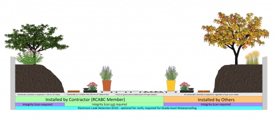
- Electronic Leak Detection is mandatory for grade-level Waterproofing Systems, but optional for roof Waterproofing Systems.
- Pre-curbs and Concrete Features:
- When concrete walls or structures are constructed without a pre-curb, all concrete surfaces must be fully and continuously enveloped with the primary roof membrane.
- While the application of non‐penetrating bonded tiling or other architectural finishes to the waterproofing membrane is acceptable for a RoofStar Guarantee, and is subject to approval by the membrane manufacturer, the removal, reinstallation or replacement of any bonded finish, in order to investigate and repair leaks under the terms of the Guarantee, is the responsibility of others.
- Modifications during the Guarantee Term:
- The Guarantor must be notified in writing of any modifications or repairs to the RoofStar-guaranteed project.
- The Owner must ensure that any modification or repair work done on the project during the guarantee period is performed to RoofStar Guarantee Standards by a Contractor, and is inspected by a RoofStar-accepted observation firm.
- Maintenance: the building owner must ensure that the project and its components are properly maintained. Debris in drains, caulking on or around metal flashings, and wind scouring of gravel are considered maintenance issues.
- Removal and Reinstallation of Overburdens: in order to investigate and repair a leak, the RoofStar Guarantee Program must be allowed to remove overburdens, to expose the membrane. The RoofStar Guarantee pays for the removal and reinstallation of accessible overburdens only (subject to the limits published below), when they are installed by the Contractor, regardless of the project design. The cost to remove, care for and reinstall any overburden that exceeds these limits or conditions, which is inaccessible, or which was supplied or installed by others, will be borne by the building owner.
- Maximum coverage area: limited to one physically defined project area (no maximum size)
- The RoofStar Guarantee pays for removal and reinstallation of accessible overburdens up to the following limits:
- Extensive vegetated roof systems, provided they are comprised of trays or other recognized modular methods and are less than 150 mm (6”) in depth, exclusive of the plants.
- other accessible coverings, provided they are unitized (for example, pavers on pedestals) and do not exceed 1 M2 or 90 Kg (200 lb.) per unit.
- gravel ballast and its associated drainage or protection material components, provided the ballast is less than 150 mm (6”) deep.
- structures, furnishings or planters provided each item, or any single component of each item, is easily detachable, does not require a specialty trade, and is no heavier than 90 Kg (200 lb).

2 SUPPORTING STRUCTURES: Decks and Walls
2.1 General
2.1.1 Definitions
Refer to the Glossary for further definitions of key terms used in this Manual.
- Supporting deck ("deck")
- means the "structural surface to which the waterproofing system or water-shedding system is applied" (adapted from ASTM D1079-18 Standard Terminology Relating to Roofing and Waterproofing).
- Deck overlay
- means a panel material secured to the supporting deck, to render the deck surface continuous or suitable for the installation of roofing materials.
- Wall
- means a structural or non-structural element in a building that vertically separates space. Walls may separate the outside environment from the interior conditioned space of a building, or they may separate one or more interior spaces from each other (adapted from ASTM E631-15 Standard Terminology of Building Constructions).
- Wall overlay
- means a panel material secured to the surface of a Wall, to render it suitable for the installation of roofing or wall cladding materials.
2.1.2 Design
- The British Columbia Building Code, or any other Code having jurisdiction, prevails in all cases except where it is exceeded by the RoofStar Guarantee Standards published in this Manual.
- Notwithstanding the requirements in this Standard, the RoofStar Guarantee does not extend coverage to the supporting deck or to its securement, which is the responsibility of the Design Authority and the building contractor.
- Prior to the application of the roof system, the supporting deck and other surfaces receiving membranes must be smooth, straight, clean and free of
- moisture.
- frost.
- dust and debris.
- contaminants.
- objectionable surface treatments.
- release oils.
- laitance.
- If surface drying is required prior to roofing, use blown air to facilitate this.
- Walls, parapets, curbs, blocking and penetrations should be constructed or placed prior to the commencement of roofing work. This work is provided by other trades.
- The supporting deck should be dimensionally stable and capable of accommodating roof system component movement.
2.2 Roof Slope
- The RoofStar Guarantee Program classifies roof systems according to their function – waterproofing systems or water-shedding systems. Within each classification, slope is defined as follows:
- Flat means a roof with a slope less than 1:6 (2” in 12”, or 9 degrees).
- Low Slope means a roof with a slope from 1:6 (2” in 12”, or 9 degrees) up to but less than 1:3 (4” in 12”, or 18 degrees).
- Common Slope means a roof with a slope 1:3 (4” in 12”, or 18 degrees) up to and including 1:1 (12” in 12”, or 45 degrees).
- Steep Slope means a roof with a slope greater than 1:1 (12” in 12”, or 45 degrees) up to and including 21:12 (21” in 12”, or 84 degrees).
- Extreme Slope means a roof with a slope greater than 21:12 (21” in 12”, or 84 degrees).
See Figure 2.1 for an illustrated guide to the above definitions.Figure 2.1 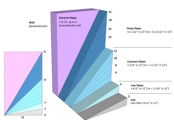
- RoofStar 15-year Guarantee: a minimum slope of 1:6 (2” in 12”) is required and may not be reduced through a written Variance.
- RoofStar 5-year and RoofStar 10-year Guarantees:
- A minimum slope of 1:6 (2” in 12”) is strongly recommended to ensure optimal performance of the roof system.
- When the designed slope is less than 1:4 (3/12), the engineered shop drawing package must be accompanied by manufacturer’s literature confirming that this application is acceptable.
- Roofs with designed slopes less than the stated minimum (such as curved applications; see also Part 9 PANELS) will be considered for a RoofStar Guarantee provided
- the design and installation details are submitted in writing to the Guarantee Program Administrator prior to the tendering of documents.
- a written Variance is issued by the Guarantor prior to close of tender.
See also Part 9 PANELS. - If proprietary systems are specified, the manufacturer's suggested minimum slope and application procedures must be followed in addition to RoofStar Guarantee requirements.

2.3 Supporting Deck Types
2.3.1 General
- All supporting decks must provide a suitable nailing substrate for asphalt shingles, and be acceptable to the shingle manufacturer. Suitability includes, without limitation,
- sufficient thickness for fastener holding.
- stiffness that minimizes deck deflection.
- Prior to the application of the roof system, the supporting deck and other surfaces receiving membranes must be smooth, straight, clean and free of
- moisture.
- frost.
- dust and debris.
- contaminants.
- objectionable surface treatments.
- release oils.
- laitance.
If surface drying is required prior to roofing, use blown air to facilitate this. - Walls, parapets, curbs, blocking and penetrations should be constructed or placed prior to the commencement of roofing work. This work is provided by other trades.
- The supporting deck should be dimensionally stable and capable of accommodating roof system component movement.
2.3.2 Wood Decks
- All wood decks
- must be affixed to the supporting framing or structure with corrosion-resistant
- wood screws.
- spiral nails.
- ring shank nails.
- with knots or cracks must
- have metal affixed over them before the deck can be accepted for roofing (this work should be done by others)
- be overlaid with a layer of knot-free 12.5 mm (1/2”) plywood
- must be affixed to the supporting framing or structure with corrosion-resistant
- The structural suitability of the fastener is the responsibility of the Design Authority.
- Plywood with a minimum thickness of 15.9 mm (5/8") is the only acceptable sheathing to be used for wood roof decks, unless applied over a solid lumber decks (including, without limitation, laminated timber and wood board decks). Tongue and groove plywood sheathing with a minimum thickness of 15.9 mm (5/8") is required for decks on all copper and zinc non-ferrous (i.e. copper, zinc) metal panel roof systems.
- Oriented Strand Board (OSB) is not an acceptable wood deck.
2.3.3 Steel Decks
- Steel decks must conform to one of the following specifications:
- ASTM Standard Specification A653 / A653M, Sheet Steel, Zinc-Coated (Galvanized) by the Hot-Dip Process, Structural (Physical) Quality, minimum Grade 33, with a design thickness of 22-gauge (0.759 mm) or greater and a minimum zinc coating designation Z275.
- ASTM Standard Specification A792 / A792M, Steel Sheet, Aluminum-Zinc Alloy-Coated by the Hot-Dip Process, General Requirements, minimum Grade 33, with a design thickness of 22-gauge (0.759 mm) or greater and a minimum aluminum-zinc alloy coating designation AZ150.
2.3.4 Concrete Decks
- Direct contact between metal roofing and concrete, light concrete, stone and mortar must be avoided. The selection of a suitable underlay, insulation, and method of attachment to a concrete deck or wall is the responsibility of the Design Authority.
2.4 [NOT USED]
2.5 [NOT USED]
2.6 Walls
2.6.1 General
- Wall surfaces must be clean, dry and smooth, suitable for the application of roof system materials. When the wall surface is unsuitable to receive waterproofing materials, it must be resurfaced with an RoofStar-accepted wall overlay. See Part 5 DECK and WALL OVERLAYS for material and application standards.
- Sheathing, defined as a rigid panel material secured directly onto framing, is considered a wall surface for the purpose of this Standard.
- Wall surfaces receiving waterproofing materials must extend vertically beyond the maximum height of waterproofing materials but in any event must be installed at least 200 mm (8”) high, above the surface of the finished water-shedding system. For suitable wall surface materials, see 2.6.2 below.
- Walls and roofs commonly intersect in two ways:
- Directly, where the wall structurally connects to the roof structure, so that both move together.
- Indirectly, where the roof structure and the wall structure are independent of each other, so that the movement of one does not affect the other. These locations require an expansion joint.
- The Design Authority must ensure a continuous connection between the roof system from field to perimeter, in order to control or inhibit the movement of water, air and vapour.
- Wood or steel-stud walls must be sheathed with a material suitable for securing linear metal flashings.
- For concrete walls, refer to 2.2.3 Concrete above.
2.6.2 Materials
- Concrete surfaces must comply with the requirements set out in 2.1.3. When concrete surfaces do not comply, concrete walls may be sheathed with any one of the following:
- 15.9 mm (5/8”) thick treated plywood.
- fibre-mat reinforced cement boards with a minimum thickness of 9.5 mm (⅜").
- Both materials must also conform to ASTM C1325-04.
- For framed walls, the following sheathing material are acceptable:
- Moisture resistant fibreglass-faced silicon treated gypsum core board specifically designed to receive roof membranes; boards must have a minimum thickness of 12 mm (1/2”). These panel may be installed horizontally or vertically.
- Fibre-mat reinforced cement boards with a minimum thickness of 9.5 mm (⅜").
- Plywood with a minimum thickness of 12 mm (1/2”).
2.7 Electrical Cables and Boxes
Electrical cables (including conduit) or boxes installed inside, on top of, or beneath a roof assembly may expose roofing workers to electrical shock, and may inhibit the installation of some roof systems designed to resist wind uplift. Furthermore, electrical cables on, in or under the roof assembly expose the building and the public to both shock and fire. Hidden electrical wiring and boxed junctions can be extremely difficult to document before work begins, and while some technologies are purportedly accurate in identifying energized circuits before they are damaged, false readings make these technologies less than reliable. During replacement roofing, avoiding damage to electrical circuits from cutters and fasteners is sometimes next to impossible. It is therefore desirable to design buildings with realistic separations between electrical wiring and boxes, and roof assemblies.
For more about this topic, see the Information Bulletin reissued by Technical Safety BC (formerly BC Safety Authority) in June 2020.
Currently, neither the Canadian Electrical Code, Part I nor the British Columbia Electrical Code expressly prohibit, nor expressly permit, the installation electrical cables and boxes anywhere in close proximity to a roof assembly. The Design Authority therefore has the latitude to write restrictions concerning the location of electrical installations, and consequently eliminate shock and fire hazards. To do so, apply the following standards when preparing Project specifications to qualify for a RoofStar Guarantee.
2.7.1 New Construction
- Electrical cables, raceways or boxes shall not be installed within a roof assembly(Figure 2.7.1-1).
- Electrical cables, raceways or boxes shall not be installed on the underside of a roof assembly, unless
- the supporting deck structure equals or exceeds 76 mm (3”) in thickness(Figure 2.7.1-2), or
- the cables, raceways or boxes are installed and supported so there is a separation of not less than 38 mm measured between the underside of the roof assembly and the electrical installation(Figure 2.7.1-3).
- Notwithstanding either (1) and (2), cables or raceways shall be permitted to pass through a roof assembly for connection to electrical equipment installed on the roof, provided that the passage through the roof is a part of the roof assembly design.
- Electrical cables installed above the roof assembly should be elevated to permit proper support, roof maintenance and future replacement roofing (Figure 2.7.1-4).
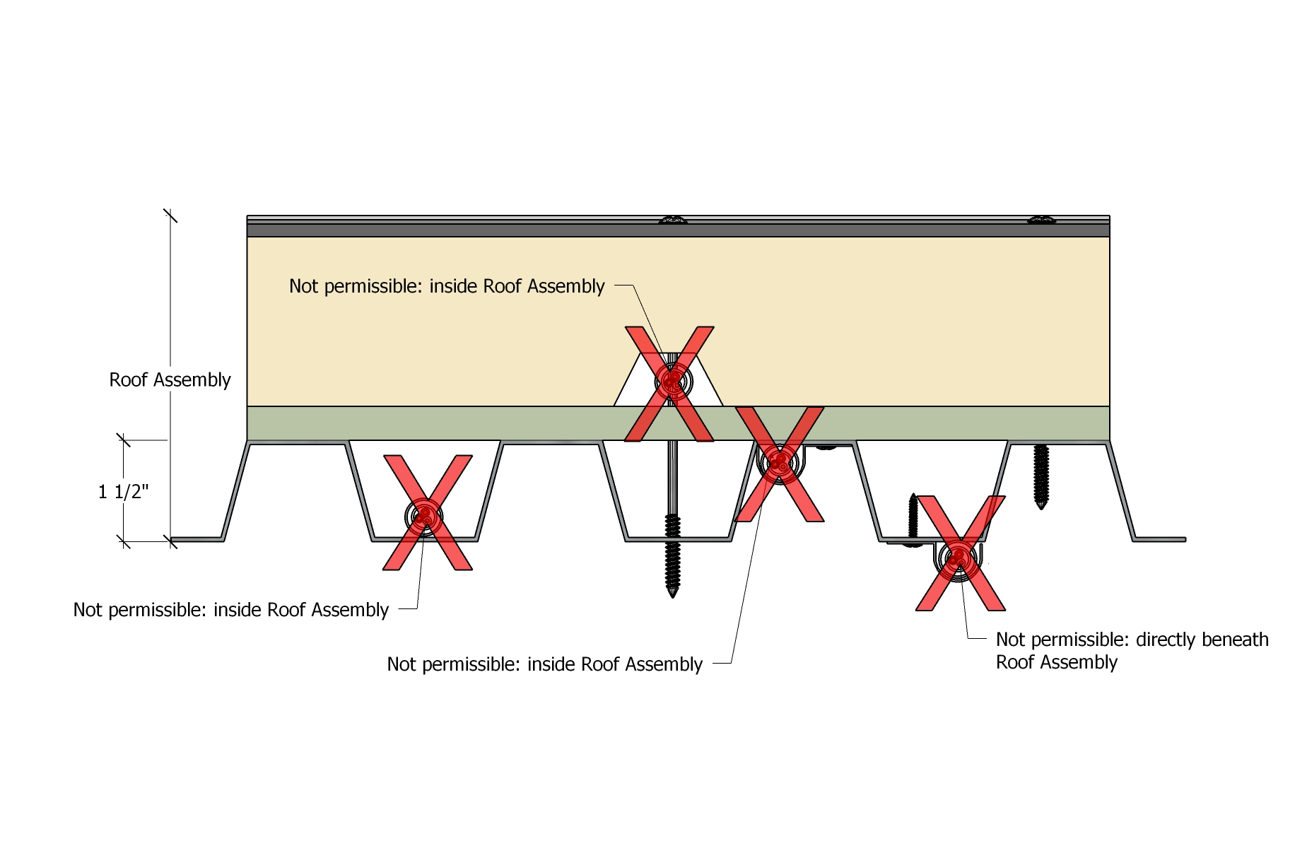
|
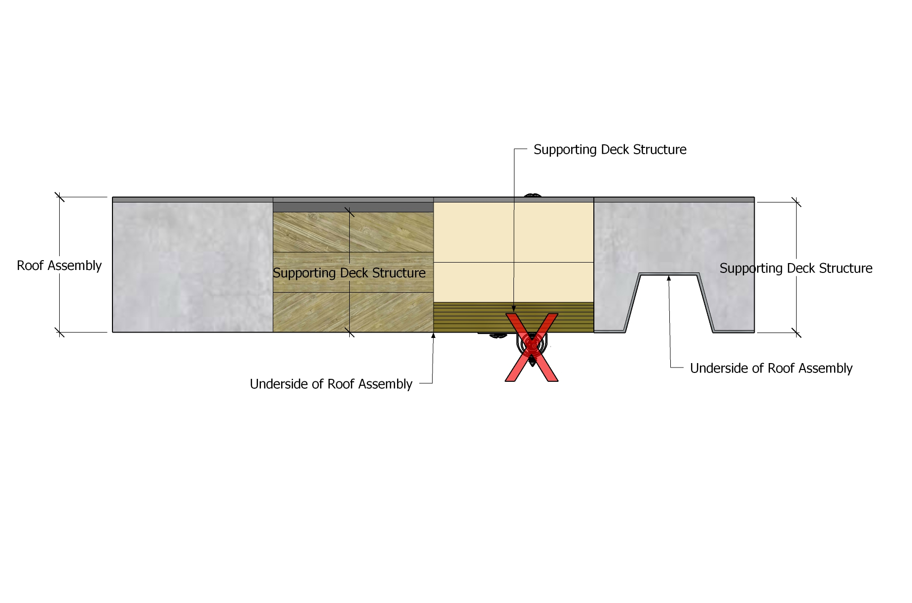
|
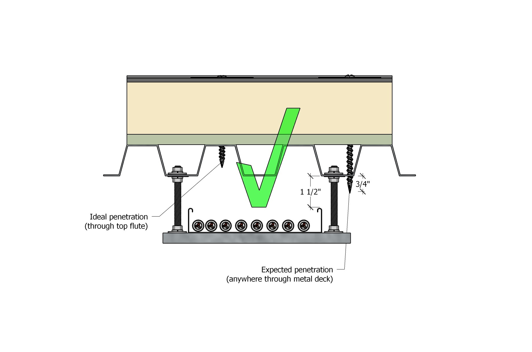
|
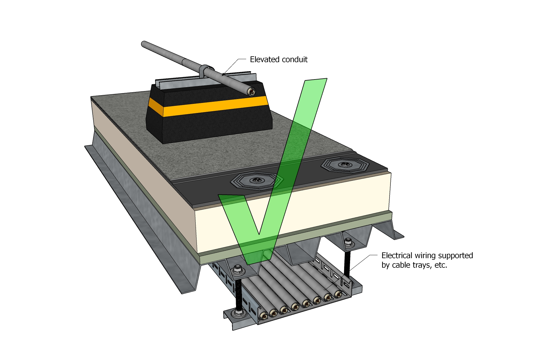
|
2.7.2 Replacement Roofing
- If existing electrical cables or boxes do not conform to the standards in 2.7.1 New Construction, the Design Authority must consider the attachment of the roof system above the electrical system, and the requirements set out in Part 3 SECURING the ROOF ASSEMBLY.
- The Design Authority should
- specify protection of existing electrical cables and boxes (a 5 mm (3/16”) steel plate may be used to minimize the possibility of fastener penetration and cutter damage), but it should be understood that protection plates may interfere with mechanical fasteners used to secure the roof system against wind uplift, even for future replacement roofing).
- provide the building owner with detailed as-built drawings that accurately map the location of electrical cables and boxes.
3 SECURING the ROOF ASSEMBLY
3.1 General
3.1.1 Design and Testing
The Design Authority is responsible to design the securement of the roof system, as required under 9.1.1 Design. The following information is a reference tool for designers, to be used at their own discretion.
The RoofStar Guarantee Program (RCABC Guarantee Corp., or RGC) initiated an investigation to establish the wind uplift resistance of architectural concealed fastener metal roof systems for use in British Columbia. The wind uplift tests were carried out at the Dynamic Roofing Facility at National Research Council, Institute for Research In Construction (NRC/IRC). NRC/IRC report No. B1040–3 (see ASM Application Guides and Notes) provides a simplified procedure for wind uplift design for roof assemblies with architectural metal roof coverings. In addition, NRC / IRC reports No. B1040-1 and B1040-2 provided the wind resistance test results for RoofStar-accepted metal panel systems and assisted the RoofStar Guarantee Program in developing guarantee standards and acceptance criteria for RoofStar-accepted Architectural Sheet Metal Roof Systems.
3.2 Materials
3.2.1 Fasteners, Clips and Cleats
- For specific requirements, see below under Part 9, Part 10 and Part 11.
3.3 Application
- All metal panels must be secured to their underlying supports with concealed fasteners. Exposed fastener securement is not acceptable.
- Concealed fasteners should provide clearance for the underside of the metal panel and must be of a material compatible with the metal clip.
- Regardless of where fasteners are used in the roof system, when they penetrate and secure another material to a substrate, mechanical fasteners must penetrate
- through the bottom surface of
- steel decks at least 20 mm (3/4") – fasteners should penetrate the top flutes only.
- plywood sheathing by at least 19 mm (3/4").
- into solid dimensional lumber or concrete by at least 25 mm (1").
See Figure 3.5.Figure 3.5 (Click to expand) 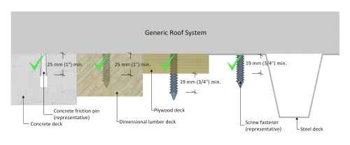
These Standards may be exceeded by the fastener manufacturer’s published requirements. - through the bottom surface of

4 MATERIALS
NOTE: Click here to view all the Materials accepted for use in the RoofStar Guarantee Program.
4.1 General
- All roofing components installed by the Contractor must be
- new
- accepted by the RoofStar Guarantee Program.
- manufactured by, or listed as acceptable to, the manufacturer of the primary field membrane or water-shedding material.
A list of all Accepted Materials is published in this Manual (see link above).Also see 1.6 (2) RoofStar Guarantee: Coverage and Limitations for restrictions and limitations on any roofing material, linear metal flashing, penetration flashing or drain used on a project qualifying for a RoofStar Guarantee.
- All materials must be protected from weather, properly stacked and secured above ground or the roof surface and covered by wrappers approved or recommended by the manufacturer.
- All installed roofing materials that are susceptible to moisture damage must be made watertight by the end of each work day.
- Metals and fasteners must be compatible with each other, to avoid galvanic corrosion which can occur when dissimilar metals contact each other.
4.1.1 Definitions
Refer to the Glossary for further definitions of key terms used in this Manual.
- Primary Material
- means a roofing, waterproofing or water-shedding material which is directly exposed to the weather and which is primarily responsible for protecting secondary materials, and the building interior, from water and weather generally. Membranes, metal panels or shingles form the core of this material category.
- Secondary Material
- means one which forms part of a waterproofing system or water-shedding system and which may affect the wind resistance characteristics of the entire assembly but is not necessarily exposed to the weather.
5 DECK and WALL OVERLAYS
5.1 General
5.1.1 Definitions
Refer to the Glossary for further definitions of key terms used in this Manual. See also 2.1.1 Definitions..
5.1.2 Design
- When a supporting deck structure or wall is unsuitable for the application of roofing materials, it must be covered with a RoofStar-accepted overlay. See 2.1 (3) for supporting deck and wall surface requirements.
- A roof deck overlay is installed as part of the roof assembly, on the top surface of the roof deck but beneath the roofing materials. These products are commonly affixed to steel decks to provide a level surface for the roof membrane or air or vapour control layers, or to serve as a thermal barrier between the roof deck and combustible insulation. Roof deck overlay materials may also be applied to other types of supporting deck structures, depending on the roof design criteria.
- Wall overlays are less common on water-shedding systems but may be required to provide a suitable surface for self-adhering membrane flashing.
- For roof assemblies designed above a vaulted conditioned space, see also 6.1.3.2 Attic Ventilation.
5.2 Materials
- Deck overlays and wall overlays must be suitable for, and compatible with, any membrane or panel application. Plywood, measuring at least 12.7 mm (1/2”) in thickness, is acceptable as a deck overlay or wall overlay.
- When the Code having jurisdiction requires a thermal barrier, an accepted deck overlay must be specified and installed.
- Walls that require resurfacing for membrane application must be covered with an accepted wall overlay. See Accepted Wall Overlays. See also Accepted Deck Overlays.
5.3 Application
5.3.1 General
- Deck overlays must be
- fully or intermittently supported along all edges by the deck.
- installed in a staggered pattern (offset) at least 300 mm (12") from adjacent board rows. A minus offset tolerance of 50 mm (2") maximum will be permitted to compensate for variance in the manufacturer's tolerance of differing board widths and lengths.
- affixed to the deck with either
- mechanical fasteners, and/or
- proprietary polyurethane foam adhesives acceptable to the primary roof system manufacturer to meet or exceed the requirements set out in 3 SECURING the ROOF ASSEMBLY.
- independently fastened to the deck
- with at least four (4) fasteners (with plates) per 1200 x 2400 (4’x8’) sheet, or
- as specified by the Design Authority.
- Wall overlays
- must be applied to existing sheathing where sheathing is not an acceptable substrate.
- may be mechanically fastened or adhered.
5.3.2 Steel Decks
- Deck overlays used as a thermal barrier to achieve a specific fire rating must conform to the applicable Code and insurance requirements for the roof assembly.
- When the roof assembly is uninsulated, the deck must be overlaid to provide a continuous layer of support. The deck overlay must be at least one layer (min. 12.7 mm (1/2”)) of either
- 1) moisture resistant fibreglass-faced silicon treated gypsum core board.
- plywood.
5.3.3 Wood Decks
- A mechanically-fastened overlay board is required for any supporting deck that does not meet the deck fastening criteria set out in 2.3.1 Wood Decks.
5.3.4 Concrete Decks
- While metal panels must be separated from a concrete deck to prevent corrosion, a deck overlay is not mandatory, and separation may be made with an underlayment.
5.3.5 Walls
- Where the wall surface is unsuitable to receive a membrane, it must be covered with an accepted overlay panel material (refer to Division C: Accepted Materials in this Manual).
- Wall overlays must be
- mechanically fastened with screw fasteners placed
- at the perimeters.
- at the corners.
- in the field, spaced no less than 300 mm (12”) O.C. vertically and horizontally, or in alignment with structural supports of the overlay panels.
- adhered with a polyurethane adhesive, applied with a continuous z-patterned ribbon spaced no less than 300 mm (12”) apart, in alignment with structural supports.
- mechanically fastened with screw fasteners placed
6 AIR and VAPOUR CONTROLS
NOTE: See more information on Air and Vapour Control in Division B: Essential Elements.
6.1 General
6.1.1 Intent
Air and vapour control layers, along with thermal barriers, water resistive barriers and water-shedding surfaces, serve to separate the outside environment from the interior environments of a structure. Continuous air control layers are perhaps the most critical. Codes in each jurisdiction, and the National Energy Code (2011), require the selection and proper installation of “a continuous air barrier system comprised of air-barrier assemblies to control air leakage into and out of the conditioned space” (NEC 2011).
Continuity of the air and vapour control layers from the wall systems and roof systems is essential to the satisfactory performance of either or both. Therefore, proper connection between air and vapour control systems is essential, and the responsibility of both the Design Authority and trades constructing walls and roofs.
Air control layers control “flow of air through the building enclosure, either inward or outward” (Guide for Designing Energy Efficient Building Enclosures, Homeowner Protection Office). Controlling air flow into and out of conditioned spaces affects the performance of “thermally efficient enclosure assemblies” (ibid), impacts the potential for condensation in between materials, and directly influences rain water penetration of the building envelope. Some air control layers are considered vapour permeable, others vapour-impermeable. The suitability of one over the other, in the application of a roof system, is left to the discernment of the Design Authority. Consequently, the RoofStar Guarantee Program strongly recommends that designers and builders of roof systems intended to qualify for a RoofStar Guarantee carefully consider the regulatory design and installation requirements for effective, continuous air control systems.
Vapour control layers regulate or prohibit the movement of water vapour from one space to another by means of diffusion. Consequently, these control layers are referred to as either vapour-permeable or impermeable. Diffusion is a slow process, in contrast to air movement, and its regulation is not always mandatory or even desirable. Therefore, because continuous vapour control layers “are not needed within all climate zones and assemblies”, they are considered non-critical and may be left to the discretion of the Design Authority. Nevertheless, where continuous vapour control layers are required and specified by Code, the RoofStar Guarantee Program requires that a suitable vapour control system be selected by the Design Authority and properly installed by the Contractor in conformity with the vapour control layer manufacturer’s published instructions, and with the Design Authority’s specified details.
Any references in this Manual to installation methodologies, and any construction details that show air and vapour control layers, are merely illustrative and not prescriptive. Installers of continuous air and vapour control layer systems are urged to understand and comply with best practices for their application.
6.1.2 Limitations and Exclusions
- Air and vapour control layer performance is not part of the RoofStar Guarantee, and air and vapour control materials are not listed in the Accepted Materials Division of this Manual. Therefore, the decision to specify air and vapour control layers, the placement of continuous air and vapour control layers in relation to a roof system and its components, and the selection of suitable materials for that application, is the sole responsibility of the Design Authority. The Design Authority is urged to review and consider the performance characteristics of materials available for such applications.
- Neither the RoofStar Guarantee Program nor the Contractor will accept any responsibility for damage to, or failure of, the roof system caused by the use or absence of air or vapour control layers.
- In some roof assembly designs, the required underlayment may serve as an air control layer, vapour control layer, or both; this is dependent upon the properties of the material to be used, and will be subject to the designer’s modelling of the assembly. Consult the Technical Data Sheets for suitable materials.
6.1.3 Design
6.1.3.1 Vapour Retarder Design for High-Humidity Building Interiors
- Careful consideration should be given to the performance characteristics of air and vapour control layers when specifying such a membrane for roof systems constructed over high-humidity building interiors. These types of building interiors include (but are not limited to)
- swimming pools
- commercial laundry facilities
- large aquariums
- paper mills
Roof systems for facilities such as these, with high-humidity environments, may be susceptible to the accumulation of moisture within the roof system unless effective air and vapour controls are installed.
6.1.3.2 Attic Ventilation
- The design and selection of the ventilation system is the responsibility of the Design Authority, and may be achieved by incorporating into the roof design both intake and exhaust vents, including (without limitation),
- eave vents
- gable end vents
- hip vents
- static vents
- ridge vents
- cupolas
- Attic (roof cavity) ventilation must
- meet the minimum requirements set out by the Code having jurisdiction, even in conditions where snow cover is present (see British Columbia Building Code, Part 9 for Housing and Small Buildings, Section 9.19 Roof Spaces, 9.19.1.3 Clearances). Roofs that do not provide adequate ventilation do not qualify for a RoofStar Guarantee.
- be suitable for the
- slope of the roof.
- vented area.
- design and configuration of the roof structure.
- be provided for
- roofs over cathedral ceilings.
- compact insulated roof assemblies.
See also Building Ventilation in Division B: Essential Elements of this Manual.
- Continuous ridge venting systems
- are acceptable and are recommended for all areas with vaulted ceilings.
- may be installed on slopes 1:3 (4” in 12”) and greater, but application on slopes less than 1:3 must be permitted by manufacturer’s published installation instructions.
6.2 Materials
6.2.1 Air and Vapour Controls
- The material selected for air and vapour control layers must be compatible with any other materials in the roof or wall assembly to which the control layer may come in contact. This includes, without limitation, contact with primers and adhesives, substrates, solvents and cleaners.
- Self-adhering or adhesive-applied materials should be considered as alternatives to torch-applied membranes when the substrate to which they will be applied is combustible, or when nearby structures, openings or materials present a fire hazard. In the alternative, a suitable separation or overlay material as protection from open flame is acceptable. The application of materials to a combustible surface, using a torch, is strictly prohibited.
- Fully supported air and vapour control layers should possess a minimum published static puncture resistance rating of 150 N (34 lbf) (ref. CGSB-37.56-M for both test method and standard limits) and be either self-adhering or torch-applied; a high puncture resistance is necessary for the membrane to withstand accidental damage during construction. For unsupported air and vapour control layers, see 6.2 (4) below. Therefore, while responsibility for the selection of suitable air and vapour control layers rests with the Design Authority, a roof designed and built to qualify for a RoofStar Guarantee shall not include the following:
- polyethylene sheet plastic.
- bitumen-impregnated kraft paper.
- Notwithstanding any of the foregoing, the RoofStar Guarantee Program strongly recommends that any air or vapour control systems be installed over a smooth, continuous plane (for example, concrete or plywood). Consequently, a deck overlay board installed on corrugated steel roof decks in highly recommended. Where no deck overlay board is installed and the air and vapour control layers are partially unsupported (for example, on a steel deck), the control layers each must have a published static puncture resistance of at least 400 N (90 lbf). Furthermore, both the side laps and end laps must be fully supported.
- Should the air or vapour control layers be used as a temporary roof during project construction by either the Contractor or by other trades, a minimum 2mm thick bituminous membrane is recommended.
- Because curing concrete releases considerable moisture that can compromise the performance of a roof system, a vapour control layer installed on new concrete decks (28 days or older) must be selected to prevent condensation inside the roof system. A membrane with a permeability of 0.01 perms (Class I) is recommended. Nevertheless, the selection of the vapour control material is the responsibility of the Design Authority.
6.2.2 Air Vents
- Vents, regardless of their type, must be either
- proprietary to, or privately labeled for, the panel manufacturer, or
- specifically accepted by the RoofStar Guarantee Program. See also 11.2.3 Penetration Flashings.
- Ridge vents must be
- fabricated from a compatible metal.
- acceptable to the metal panel manufacturer.
- suitable for slopes 1:4 and greater.
- constructed with internal baffles to prohibit the intrusion of
- insects.
- vermin.
- snow.
- debris.
6.3 Application
6.3.1 Air and Vapour Controls
- Proper installation and continuity of air and vapour control layers within the roof assembly is the responsibility of the Contractor. Therefore, air and vapour control layers in the roof assembly must
- extend beyond the end of the roof assembly at least 100 mm (4”), in new construction, to provide sufficient room for the installation of matching control layers to so that they provide a positive (water-shedding) lap seal union between courses of material.
- be sealed to matching control layers in the wall assembly, for roof replacement projects.
- Installation must be smooth and uniform, without wrinkles or fish-mouths, and must also conform to the manufacturer’s published requirements and the Design Authority’s design details.
- All membrane side and end laps must be fully supported, in the field and at transitions with curbs, parapets, walls and penetrations. When self-adhered membranes are applied directly to a steel supporting deck,
- membranes should be oriented parallel to the direction of deck flutes.
- membrane laps and changes in plane must be supported by deck flutes or flat metal supports secured to the deck to span gaps. Metal supports must be
- fabricated from pre-finished steel with a thickness no less than 24 Gauge.
- secured to the deck with no fewer than two (2) compatible screw fasteners per flute.
- The application of materials to an unprotected combustible material, using a torch, is strictly prohibited.
- All combustible materials MUST be protected from open flame by an acceptable separation or overlay material. This includes, without limitation, combustible materials
- on decks, walls, blocking, and canted edges.
- hidden or obscured within voids, cracks or orifices.
- When a torch-applied base membrane is specified over combustible materials, all joints between overlay panels, and at roof-wall transitions, must be sealed with the primary membrane manufacturer’s approved self-adhered membrane or tapes. Alternatively, refer to 10.3.3 Alternative Approaches to Membrane Flashing in the RoofStar Guarantee Standards for SBS Modified Bitumen Membrane System.
See Figures 6.3.1-1 and 6.3.1-2.

|

|
6.3.2 Air Vents
- Refer to 11.3.3 Penetrations and Vents for application requirements.
7 INSULATION
7.1 General
- Some water-shedding systems call for a compact insulated system, as for example when the roof covers a vaulted conditioned space. When this is the case, the following design, material and application requirements, principles and recommendations apply.
7.1.1 Definitions
- Heat-resistant insulation
- means insulation that resists heat and will not physically or chemically change when exposed to heat greater than 70°C (158°F), including liquefied bitumen. Insulation boards of this type include fibreboard, polyisocyanurate and mineral wool. Note that heat-resistant does not mean or even infer 'fire-proof'. While some heat-resistant insulation materials will resist burning for a period of time, only mineral wool insulation will not burn.
- Heat-sensitive insulation
- means insulation that may be physically or chemically altered when exposed to heat greater than 70°C (158°F) - for example, heat from a torch or from liquefied bitumen. Heat-sensitive insulation includes EPS, XPS and polyurethane.
See the Glossary for other terms used in this Part.
7.1.2 Design
- The use of thermal barrier between the roof deck and insulation is the responsibility of the Design Authority and may be required by the Code having jurisdiction. Consult the Code for the minimum required thermal resistance of the roof system. See also Part 5 DECK and WALL OVERLAYS.
- Insulation compressive strength must be taken into consideration by the structural engineer.
- Insulation materials rely on various standards for the determination of thermal resistance, which means that not all data can be easily compared. Furthermore, not all insulation products perform with consistent thermal resistance as temperature changes, and some insulation performance declines with age. The Design Authority is therefore urged to consider the Long-term Thermal Resistance (LTTR) for each product, in relation to its placement within the roof system and the anticipated outside and interior climates of the building.
- In warm seasons, the roof surface may reach temperatures higher than 85°C (185°F), affecting the performance and stability of some insulation. Combining insulation types in a roof system may help mitigate these temperature swings and consequential distortion of the system. The Design Authority therefore must consider these variables when specifying materials and their installation.
- Only heat-resistant insulation may be used directly beneath metal panels or flashings.
- When heat-sensitive insulation is used in the primary thermal assembly, it must be covered with a heat-resistant insulation at least 50 mm (2”) thick. See also 7.1.2(9) below.
- Insulation assemblies with a cumulative thermal resistance greater than RSI-2.64 (R-15) (based on published LTTR values measured at 24°C) must be installed in multiple layers that are offset and staggered (see 7.3 Application). Within that multi-layered assembly, any single layer of insulation may have a thermal resistance greater than RSI-2.64 (R-15) provided no one layer exceeds 60% of the cumulative thermal resistance of the combined assembly of insulation and insulation overlay boards.
See Figure 7.1.Figure 7.1 (Click to expand) 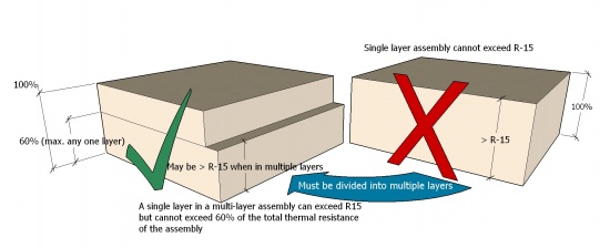

7.2 Materials
- The type of insulation is to be specified by the Design Authority. A list of acceptable insulation materials may be found in Roof Deck Insulation.
- Material dimensions:
- The maximum width and length of any adhered insulation panel shall be 1200 mm (4’) (see also 3.3.2 Adhesive Applied and 7.3.2 (4) below).
- The maximum width and length of insulation boards installed with mechanical fasteners is limited only by the manufacturer.
- Insulation installed directly over a fluted steel deck must be thick enough to span the flutes under live loads, without risk of cracking or breakage.
- While minimal insulation panel thicknesses are permissible for some designs, the Design Authority should consider the constructability of the roof system from a material handling perspective. Therefore, when materials are by their nature breakable, the specifier should consider specifying a thicker panel.
7.3 Application
7.3.1 Layering
- See 7.1.2(8) above.
- Insulation board joints must be offset at least 300 mm (12"), both for adjacent layers and for adjacent rows; a minus offset tolerance of 50 mm (2") maximum is permissible (see Figure 7.3).
Figure 7.3 (Click to expand) 
- Only thermally non-conductive clips or bars passing through the insulation assembly, or mechanically fastened bearing plates, may be used to secure and support insulation panels, or provide support for panel clips. When thermally non-conductive clips or bars are utilized on a Low Slope roof, they must be embedded in, and fastened through, a compatible sealant (see 9.2.5 Sealants).
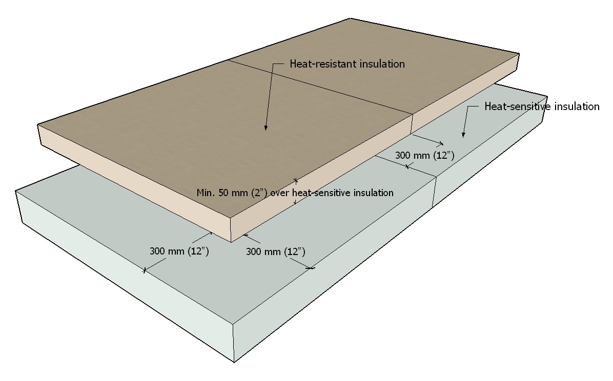
7.3.2 Alignment, Sizing and Support
- On steel roof decks, insulation boards must be firmly supported.
- Insulation boards must be
- firmly supported.
- square and make firm, full contact with adjacent panels. Gaps greater than 10 mm (3/8”) between boards must be filled with expanding spray foam or chinked with fibreglass wool.
- offset at least 300 mm (12"), both for adjacent layers and for adjacent rows.
7.3.3 Securement
Refer to 3 SECURING the ROOF ASSEMBLY.
8 EAVE and VALLEY PROTECTION, UNDERLAYMENTS and VENTILATION
8.1 General
8.1.1 Definitions
- Eave and Valley Protection
- means a self-adhering membrane applied in valleys and in parallel courses on the roof deck along the eaves, up the roof slope to a point measured vertically from the inside of the exterior wall, and intended to block the ingress of water that may leak behind shingles or metal roof panels as the result of snow or ice buildup on the roof surface.
- Separation Layer
- (sometimes referred to as a "slip sheet") means a roll material installed directly below metal roof panels to
- inhibit bonding of the metal panels to underlying materials, such as bitumen-based underlayments or eave protection membranes, or
- permit the passage of vapour out of the roof system.
- A separation layer by itself does not function as a ventilation layer.
- Underlayment
- means a roll material that is either self-adhering or mechanically fastened (typically with large head nails), and which is installed
- immediately over the supporting deck.
- to provide secondary protection between the water-shedding system materials and the building interior.
- to keep water-shedding system materials from adhering to the deck..
- Ventilation Layer
- means a layer of roll material, usually comprised of stiff, synthetic entangled mesh, installed directly beneath the metal panels in place of, or in addition to, a separation layer; it creates a ventilation space intended to
- facilitate the drying of condensation that collects on the bottom surface of metal roof panels.
- inhibit bonding of metal roof panels with underlying materials.
See the Glossary for other terms used in this Part.
8.1.2 Design
- Eave and Valley Protection
- must be installed on the supporting deck.
- is required for all RoofStar-guaranteed Architectural Sheet Metal Roof Systems. Eave protection must be a RoofStar-accepted self-adhered modified bituminous membrane.
- may also serve as an air or vapour control, or as both, when installed in combination with the underlayment. See also 6.1.2 above.
- must be carried a minimum of 600 mm (24") inside interior walls, or 900 mm (36") in heavy snow load conditions (For RoofStar Guarantee purposes, high snow load is considered regional areas with snow loading higher than 3.5 kPa as referenced in the National Building Code of Canada, Appendix C “Climatic Information for Building Design in Canada”. See also 1.3.3 High Snow Loads).
- Underlayments
- are required over the entire supporting deck surface.
- A separation layer
- that is vapour-permeable is required on all insulated Architectural Sheet Metal Roof Systems and must be located between the insulation and metal panels.
- is required on all uninsulated roof systems when the underlayment is bitumen-based and does not incorporate a bond-breaking facer.
- A Ventilation space beneath metal panels
- is required beneath panels on slopes less than 1:3 (4” in 12”).
- is recommended when the roof slope exceeds 1:3 (4” in 12”). See 8.1.2 (4).
- Ventilation may be achieved by either of the following options:
- Support the metal panels with entangled mesh having a thickness of at least 7 mm (1/4”) and secure the panels with standard panel clips supported on EPDM pads equal in thickness to the entangled mesh (9.2.4 (3)). See also 8.2.4 Ventilation.
- Elevate unsupported metal panels above the underlying substrate materials by at least 10 mm (3/8”) and secure the panels with tall panel clips; EPDM pads and entangled mesh are not required. This approach is acceptable to the Guarantor provided the Design Authority supplies the Guarantor with written engineering certification that
- the clips will adequately secure and support the elevated panels.
- the panels are suitable as spanning members and will support anticipated live loads (see 1.3 (1); also see 9.1.1 (9)).
8.2 Materials
Accepted materials for this purpose are listed in the Eave Protection & Underlayment (Architectural Metal Roofing) table of this Manual.
- Materials used for eave or valley protection, as an underlayment or as a separation layer must
- be selected from the list of Accepted Materials.
- not damage the painted finish of roof panels (a scratched or marred finish may result in panel corrosion).
- When a material not listed in the Accepted Materials is specified for application in an Architectural Sheet Metal Roof System, the Design Authority must request a written Variance from the Guarantor.
- All membranes must provide proprietary sealants, mastics, tapes and/or primers suitable for the application of the underlayment and must be applied in accordance with the manufacturer’s written instructions.
8.2.1 Eave and Valley Protection
- Membranes used for eave and valley protection must be
- self-adhering.
- have a sanded or synthetic, non-bonding top surface.
- at least 1 mm thick when the roof slope exceeds 1:6 (2” in 12”).
- at least 3 mm thick when the roof slope is less than 1:6 (2” in 12”).
8.2.2 Underlayment
- For Common Slope roofs (sloped from 1:6 (2" in 12") up to but not including 1:3 (4" in 12")), a continuous self-adhesive membrane underlay must be installed prior to the application of the sheet metal roofing. Direct torch application to wood surfaces is not permitted.
- Synthetic underlayments are permissible for slopes 1:3 (4” in 12”) and greater.
- For Low Slope roofs (sloped less than 1:6 (2” in 12”)), underlayments must be a continuous self-adhesive or thermally fused membrane with a minimum thickness of 3.0 mm, but this is subject to approval of the design by the RoofStar Guarantee Program. Contact the RoofStar Guarantee Program for a project review.
- Modified bituminous underlayments utilized directly beneath metal roof panels and flashings, or otherwise protected by insulating materials, must be made of bitumen with a high softening point and a minimum flow temperature of 87.7°C (190°F) ASTM D5147 high temperature stability.
8.2.3 Fasteners
- While mechanical fasteners used to secure underlayments must conform to the underlayment manufacturer’s requirements, the use of staples is not permitted.
8.2.4 Separation Layer
- Refer to Division C: Accepted Materials of this Manual.
8.2.5 Ventilation Layer
- Entangled mesh used in a ventilation cavity must be
- at least 7 mm (1/4") thick.
- capable of supporting the weight of the roof system and its anticipated live loads (see 9.1.1 (9)).
8.2.6 Linear Metal Flashings
- See Part 13 METAL FLASHINGS.
8.3 Application
8.3.1 Eave and Valley Protection
- Eave protection must be carried a minimum of 600 mm (24") inside interior walls, or 900 mm (36") in heavy snow load conditions.
- Valley protection membranes must be
- the same materials used for eave protection.
- at least 1000 mm (39”) wide and centred on the valley.
- positively lapped and sealed to the eave protection membrane.
- Where curbs are incorporated into the roof design, they must be flashed with the same material used for eave and valley protection. See 11.3.4 Curbs for additional requirements.
8.3.2 Underlayment
8.3.2.1 General
- All roof assembly components installed above the supporting deck must be installed by the Contractor.
- An underlayment is required for all slopes. See 8.2.2 for material requirements.
- Horizontal runs of underlayment must be positively lapped at least 50 mm (2"), and end laps (vertical joints) must be at least 150 mm (6").
- Where negative (backward) laps are unavoidable, only a self-adhering underlayment may be used. Negative laps must be at least 150 mm (6"), and seams must be roller-pressed and sealed with a compatible mastic along the seam edge.
- Underlayment must be installed horizontally on slopes up to 2:3 (8” in 12”).
- Underlayment may be installed perpendicular to the eaves provided the laps are self-sealing or sealed with a suitable lap cement provided by the underlay manufacturer. On slopes steeper than 2:3 (8” in 12”) underlayment installed vertically (perpendicular to the eaves) must
- be self-adhering.
- extend beyond the furthermost edge of the flashing at least 100 mm (4").
- positively lap beneath other vertical membranes.
8.3.2.2 Low Slope Roofs
- In addition to the General requirements above, Low Slope roofs may be fully covered with
- one layer of self-adhering eave protection membrane equal to or exceeding the minimum thickness requirements, or
- multiple layers equal to or exceeding 1.4 mm in thickness; the second layer must be offset from the first by at least 300 mm (12”), both horizontally and vertically.
8.3.3 Separation and Ventilation Layers
- A separation layer (slip sheet) is required when
- metal panels or flashings come in direct contact with any bituminous underlayments that do not have a tri-laminate facer.
- soldering is to be done.
- Horizontal runs of the separation layer must be positively lapped at least 50 mm (2") and end laps (vertical joints) must be at least 150 mm (6").
- For roofs designed with a slope less than 1:3 (4” in 12”), a ventilation space beneath the metal panel is required and may be achieved by either of the following options which the design will specify:
- Support the metal panels with entangled mesh having a thickness of at least 7 mm (1/4”) and secure the panels with standard panel clips supported on EPDM pads equal in thickness to the entangled mesh (9.2.4 (3)).
- Elevate unsupported metal panels above the underlying substrate materials by at least 10 mm (3/8”) and secure the panels with tall panel clips; EPDM pads and entangled mesh are not required. This approach is acceptable to the Guarantor, subject to the conditions in 8.1.2 Design.
9 PANELS
This Part covers metal panels that are site-formed by Contractors or manufactured by a supplier, for installation in an Architectural Sheet Metal Roof System. Both options are listed under the Accepted Architectural Sheet Metal Roofing table of this Manual.
9.1 General
9.1.1 Design
- To qualify for a RoofStar Guarantee, all Architectural Sheet Metal Roof Systems must be professionally engineered and documented on a Schedule S form (Specialty engineering; see the British Columbia Building Code, current edition). Roofs must be engineer-designed to
- withstand all anticipated live and dead loads, including but not limited to wind and other environmental loads (i.e. rain, snow) expected for the building’s size and location (see 1.3.3 High Snow Loads)
- accommodate thermal expansion and contraction of the roof system components.
- Engineered designs to resist wind uplift may refer to the British Columbia Building Code, Div. B, Appendix C, Table C-2 which lists various types of loads, including wind loads, for specific reference locations throughout the province. See also Application Guides and Notes (Wind Resistance) for a simplified calculation procedure. Regardless of the resources indicated here, the Design Authority is responsible to perform accurate wind load calculations and specify securement requirements.
Each engineered design must include, without limitation, the following:- Metal panel profile and gauge
- Type of clips
- Bearing plates
- Drag load components
- Fasteners (type, size and spacing)
- Roof assembly components (i.e. underlayment, insulation)
- Deck Substrate
- Shop drawings for each project detail, which may be drawn by the Contractor, must be reviewed by the Accepted observer and returned to the Guarantor, verifying conformity to the RoofStar Guarantee Standards prior to the start of construction.
- Each construction detail must be reviewed during a field review and documented in the observer's RGC field review report, to verify conformity to the RoofStar Guarantee Standards.
- Some limitations and conditions apply for slopes less than 1:6 (2” in 12”). See 2.2 Roof Slope for requirements.
- As roof slope diminishes, the height of the seam between panels musts increase, to accommodate the increased potential for water ingress. Therefore, the following requirements apply:
Table 9.1 Minimum Requirements for Seam Types and Heights Slope
(see also 2.1 Roof Slope)Seam Height Minimums Permissible Seam Types 1:3 (4" in 12") or greater 25 mm (1") All 1:6 (2" in 12") to 1:3 (4" in 12") 38 mm ( 1 ½”) Mechanical Lock only (single or double) 42 mm ( 1 5/8”) Snap Lock (male seam) Less than 1:6 (2” in 12”)
(reviewed by RGC prior to tender)50 mm (2”) + butyl sealant in seam Mechanical Lock only (single or double) 50 mm (2”) Mechanical Lock only (double) - The Design Authority must calculate the maximum panel length based on
- the material type.
- the direction of expansion and contraction that is determined by the location of drag load fasteners.
- the amount of expansion and contraction provided by.
- the fastener slot on the fastening flange.
- the concealed expansion clip slot.
- Metal panels must be pinned to the structure with fasteners to prevent slippage down the roof due to gravity loads or drag loads.
By design, most architectural standing seam metal panel systems are intended to float to provide freedom for thermal expansion and contraction. Proprietary attachment clip designs permit metal panels to slide back and forth on the clip as the panel expands and contracts during the thermal cycle. Live snow loads can create considerable drag on panels displacing them from their intended location. The most common place to install drag load fasteners (point of fixity) is at the roof ridge, which allows fasteners to be concealed by cap flashing. - When metal roof panels are not fully supported, and are instead supported intermittently, the metal panels must be designed to support the anticipated live loads, including live loads during installation, without deformation of the panel. Panels must be able to withstand a minimum live load equal to or greater than 115 Kg (253 lbs).
- Architectural metal roof panels that are installed on curved roof decks must be power-curved as a continuous panel, in line with the minimum radii and metal types published in the machine manual issued by the manufacturer of the panel-curving machine. Alternatively, if flat roll formed metal panels are installed on curved roof decks a panel stress calculation must be completed by a professional engineer prior to installation of metal panels.
- Mansards are considered part of the roof assembly.
9.2 Materials
9.2.1 Panels
- All metal roof panels over 300 mm (12”) in width must be roll-formed or factory-fabricated with stiffening ribs or striations.
- Panels fabricated with perforated fastening holes or slots must not exceed 9000 mm (30’) in length.
- Sheet steel, copper and zinc roof panels may be roll-formed to a maximum width of 500 mm (20”).
- the Contractor must provide a mill certification for all metal roofing projects installed under the RoofStar Guarantee Program. Mill certifications must confirm that the sheet metal used for forming metal panels and linear metal flashings conform to or exceed one of the following standards:
- Sheet Steel Materials
- Aluminum-zinc alloy coated steel sheet, 0.6858 mm (0.027", 24-gauge) thick, conforming to ASTM A792 / A792M-06 SS Grade 33, AZM150 (AZ50) coating. Thickness tolerance as per ASTM A924 / A924M-06 ±0.08 mm (0.003") for sheet widths not exceeding 1500 mm (60").
Only PVDF coatings (polyvinylidene fluoride, also referred to as PVF2) may be used on Al-Zn steel stock acceptable for use in a RoofStar Guarantee. - Galvanized steel sheet, 0.6858 mm (0.027", 24-gauge) thick, conforming to ASTM A653 / A653M-06 SS Grade 33, Z275 (G90) coating. Thickness tolerance as per ASTM A924 / A924M-06 ±0.08 mm (0.003") for sheet widths not exceeding 1500 mm (60").
Only PVDF coatings (polyvinylidene fluoride, also referred to as PVF2) may be used on G90 galvanized steel stock acceptable for use in a RoofStar Guarantee.
- Aluminum-zinc alloy coated steel sheet, 0.6858 mm (0.027", 24-gauge) thick, conforming to ASTM A792 / A792M-06 SS Grade 33, AZM150 (AZ50) coating. Thickness tolerance as per ASTM A924 / A924M-06 ±0.08 mm (0.003") for sheet widths not exceeding 1500 mm (60").
- Non-Ferrous Materials
- Copper sheet, 0.56 mm (.0216" 16 oz.) thick, cold rolled roofing copper to ASTM B370-91. Maximum thickness tolerance ± 0.04 mm (0.0015)
- Zinc sheet, 0.81 mm (0.031") ± 0.03 mm thick, conforming to European Standard EN 988-1996. Zinc grade Z1 conforming to EN 1179 that is 99.995% minimum zinc content, with addition of copper-titanium alloys. Maximum thickness tolerance variation ± 0.03 mm (0.0012").
- Sheet Steel Materials
9.2.2 Roll-forming Machines
- Contractors who own metal panel machines are responsible to meet or exceed the panel machine maintenance standards as established by the roll form machine manufacturer.
- Site-forming metal panel machines must be certified annually by a third-party engineer. Machines must be serviceable, maintained and calibrated with supporting documentation. Records must be submitted to the RCABC annually.
9.2.3 Pre-painted Finishes
- When a painted finish on G90 galvanized or AL-Zn alloy coated steel panels is specified, SMP pre-painted finishes are permissible but PVDF (polyvinylidene fluoride, also referred to as PVF2) is strongly recommended for durability and resilience.
9.2.4 Fasteners
- Fasteners used to secure metal flashings and clips must be compatible with the material they contact.
- Fasteners must be
- determined by the Design Authority
- appropriately sized, in both length and thread type, for the material to which they will be secured
- corrosion-resistant screws with a low-profile head (as specified by the Design Authority).
- Sealed blind rivets are acceptable for securing two metal flashings together but must be used to secure flashings when the roof is designed and constructed with a continuous or partial slope less than 1:6 (2” in 12”).
- Nails are not acceptable as fasteners.
9.2.5 Clips
In-seam (hidden) attachment clips may be a one-piece stationary design that provides a friction fit to the standing seam, which allows unlimited thermal movement of the panel along its length. Alternatively, attachment technology includes built in fastening strips that are formed along the panel seams during the roll forming process and two-piece floating clips that permit a greater range of thermal movement by allowing differential panel movement to take place between the two components of the clip.
- Clips must be
- proprietary (not shop fabricated) and must be acceptable to the roll form machine manufacturer, for use with Architectural Sheet Metal Roof Systems.
- compatible with the metal panel and other materials they contact.
- Unless otherwise specified by the Design Authority, clips must be attached by at least two fasteners and have evenly spaced indents or guide holes for fastener placement. Attachment clips for Architectural Sheet Metal Roof Systems must be formed from
- Steel (Z275 or G90)(AZ50 or AZM150).
- Aluminum.
- Stainless Steel.
- EPDM foam pads used to support panel clips must be sufficiently dense and thick (after compression) to equal the thickness of the ventilation layer. See also 9.3.3 Panel Securement and 8.3.3 Separation and Ventilation Layers.
9.2.6 Sealants
- Sealants shall be
- non-hardening high quality butyl or polyurethane.
- available in either gun grade or sealant tape form.
- suitable for exterior use and able to resist the effects of weathering.
- compatible with, and able to adhere to, the materials to which they are applied.
- Sealants shall conform to any one of the following standards:
- CGSB 19-GP-5M, Sealing Compound, One Component, Acrylic Base, Solvent Curing
- CAN/CGSB-19.13, Sealing Compound, One Component, Elastomeric, Chemical Curing
- CGSB 19-GP-14M, Sealing Compound, One Component, Butyl-Polyisobutylene Polymer Base, Solvent Curing
- CAN/CGSB-19.24, Multi-Component, Chemical Curing Sealing Compound
9.3 Application
9.3.1 General
9.3.1.1 RoofStar 15-year Guarantee
- Only RoofStar-accepted panels with hidden clip-securement may be incorporated in a project designed to qualify for a RoofStar 15-year Guarantee. Flange-fastened panels are not permitted.
9.3.1.2 All Projects
- Panels must be protected against condensation between adjacent surfaces. Retain factory packaging or provide other adequate covering until material is applied.
- Panels must be handled with non-marring slings and use a spreader bar for hoisting. If site formed panels are specified, coils must be protected from condensation and stacked in an upright manner.
- Sheet steel, copper and zinc roof panels must be installed with a continuous minimum tolerance gap of 1/8” between the heels of the panels.
- Concealed fasteners
- should provide clearance for the underside of the metal panel, and
- must be of a material compatible with the metal clip.
9.3.2 Panel Securement
See also 10.3.5 Perimeters and Walls, together with 13.3 Application for linear metal flashings.
- See Part 3 SECURING the ROOF ASSEMBLY for general panel securement standards.
- All metal panels must be mechanically secured against gravitational (drag) loads.
- When the roof is designed and constructed with a ventilation space (layer) immediately beneath the metal panels, panel clips must be secured using one of the following options:
- Standard-height clips (matching the height of panel seams) that are fully supported with a closed-cell EPDM foam pad
- fabricated
- with sufficient density and thickness (after compression) to equal the thickness of the ventilation layer.
- at least 18.75 mm (3/4”) larger, in width and length, than the bearing plate it will support.
- installed over a separation layer when the underlayment is bituminous.
- fabricated
- Clips fabricated 10 mm (3/8”) taller than the panel seams, secured with fasteners into their supports and fully embedded in a compatible sealant (see 9.2.5 Sealants). When this approach is used, the panels must be engineered to support anticipated live loads without deformation (ref. 9.1.1 (5)).
- Standard-height clips (matching the height of panel seams) that are fully supported with a closed-cell EPDM foam pad
- Metal panels must be secured at, and engaged to, the eaves by a continuous metal hook strip (see ASM 10.1.1 Eave & Rake Flashing (Mechanical Seam)).
9.3.3 Panel Terminations
- All panel terminations at the top of a slope
- must be turned up (bread-panned) to match the panel seam height. Turned up corners (dog ears) are not to be cut.
- must be flashed with a positively shedding cap, hip or wall flashing (see 10.3.5 Perimeters and Walls).
- When panels terminate at the top of a Common Slope or Low Slope roof (slopes up to and less than 1:1 (12” in 12”)), they must be closed with additional metal Z-closure
- set in two (2) rows of gunnable sealant or sealant tape.
- fastened to the metal roof panel or fastened through the panel into the deck (when the fasteners are intended to serve as drag load securement).
10 PERIMETERS and WALLS
Following the typical sequence of construction, this Part pertains to linear metal flashings that are often but not always installed before panels – flashings at the eaves, gable (rake) edges, along adjoining walls, or along ridges and hips.
10.1 General
10.1.1 Design
- Linear metal flashings described in any Part of this Standard are considered necessary and integral to the scope of a project designed and constructed to qualify for a RoofStar Guarantee. Furthermore, only new linear metal flashings may be specified and installed; reuse of any existing linear metal flashings is prohibited and may void the Guarantee. See also 1.6 RoofStar Guarantee: Coverage and Limitations.
- The Design Authority is responsible to specify continuity so that intersecting systems are positively connected. See 10.3.2 Sequencing.
- Flashings must be engineer-designed to resist wind uplift.
- Where exposed fasteners are not desirable, the design must utilize continuous ‘wind clips’ that secure the flashing along its lower edge (see ASM 10.1.1 Eave & Rake Flashing (Mechanical Seam)).
- All cap and hip flashings designed for Common Slope and Low Slope roofs (slopes up to but less than 1:1 (12” in 12”)) must be secured with hooked metal Z-closures which are
- set in two (2) rows of gunnable sealant or sealant tape.
- fastened through the metal roof panel into the deck.
- Cap and hip flashings designed for Steep Slopes (roofs with a slope greater than 1:1 (12” in 12”)) may be
- secured with metal Z-closures installed in keeping with the standards in 10.3.5.3(1).
- secured to the standing seams with acceptable fasteners. Further protection from the weather may be accomplished by turning down the hip or cap flashing turned down between panel ribs to close off openings.
10.2 Materials
10.2.1 Valley Protection Membrane
- See 8.2.1 Eave and Valley Protection for material requirements.
10.2.2 Metal Flashing Stock
- Flat stock used for flashing fabrication on metal roofing systems must meet or exceed
- the grade,
- design thickness (gauge), and
- finish quality
of the metal roof panels. See 9.2.1 Panels.
10.2.3 Fasteners
- Fasteners used to secure linear metal flashings must be
- compatible with the material it contacts.
- appropriately sized, in both length and thread type, for the material to which they will be secured.
- corrosion-resistant screws with a low-profile head (as specified by the Design Authority).
- Sealed blind rivets are acceptable for securing two linear metal flashings together, but must be used to secure flashings when the roof is designed and constructed with a continuous or partial slope less than 1:6 (2” in 12”).
- Nails and high-domed neoprene gasketed cladding screws are not acceptable as fasteners for securing perimeter and valley flashings, and must not be used when the roof is designed and constructed with a continuous or partial slope less than 1:6 (2” in 12”).
10.2.4 Sealants
- Sealants shall be
- non-hardening high-quality butyl or polyurethane.
- available in either gun grade or sealant tape form.
- suitable for exterior use and able to resist the effects of weathering.
- compatible with, and able to adhere to, the materials to which they are applied.
- Sealants shall conform to any one of the following:
- CGSB 19-GP-5M, “Sealing Compound, One Component, Acrylic Base, Solvent Curing”.
- CAN/CGSB-19.13, “Sealing Compound, One Component, Elastomeric, Chemical Curing”.
- CGSB 19-GP-14M, “Sealing Compound, One Component, Butyl-Polyisobutylene Polymer Base, Solvent Curing”.
- CAN/CGSB-19.24, “Multi-Component, Chemical Curing Sealing Compound”.
10.3 Application
10.3.1 General
- Linear metal flashings must be attached with hidden metal cleats.
- On vertical applications with limited height, or on neoprene or EPDM form-flashings with aluminum flanges, blind rivets may be used as an alternative method of flashing attachment. Rivets shall be closed-end, dome-head type.
- High-domed gasketed cladding screws are not acceptable.
- Two rows of sealant are required for all metal valley and linear metal flashing overlaps.
10.3.2 Sequencing
- Projects must follow proper sequencing. This means that materials must be installed so that they interface with other materials, systems, or assemblies including those installed by other trades, in “shingle fashion” by positively overlapping them below or above. Occasionally, the coordination with other trades requires some adaptation to this standard. When that is the case, any Variance to proper detail sequencing must be approved by the Design Authority in writing.
10.3.3 [NOT USED]
10.3.4 [NOT USED]
10.3.5 Perimeters and Walls
10.3.5.1 Eave, Gable (Rake) and Wall Flashings
- Eaves flashings (see ASM 10.1.1 Eave & Rake Flashing (Mechanical Seam)) must
- be fabricated to hold the leading edge of the panel in place, and to allow for anticipated panel expansion.
- be installed over an underlying strip of eave protection membrane, which must extend
- onto the roof deck past the top edge of the flashing, and
- vertically onto the fascia (fully covered by the vertical leg of the metal flashing).
- extend onto the sloped deck or supporting member at least 75 mm (3”).
- be secured along the
- top flange with screws spaced in accordance with the engineered design but no further apart than 300 mm (12”) O.C.
- fascia utilizing a continuous clip fastened a maximum of 300 mm (12") O.C. (when external metal gutters are installed, see 9.3.2.2 below); eave flashings with a face less than 50 mm (2”) do not require a clip but must be alternatively fastened.
- overlaid with eave protection membrane.
- Where external metal gutters will be installed,
- the eave flashing should be installed to accommodate the gutter and hangar.
- and gutter hangars are to be fastened behind the eave flashing, the eave flashing does not require a continuous clip and may be face-screwed together with the gutter hangar.
- Gable and roof-to-wall flashings must
- be engineer-designed to withstand wind uplift.
- allow for expansion and contraction.
- be firmly secured
- to a wall using a concealed continuous clip fastened a maximum of 300 mm (12”) O.C. Exposed fasteners are not permitted.
- to the metal panels using
- a metal Z-closure set in two (2) rows of gunnable sealant or sealant tape and fastened through the metal roof panel into the deck.
- exposed fasteners installed through the flashing into panel ribs.
10.3.5.2 Valleys
10.3.5.2.1 Valley Protection Membrane
- Valley protection membrane must be installed in keeping with the requirements in 8.3.1.
10.3.5.2.2 Valley Flashings
- Drag load fastening is mandatory on all valleys.
- Metal valley panels must
- be installed shingle fashion.
- overlap the adjacent lower panel at least 200 mm (8").
- be sealed at the lapped joint with two horizontal rows of approved sealant.
- Valley dividers are required and must be a minimum of 25 mm (1") high, folded to a maximum of 60 degrees on the inside angle of the divider.
- Exposed valley widths must be a minimum 125 mm (5") from divider to metal roof panel on each side of the divider. Increased width is recommended in high snow load areas (see 1.3.3 High Snow Loads).
- Hooked metal valley sections (see ASM 10.3.1 Hooked Valley Flashing) must incorporate the following design and installation requirements:
- Metal roof panels must be fabricated with a built-in hook strip returned 37 mm (1 1/2") to
- form a water cut-off.
- hook onto the valley metal panel.
- Valley flashings must be fabricated with a continuous hook strip and a flange (for securement to the substrate) measuring at least 76 mm (3”) wide,
- fastened according to the specifications of the Design Authority.
- stripped in and sealed to the valley protection membrane with a self-adhered modified bituminous membrane measuring at least a 300 mm (12”) in width and applied to extend past the flashing fasteners by at least 38 mm (1 ½”).
- Reverse laps must be sealed with a membrane-compatible sealant.
- Metal roof panels must be fabricated with a built-in hook strip returned 37 mm (1 1/2") to
- Unhooked metal valley sections (see ASM 10.3.2 Unhooked Valley Flashing) must incorporate the following design and installation requirements:
- Valley flashings must be
- hemmed with a return measuring at least 37 mm (1 1/2") to form a water cut-off.
- secured with continuous cleats
- fabricated from 26-gauge flat metal stock (min. thickness).
- fabricated with a leg measuring at least 76 mm (3”) wide.
- fastened according to the specifications of the Design Authority.
- stripped in and sealed to the valley protection membrane with a self-adhered modified bituminous membrane measuring at least a 300 mm (12”) in width and applied to extend past the flashing fasteners by at least 38 mm (1 ½”).
- Reverse laps must be sealed with a membrane-compatible sealant.
- Valley flashings must be
10.3.5.3 Cap and Hip Flashings
See also 9.3.4 Panel Terminations.
- All cap and hip flashings installed on Common Slope and Low Slope roofs (slopes up to and less than 1:1 (12” in 12”)) must be hooked to metal Z-closures which are
- set in two (2) rows of gunnable sealant or sealant tape.
- fastened through the metal roof panel into the deck.
- Cap and hip flashings installed on Steep Slopes (roofs with a slope greater than 1:1 (12” in 12”)) may be
- hooked to a metal Z-closure installed in keeping with the requirements in 10.3.5.3 (1).
- mechanically fastened to the standing seam with an acceptable fastener.
- For roof slopes up to 2:3 (8” in 12”), metal cap/hip flashing must extend a minimum of 150 mm (6") over metal roof panels, measured from the back pan, and extending on each side of the ridge/hip.
- For roof slopes equal to or greater than 2:3 (8” in 12”), the metal cap/hip flashing may be reduced by 75 mm (3”) over metal roof panels, measured from the back pan and extending on each side of the ridge/hip.
- For roof slopes greater than 1:1 (12” in 12”), an underlying support at the centre of the ridge is required to support the ridge cap flashing.
10.3.5.4 Transitions with Waterproofing Systems
- Where two roof systems intersect, materials must be compatible with each other, or must be separated from contact by an intermediate separation layer.
- When a waterproofing system transitions
- down a slope onto a lower water-shedding system, the waterproofing membrane must lap over the water-shedding system by no less than 50 mm (2").
- up a slope and beneath a water-shedding system,
- membrane flashing must extend up the water-shedding system slope at least
- 150 mm (6”), plus 75 mm (3”) for the overlap by the water-shedding system, when measured vertically from the maximum water level.
- 200 mm (8”), plus 75 mm (3”) for the overlap by the water-shedding system, when measured vertically from the water plane.
- 300 mm (12”) plus 75 mm (3”) for the overlap by the water-shedding system, when measured vertically from the water plane or maximum water level, in regions with typical heavy snow.
- the termination of the membrane on the slope must be mechanically secured, separately from the water-shedding system.
- fasteners for the water-shedding system must be at least 200 mm (8”) above the finished surface of the waterproofing system (when measured vertically from the water plane), or 300 mm (12”) for regions with heavy snow.
- the metal roof system underlayment/eave protection must overlap lower waterproofing system membrane flashing by a minimum of 100 mm (4"), and metal panels must overlap the waterproofing system by at least 150 mm (6”). A metal counter-flashing with an exposure of at least 100 mm (4”) is required at the bottom termination of the metal panels.
- membrane flashing must extend up the water-shedding system slope at least
- with a wall, wall membranes and finishes must positively lap membrane flashing by at least 75 mm (3").
- When a waterproofing system transitions to a water-shedding system by way of a built-in gutter, the gutter membrane must be carried up the slope (when measured vertically from the maximum water level)
- at least 150 mm (6”), or
- at least 300 mm (12”) in regions with typical heavy snow.
or to a point (when measured vertically) at least 600 mm (24”) from the inside face of the exterior wall of the building. See also 12.2 Built-in Gutters.
11 DRAINAGE and PENETRATIONS
11.1 General
This Part contains standards and references to membrane work that may be atypical of Architectural Sheet Metal System construction. These are nevertheless included to address situations where multiple types of roof systems intersect or overlap, or where membrane gutters are employed (see also 12.2 Built-in Membrane Gutters). The reader is advised to read this Part with consideration to the entire scope of the project design and its construction. Other Standards for roof waterproofing systems may also apply.
11.1.1 Definitions
- Curb
- means an elevated box or platform that is supported by the roof structure, is protected from the weather and is used to support or surround building mechanical units, chimney vents, skylights or structural anchor points. The front of a curb is defined as the side facing down the slope; the back of a curb is defined as the side facing up the slope.
11.1.2 Design
11.1.2.1 RoofStar 15-year Guarantee
- All penetration flashing must be designed to utilize the split panel detail; flexible boot flashings secured with gasketed screws are not permitted.
- All penetration flashings that do not incorporate a settlement cap must be specified to incorporate two storm collars separated by no more than 75 mm (3”).
11.1.2.2 All Projects
- The design and placement of curbs, for skylights or penetrations, shall be the responsibility of the Design Authority.
- Curbs and penetration flashings are normally supplied or constructed by other trades but must be sealed by the Contractor.
- Curbs
- must be constructed to achieve a minimum height of 200 mm (8”) above the surface of the drainage plane (not including panel seam upstands) or highest point of a curb cricket.
- less than 900 mm (36”) in width may be designed with a cricket but require, as a minimum, a back-pan flashing.
- between 900 mm (36”) and 2400 mm (8’) in width require an architectural metal cricket with rigid support to prevent metal distortion.
- wider than 2400 mm (8’) must
- be designed to divert and drain the anticipated volume of water above the curb.
- incorporate a cricket, fully supported with insulation or framing and designed to direct water and snow to either side of the curb.
- incorporate a waterproofed gutter membrane installed over the cricket (See below. Also see 12.2 Built-in Gutters).
- A waterproofed gutter membrane around a curb
- shall have a minimum slope of 2%, along the up-slope face of the curb, to direct water around the curb and toward the eaves.
- should be continuous along the sides of the curb, as dictated by the curb size and roof slope, or fall
- must direct water onto the lower metal panels.
- Flexible boot flashings for pipe-type penetrations
- may be used for penetrations up to 150 mm (6”) in diameter.
- must be located at or near the centre of metal roof panels, measured between the upstands, to avoid interference with standing seams or panel ribs.
- must be located on a raised panel above seam height when a penetration interferes with standing seams or panel ribs.
- should be located near the upper end of a slope for long panels.
- may not be located on the drainage plane when the roof slope is less than 1:6 (2” in 12”).
- must be fastened with high-domed gasketed cladding screws placed no more than 38 mm (1-1/2") O.C.
- must be set in a bed of sealant.
- Any penetrations larger in diameter than 150 mm (6”), and all exhaust flues (B-vents), must be installed on curbs.
- Multiple penetrations that are clustered together should be kept in the same metal panel and independently flashed or incorporated in a common curb.
11.2 Materials
11.2.1 Membrane Flashing
- Membranes used to flash (strip in) penetrations shall be the same material used for eave and valley protection. Refer to 8.2 Materials (Part 8 EAVE PROTECTION and UNDERLAYMENT).
11.2.2 Roof Drains and Overflows
- Drains and overflows used in membrane gutters may be found in any of the Standards for roof waterproofing systems. The reader is advised to consult the relevant standard for design, material and application requirements.
11.2.3 Penetration Flashings
- Penetration flashings, regardless of their type, must be either
- proprietary to, or privately labeled for, the metal panel manufacturer, or
- specifically accepted by the RoofStar Guarantee Program.
- Penetration flashings should be selected for their ability to inhibit the intrusion of vermin and insects into the roof assembly and building interior.
- Mechanical penetration flashings:
- Lead plumbing vent flashings must each be
- fabricated with sheet lead material weighing no less than 14.65 Kg/m2 (3lb/sf).
- properly sized for the pipe.
- supplied with a settlement cap made from the same materials (the inside collar of the settlement cap must fit vertically inside the pipe opening by at least 25 mm (1”)).
- All metal penetration flashings (including mechanical exhaust vents but excluding natural airflow vents) must be
- manufactured with materials and methods that meet or exceed the requirements set out in CSA B272, Prefabricated Self-Sealing Roof Vent Flashings.
- permanently marked with the Standard number.
- tested by an accredited third party to verify compliance with the required Standard.
- properly sized for the penetration, both in diameter and height.
- watertight and seamless or, in the alternative, fabricated with fully hot-welded joints.
- fabricated with a hot-welded or seamless flange at least 100 mm (4") wide, around the bottom of the flashing.
- flexible or sloped to suit the roof slope.
- fitted with a clamping galvanized storm collar or settlement cap.
These flashings include, without limitation, galvanized B-vent and polymeric flashings.
- Lead plumbing vent flashings must each be
- Natural air flow vents must be
- Type B or C ventilators manufactured to conform to or exceed the requirements set out in CAN3-A93-M82 (R2003) Natural Airflow Ventilator for Buildings.
- permanently marked with the Standard number.
- tested by an accredited third party to verify compliance with the required Standard.
- fabricated from corrosion-resistant metal (painted or unfinished).
- manufactured with a base flange that measures
- at least 75 mm (3”) wide on the up-slope side of the flashing.
- at least 50 mm (2”) along the vertical sides, and along the bottom side of the flashing.
- Sheet lead flashings must be fabricated with sheet lead material weighing no less than 14.65 Kg/m2 (3lb/sf).
- B-vent and plumbing vent flashings must be at least 200 mm (8") in height, measured vertically from the drainage plane to the opening or top of the flashing.
- Goose-neck flashings must be fabricated to accommodate environmental conditions (wind and snow).
- Storm collars must be fabricated so that they slope downward approximately 45° from the penetration and are at least 50 mm (2”) wide.
- Chimney chase caps must be
- galvanized metal meeting the material standards for metal flashings in Part 13 METAL FLASHINGS.
- fabricated with penetration collars at least 150 mm (6") in height.
- soldered at all joints in the drainage plane.
- fabricated with slope to shed water.
11.3 Application
11.3.1 General
11.3.2 Roof Drains and Drainage
11.3.2.1 General
11.3.2.2 [NOT USED]
11.3.2.3 [NOT USED]
11.3.2.4 [NOT USED]
11.3.2.5 [NOT USED]
11.3.2.6 External Metal Gutters
- External gutters and downspouts are not covered by the RoofStar Guarantee.
- Notwithstanding other standards in this Part, when a roof drains onto another roof, the drainage of water must be controlled to eliminate or mitigate damage from water flow. The use of splash pads, when appropriate for the location, is strongly recommended.
- The use of downspouts, installed by the Contractor or other trades and laid directly against the slope of the roof to connect an upper roof drainage to lower gutters, is acceptable under the RoofStar Guarantee Program, provided the material is strongly secured both at the top and the bottom, and the issue of dissimilar metal corrosion can be eliminated.
11.3.3 Penetrations and Vents
11.3.3.1 RoofStar 15-year Guarantee
- All penetration flashing must be incorporated into a split panel detail; flexible boot flashings secured with gasketed screws are not permitted.
- penetration flashings that do not incorporate a settlement cap must be fitted with two storm collars separated by no more than 75 mm (3”).
11.3.3.2 All Projects
- Membrane protection for any penetration, regardless of its geometry, must
- extend
- at least 100 mm (4”) up the face of the penetration (on insulated assemblies).
- no higher than the top of a flexible boot penetration.
- to the top inside edge of curbs.
- onto field membranes by at least 150 mm (6”).
- be a high-temperature rated membrane.
- extend
- Each roof penetration must have its own flashing (except where a purpose-made flashing is designed for multiple penetrations), and must
- be suitable for the slope and penetration.
- be properly fitted to form or permit a seal around the penetration.
- incorporate properly fitted settlement caps (where applicable).
- not be used with multiple pipe roof penetrations.
- Penetration flashings must be located at least 300 mm (12”) away from any adjacent penetration, upstand, edge or wall. The separation space is measured between openings, excluding the flange. (see ASM 11.1.1 Pipe Flashing and ASM 11.1.2 Pipe Flashing, Split Panel).
- Any penetrations larger in diameter than 150 mm (6”), and all exhaust flues (B-vents), must be installed on curbs (see ASM 11.2.1 Curb, Split Panel).
- Pipe-type penetrations 150 mm (6”) or smaller in diameter do not have to be installed on curbs but may be flashed with flexible boot flashings for pipe-type penetrations 150 mm (6”) provided
- the penetration is fitted with a properly sized and caulked galvanized storm collar.
- the flexible boot flashing is
- located so as not to interfere with standing seams or panel ribs. If interference is unavoidable, incorporate the raised panel detail.
- oriented diagonally to promote drainage around the flashing base and permits at least 12 mm (1/2") drainage past the corners.
- set in a continuous bead of untooled sealant.
- fastened with gasketed screws spaced no more than 38 mm (1-1/2") O.C.
- secured around the penetration with a stainless-steel clamping ring, but when a clamping ring cannot be installed, the top of the flashing must be protected with a caulked, galvanized storm collar.
- sealed around the penetration joint with a bead of sealant.
- the plumbing trade (for new construction only) ensures the
- flashing is not distorted.
- storm collar is securely fitted and sealed.
- When a pipe-type penetration extends above the top edge of the roof flashing, the penetration must be fitted with at least one galvanized clamping storm collar; seal the top edge of the collar with an evenly applied, untooled bead of sealant at least 10 mm (3/8”) wide. When a double storm collar is specified, the collars must be approximately 25 mm (1”) apart, and each must be independently sealed.
- Where a purpose-made flashing does not fit the penetration, the joint between the penetration and the flashing must be sealed using one of the following methods:
- Fit a site-formed non-bituminous flexible roof membrane storm collar and secure it to the flashing and penetration with stainless steel clamps.
- Apply a shrink-wrapped termination secured with a stainless-steel mechanical compression strap.
Regardless of the method, sealant must be applied between the penetration and the collar or shrink-wrapping. - Chimney chase caps that are included in the scope of roofing work must be
- fabricated to meet the requirements set out in 11.2.3 Penetration Flashings.
- fully supported beneath the flashing.
- waterproofed beneath the cap flashing with a RoofStar-accepted self-adhered eave protection membrane installed according to the membrane manufacturer’s written instructions (ref. 8.2 Materials).
- sealed at the penetration collars with the waterproofing membrane.
- Pipe-type penetrations through chimney chase caps that form part of the roofing work must be fitted with a properly sized and caulked galvanized storm collar (ref. 11.3.3 (6)).
11.3.4 Curbs
- In these Standards, the
- front of a curb is defined as the side facing down the slope.
- back of a curb is defined as the side facing up the slope.
- top of a curb is defined as the top-most face of the curb wall.
- All curb flashings shall be constructed on a split pan and affixed to the pan with blind rivets.
- Split pans must be
- secured to the roof structure, and to adjacent panels, with cleats that are fashioned from compatible metal and fastened to the structure with screws.
- hooked to the cleats, and to adjacent roof panels, shingle fashion with positive laps.
- sealed at each lap with two parallel untooled beads of sealant.
- All curbs must be fully flashed with a self-adhered underlayment membrane, which must extend to the top of the curb. Where possible, the membrane should extend across the top of the curb and terminate on the vertical inside face.
- Skylights
- installed on curbs meeting the minimum height requirements (see 11.1.2 Design) must be waterproofed and flashed in keeping with the requirements for curbs.
- with proprietary curbs must, regardless of their height, be sealed to the roof deck following the standards for penetration and vent flashings.
- Back pan
- membrane protection must extend
- at least 100 mm (4”) up the face of the penetration (on insulated assemblies).
- to the top inside edge of curbs.
- 900 mm (36") up the slope from the curb transition.
- onto the field, past the curb at least 150 mm (6”).
- membrane protection must be a high-temperature rated membrane.
- membrane protection must extend
- Back-pan flashings for curbs up to 900 mm (36”) in width must extend
- past the edges of a curb by 100 mm (4”) but project no closer to the adjacent seam than 51 mm (2”).
- up the slope beneath the metal panels, to a point at least 150 mm (6”) (when measured vertically) from the base of the curb.
- Curbs with a width between 900 mm (36”) and 2400 mm (96") must be constructed with a cricket that
- is supported by rigid material to prevent metal distortion.
- is integrated with the curb flashing panels.
- extends up-slope from the back of the curb, beneath the metal panels to a point at least 150 mm (6”) (when measured vertically) from the base of the curb.
- has flanges which lap under the metal curb flashing at least 50 mm (2”).
- is closed at any seams with either of the following:
- welds.
- blind rivets, incorporating two beads/rows of sealant.
- Waterproofed gutter membranes for curbs wider than 2400 mm (96") must slope toward the eaves at least 2%, and shall
- extend up the slope at the back of the curb, beneath the metal panels, to a point at least 150 mm (6”) (when measured vertically) from the base of the curb.
- extend horizontally from the curb at least 250 mm (10”), to the nearest metal panel upstand.
- lap continuously on either side of the curb, and onto the down-slope metal panels.
- extend a minimum of 150 mm (6") over the lower metal roof panels, measured from the back pan.
- Fasteners for metal panels installed above the back of the curb must be placed 100 mm (4") or more above the curb base, when measured vertically.
12 OTHER DETAILS
12.1 Snow Guards
- While snow guards are not part of the roof system, they must
- not penetrate the metal roof system.
- be designed in consultation with the structural engineer for the metal roof system.
- The decision to use, and the selection of snow guards, is the responsibility of the Design Authority. Neither the RoofStar Guarantee Program nor the Contractor will accept any responsibility for damage to, or failure of, the roof system caused by the use or absence of snow guards.
12.2 Built-in Gutters
12.2.1 Design
- When a built-in membrane gutter adjoins a RoofStar-guaranteed water-shedding system, the gutter waterproofing must be constructed by the Contractor to be included by the RoofStar Guarantee. Built-in membrane gutters that drain a roof not covered by a RoofStar Guarantee are not eligible for a RoofStar Guarantee.
- Insulated water-shedding systems that drain into a built-in gutter must abut solid blocking at the gutter edge that provides
- a stop for the insulation assembly.
- a solid substrate for the securement of flashings and membranes.
- The Design Authority is responsible to design the gutter for its anticipated capacity, with consideration given to
- rainfall and snow load calculations for the building location.
- drain type, size and flow rate.
- size and placement of the overflow drain.
For rainfall and snow load capacities, refer to the British Columbia Building Code, Div. B, Appendix C, Table C-2 which lists various types of loads, including rain and snow loads, for specific reference locations throughout the province. - Only fully adhered membranes or acceptable metal gutter liners may be used in built-in gutters.
- The gutter membrane must be designed to extend up the slope (when measured vertically from the maximum water level)
- at least 150 mm (6”).
- at least 300 mm (12”) in regions with typical heavy snow.
or to a point (when measured vertically) at least 600 mm (24”) from the inside face of the exterior wall of the building. - New gutters shall be designed with a minimum width of 300 mm (12”) and a depth not exceeding the gutter’s width. At least 100 mm (4") clearance on the horizontal plane is required between any gutter wall and the
- the edge of the drain bowl for spun drains.
- the edge of the drain leader for flat spun or welded drains.
Cast drains must be installed according to the requirements set out in 11.3.2 Roof Drains. - To qualify for a RoofStar Guarantee, existing gutters should be redesigned if their capacity is undersized but must nevertheless incorporate an overflow drain in keeping with the requirements in this Part. Where the primary drain in an existing gutter is undersized for the capacity of the gutter, the primary drain must be replace with a properly sized drain.
- An overflow drain must be located at least
- 100 mm (4”) above the primary gutter drain.
- 25 mm (1”) below any mechanical fasteners used to secure the adjoining roof system.
- For transitions between the built-in gutter and water-shedding systems, refer to 10.3.5.4 Transitions with Waterproofing Systems.
12.2.2 Materials
NOTE: These material standards are applicable to membrane gutters for all membrane-based waterproofing systems; hence, references to various membrane types.
- Only EPDM, PVC, TPO, 2-ply modified bituminous membranes or reinforced PMMA are acceptable for this application:
- Single-ply non-bituminous membrane thickness must be no less than 60 mils (1.524 mm).
- 2-ply bituminous membranes must meet the minimum thickness requirements in 9.2.1 Composition, Thickness and Selection (RoofStar Guarantee Standards for SBS Modified Bitumen Membrane System).
- Reinforced PMMA liquid membrane systems approved for field use, applied on an accepted SBS-modified base membrane.
- A metal gutter liner may be fabricated from
- copper sheet material, incorporating soldered seams.
- stainless steel, incorporating welded seams.
See 13.2.1 Sheet Metal Grade and Gauge for gauge requirements. See also Application below..
12.2.3 Application
- All gutter membranes must be installed according to the membrane manufacturer’s published instructions.
- Gutter membranes must be
- installed perpendicular to the gutter length.
- carried up an adjoining water-shedding system (measured vertically from the maximum water level)
- at least 150 mm (6”), or
- at least 300 mm (12”) in regions with typical heavy snow, or
- (when specified), to a point (when measured vertically) at least 600 mm (24”) from the inside face of the exterior wall of the building.
- lapped under and sealed to the adjoining membranes at least 150 mm (6”).
- installed in keeping with Application requirements in this Standard.
- Gutter membranes must be mechanically secured at their terminations, both on the outside of the gutter edge and on the field. Fasteners securing the membrane on the field must be placed at least 150 mm (6”) above the maximum water level. Securement fastener spacing shall be no more than 300 mm (12”) O.C.
- Gutter drains and overflows must be installed in keeping with the design requirements outlined in 12.2.1 Design. Drain flanges that are bent to accommodate the side walls of the gutter must be mechanically fastened to the gutter wall before membrane application. Refer to the requirements for roof drains in any of the Standards for roof waterproofing systems.
- A metal gutter liner
- fabricated from copper sheet material must incorporate soldered seams.
- fabricated from stainless steel must incorporate welded seams.
- must be installed
- over an adhered single-ply membrane no less than 2.3 mm (bituminous membranes) or 60 mils (non-bituminous membranes).
- with a separation layer between the membrane and the metal liner to prevent damage to the membrane caused by the liner at its joints.
- When an adjoining water-shedding system is insulated (typically ASM only), the transition from gutter to the water-shedding system may require the use of tapered insulation incorporating a drainage plane between layers of tapered insulation. See ASM 12.1.2 Built-in Gutter Assembly for an illustrated example.
13 METAL FLASHINGS
13.1 General
This Part pertains to linear metal flashings (different from penetration or ventilation flashings), fabricated from sheet metal in various lengths (segmented) and designed to divert water away from vulnerable surfaces (such as walls), or off the roof into a drainage system. Linear metal flashings also provide an aesthetic finish to the roof assembly. Linear metal flashings are not a waterproofing component but are integral to the water-shedding function of the roof system.
Refer also to Part 10 PERIMETERS and WALLS and Part 11 PENETRATIONS, CURBS and DRAINAGE).
Linear metal flashings include, without limitation,
- Eave and rake edge flashing
- Counterflashing
- Head wall flashing
- Fascia flashing
- Valley flashing
13.1.1 Definitions
Refer to the Glossary for further definitions of key terms used in this Manual.
13.1.2 Design
- Linear metal flashings described in any Part of this Standard are considered necessary and integral to the scope of a project designed and constructed to qualify for a RoofStar Guarantee. Furthermore, only new linear metal flashings may be specified and installed; reuse of any existing linear metal flashings is prohibited and may void the Guarantee. See also 1.6 RoofStar Guarantee: Coverage and Limitations.
- The Design Authority must specify
- metal type, painted finish and gauge (no less than 24-gauge)
- seam types (if required).
- length of flashings (if different from the requirements published in this Standard).
- method of attachment (concealed or exposed fasteners).
- Design drawings must detail metal flashing profiles desired for the project.
- Roof materials that are UV-sensitive must be protected with metal flashings.
- Where a water-shedding system adjoins a waterproofing system, linear metal flashings used at the adjoining details must conform to the standards in Part 13 METAL FLASHINGS in the applicable roof waterproofing systems Standard.
- Where a parapet meets a water-shedding system, the parapet shall be waterproofed in accordance with the requirements of the applicable Standard. See also 10.3.6 Junctions with Waterproofing Roof Assemblies.
- For linear metal flashings applied to waterproofing systems, see Part 13 METAL FLASHINGS in the applicable roof waterproofing systems Standard.
13.2 Materials
- Linear metal flashings must be new, manufactured and supplied by the Contractor or by an Associate Member of the RCABC, and must conform to the requirements published in this Part. See also 1.6 RoofStar Guarantee: Coverage and Limitations.
13.2.1 Sheet Metal Grade and Gauge
- Contractors must provide a mill certification for all metal roofing projects installed under the RoofStar Guarantee Program. Mill certifications must confirm that the sheet metal used for forming metal panels and linear metal flashings conform to or exceed one of the following standards:
- Sheet Steel Materials
- Aluminum-zinc alloy coated steel sheet, 0.6858 mm (0.027", 24-gauge) thick, conforming to ASTM A792 / A792M-06 SS Grade 33, AZM150 (AZ50) coating. Thickness tolerance as per ASTM A924 / A924M-06 ±0.08 mm (0.003") for sheet widths not exceeding 1500 mm (60").
Only PVDF coatings (polyvinylidene fluoride, also referred to as PVF2) may be used on Al-Zn steel stock acceptable for use in a RoofStar Guarantee. - Galvanized steel sheet, 0.6858 mm (0.027", 24-gauge) thick, conforming to ASTM A653 / A653M-06 SS Grade 33, Z275 (G90) coating. Thickness tolerance as per ASTM A924 / A924M-06 ±0.08 mm (0.003") for sheet widths not exceeding 1500 mm (60").
- Aluminum-zinc alloy coated steel sheet, 0.6858 mm (0.027", 24-gauge) thick, conforming to ASTM A792 / A792M-06 SS Grade 33, AZM150 (AZ50) coating. Thickness tolerance as per ASTM A924 / A924M-06 ±0.08 mm (0.003") for sheet widths not exceeding 1500 mm (60").
- Non-Ferrous Materials
- Copper sheet, 0.56 mm (.0216" 16 oz.) thick, cold rolled roofing copper to ASTM B370-91. Maximum thickness tolerance ± 0.04 mm (0.0015).
- Zinc sheet, 0.81 mm (0.031") ± 0.03 mm thick, conforming to European Standard EN 988-1996. Zinc grade Z1 conforming to EN 1179 that is 99.995% minimum zinc content, with addition of copper-titanium alloys. Maximum thickness tolerance variation ± 0.03 mm (0.0012").
- Sheet Steel Materials
- Where a waterproofing system adjoins and Architectural Sheet Metal System, linear metal flashings must be fabricated from 24-gauge steel stock.
13.2.2 Pre-painted Finishes
- When a painted finish on G90 galvanized or AL-Zn alloy coated steel panels is specified, SMP pre-painted finishes are permissible but PVDF (polyvinylidene fluoride, also referred to as PVF2) is strongly recommended for durability and resilience.
13.2.3 Fasteners
- Fasteners used to secure linear metal flashings and clips must be compatible with the material they contact.
- Fasteners must be
- specified by the Design Authority and appropriately sized, in both length and thread type, for the material to which they will be secured.
- corrosion-resistant screws with a low-profile head.
- Cladding fasteners (screws) with gasketed washers, used as exposed fasteners for metal flashing, must be No. 8 or larger, and must be made of metal compatible with, and corresponding in colour to, the flashing material.
- Sealed blind rivets are acceptable for securing two linear metal flashings together but must be used to secure flashings when the roof is designed and constructed with a continuous or partial slope less than 1:6 (2” in 12”).
- Nails are not acceptable as fasteners.
13.2.4 Sealants
- Sealants shall be
- non-hardening high-quality butyl or polyurethane.
- available in either gun grade or sealant tape form.
- suitable for exterior use and able to resist the effects of weathering.
- compatible with, and able to adhere to, the materials to which they are applied.
- Sealants shall conform to any one of the following:
- CGSB 19-GP-5M, Sealing Compound, One Component, Acrylic Base, Solvent Curing.
- CAN / CGSB-19.13, Sealing Compound, One Component, Elastomeric, Chemical Curing.
- CGSB 19-GP-14M, Sealing Compound, One Component, Butyl-Polyisobutylene Polymer Base, Solvent Curing.
- CAN / CGSB-19.24, Multi-Component, Chemical Curing Sealing Compound.
13.3 Application
13.3.1 Fabrication
- Drip edges are not required but are strongly recommended for flashings around the outside perimeter of a building, to protect wall finishes. When drip edges are used they must extend at least 12 mm (1/2”) from the vertical face..
- All flashings, regardless of their profile or application, must be hemmed.
- The vertical leg of any metal flashing that overlaps roofing material must be at least 75 mm (3") in height, exclusive of the drip or hemmed edge, when measured between each break.
13.3.2 Securement and Seams
- Unless otherwise stated in this Standard, all linear metal flashings must be secured with hidden clips
- fabricated from flat metal stock 24-gauge or heavier.
- fastened no more than 75 mm (3") from the return (connecting hook).
- that engage the flashing by no less than 12 mm (½").
- Except for metal valley flashings (see 10.3.5.2.2 Valley Flashings), linear metal flashings may be overlapped rather than seamed. Each overlap must be no less than
- 100 mm (4”) when fully caulked in the lap.
- 150 mm (6”) when installed without caulking in the lap.
- Sealants used in exposed locations must be tooled to positively shed water.
14 [NOT USED]
© RCABC 2021
No reproduction of these Standards, in whole or in part, is lawful without the expressed permission of the RGC Guarantee Program.