
Draft CD 1
Draft CD 1
Division D - Construction Details
SBS | Metal Edge Termination ( Article 10.3.4.2.)
| Notice to Reader | |
| Images used in a Construction Detail are representative and not prescriptive, and are not necessarily drawn to scale. They are intended to support the related Standard (Ref. Division A, Article 2.2.1.2.).
The reader may link to the related Article in the detail title, or link to the Standard as it relates to a specific element in the detail. All hyperlinks are displayed blue text. | |
SBS Details
- Drawing NTS
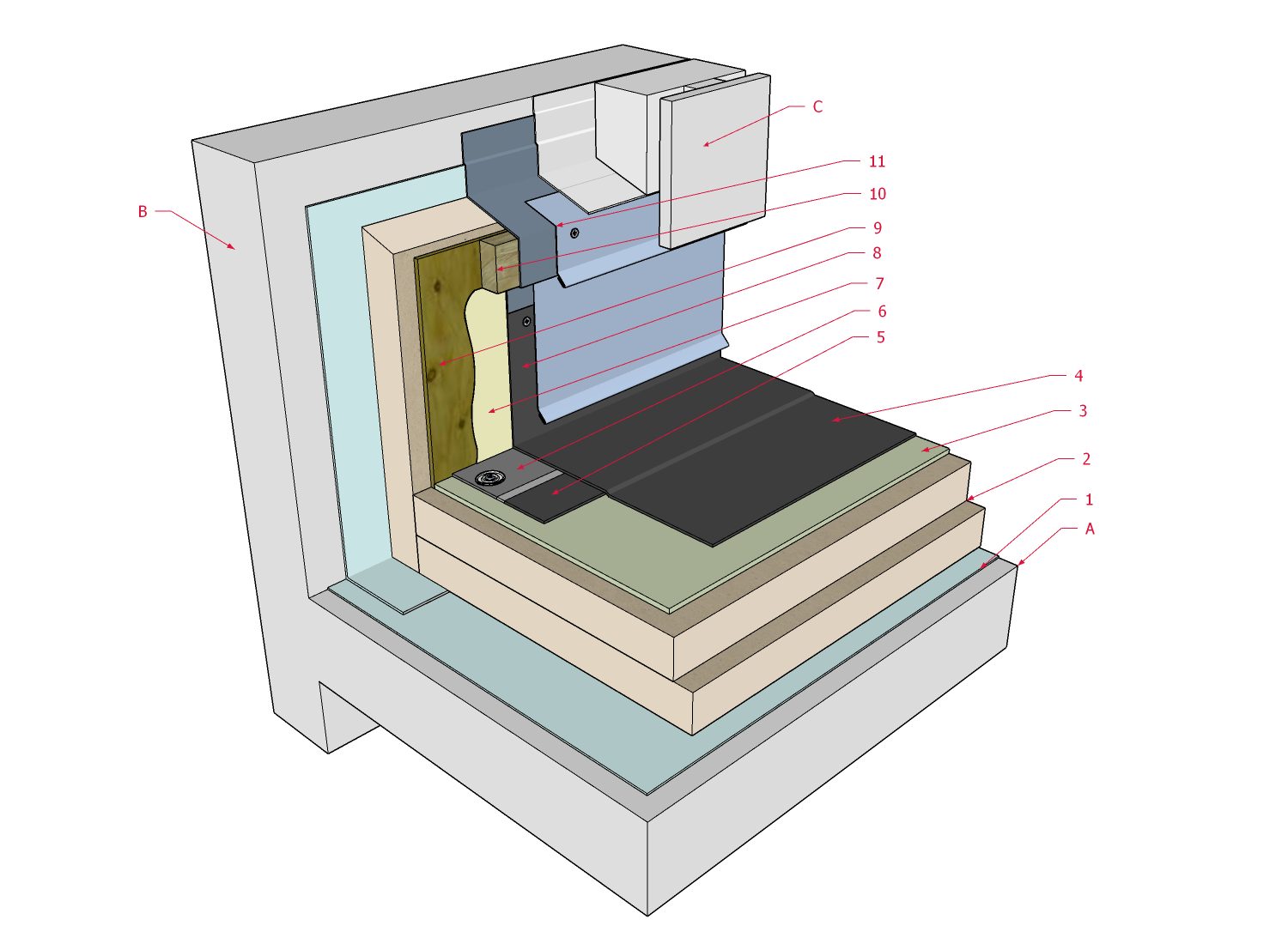
1 WORK INCLUDED
- (1) Suitable field substrate
- May be the roof deck or deck overlay (if an uninsulated system), or insulation and an overlay (if conventionally insulated).
- (2) Primer or adhesive
- For self-adhered or adhered membranes, as required by the manufacturer.
- (3) Base field membrane
- Carried continuously over the outside edge at least 50.8 mm (2”) downward, or 50.8 mm past any cold joint.
- (4) Sealant or mastic
- Applied on membrane, beneath metal edge flashing.
- (5) Metal edge flashing (flush with roof surface):
- Fasteners spaced no more than 203.2 mm (8”) on the top face in two offsetting rows.
- A hemmed drip edge (shown) is required (Refer to Article 13.2.2.1. for fabrication requirements).
- (6) Membrane flashing strip
- Applied to the metal edge flashing and overlapping onto the field membrane at least 101.6 mm (4”). Prime when required by the manufacturer (primer illustrated).
- (7) Cap field membrane
- Installed according to Part 9 requirements.
- (8) Edge mastic
- Apply mastic or another membrane-compatible sealant to the outer exposed edge of the field cap sheet membrane. Coat with granules.
2 RELATED WORK BY OTHERS
- (A) Structural Roof Deck
- Generic and representative only.
- (B) Roof edge substrate
- Wood blocking, required for conventionally insulated roofs.
- (C) Wall assembly
- Generic and representative only.
NOTE: See the SBS Roof Systems Standard for additional requirements.
Back to SBS Roof System Details
© RCABC 2026
RoofStarTM is a registered Trademark of the RCABC.
No reproduction of this material, in whole or in part, is lawful without the expressed permission of the RCABC Guarantee Corp.