
Draft CD 18
Draft CD 18
Division D - Construction Details
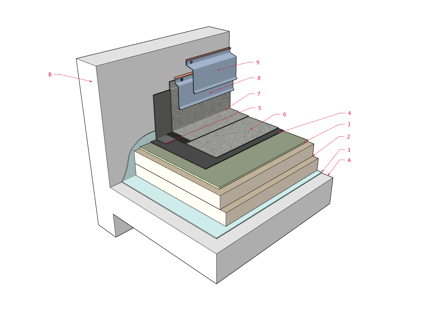
SBS | Membrane Termination F (Wall) ( Article 10.3.2.3.)
| Notice to Reader | |
| Images used in a Construction Detail are representative and not prescriptive, and are not necessarily drawn to scale. They are intended to support the related Standard (Ref. Division A, Article 2.2.1.2.).
The reader may link to the related Article in the detail title, or link to the Standard as it relates to a specific element in the detail. All hyperlinks are displayed blue text. | |
SBS Details
- Drawing NTS
1 WORK INCLUDED
- (1) Air/Vapour Control Layers
- As specified by the Design Authority and installed to provide continuity for optimal control.
- (2) Insulation
- Installed in keeping with Section 7.3. Multiple layering illustrated; layers must be offset and staggered at least 304.8 mm (12”) in each direction.
- (3) Insulation Overlay Panel
- Required for fully adhered membrane systems or when overburden is specified. Panels must be offset and staggered from underlying insulation panels.
- (4) Base Sheet Field Membrane
- See Table 9.2. for permissible application methods and corresponding membrane properties. Membrane must be installed according to the requirements in Section 9.3.
- (5) Base Sheet Flashing Membrane
- Install in keeping with the requirements in Section 10.3. Base sheet membrane flashing must extend onto the roof field at least 101.6 mm (4"). Membrane shall be carried up the vertical substrate at least 203.2 mm (8”) above the finished roof system surface, plus at least 76.2 mm (3”) for wall control layer overlap. In regions where heavy snow accumulation is possible, or to accommodate future roof membrane replacement, membrane should be carried at least 304.8 mm (12”) up the vertical substrate.
- (6) Cap Sheet Field Membrane
- See Table 9.2. for permissible application methods and corresponding membrane properties. Membrane must be installed according to the requirements in Section 9.3.
- (7) Cap Sheet Flashing Membrane
- Install in keeping with the requirements in Section 10.3. Cap sheet membrane flashing must extend onto the field at least 152.4 mm (6"), or at least 50.8 mm (2”) past the edge of the base membrane flashing.
- (8) Primary Surface Reglet Counter-flashing and Sealant
- Surface reglet counter-flashing with tooled sealant shown at top edge of flashing. In this illustration, the linear metal flashing serves to secure the membrane. All membranes applied to a vertical surface must be mechanically fastened.
- (9) Secondary Surface Reglet Counter-flashing and Sealant
- Surface reglet counter-flashing with bead of sealant applied in reglet cut. This flashing provides secondary protection for the primary surface reglet/counter-flashing and safe-guards the sealant from weather-induced deterioration and mechanical damage.
2 RELATED WORK BY OTHERS
- (A) Acceptable Deck
- Illustrated deck is representative. See Sub-section 2.1.5. for acceptable deck types and conditions.
- (B) Wall Structure
- Illustrated wall is representative. Wall control layers (i.e. water resistive barrier) must overlap roofing system to achieve continuity. See Sub-section 2.1.7. for wall conditions.
NOTE: See the SBS Roof Systems Standard for additional requirements.
Back to SBS Roof System Details
© RCABC 2025
RoofStarTM is a registered Trademark of the RCABC.
No reproduction of this material, in whole or in part, is lawful without the expressed permission of the RCABC Guarantee Corp.